EP0185773B1 - Regelpaneel für gleichstrommotor - Google Patents
Regelpaneel für gleichstrommotor Download PDFInfo
- Publication number
- EP0185773B1 EP0185773B1 EP85903051A EP85903051A EP0185773B1 EP 0185773 B1 EP0185773 B1 EP 0185773B1 EP 85903051 A EP85903051 A EP 85903051A EP 85903051 A EP85903051 A EP 85903051A EP 0185773 B1 EP0185773 B1 EP 0185773B1
- Authority
- EP
- European Patent Office
- Prior art keywords
- short bar
- connection terminal
- electrical
- substrate
- control panel
- Prior art date
- Legal status (The legal status is an assumption and is not a legal conclusion. Google has not performed a legal analysis and makes no representation as to the accuracy of the status listed.)
- Expired - Lifetime
Links
- 239000000758 substrate Substances 0.000 claims description 42
- 239000004020 conductor Substances 0.000 abstract description 6
- 239000003990 capacitor Substances 0.000 description 5
- 238000009499 grossing Methods 0.000 description 4
- 230000008929 regeneration Effects 0.000 description 3
- 238000011069 regeneration method Methods 0.000 description 3
- 239000012634 fragment Substances 0.000 description 2
- 230000001172 regenerating effect Effects 0.000 description 2
- 238000010276 construction Methods 0.000 description 1
- 238000010586 diagram Methods 0.000 description 1
- 238000000034 method Methods 0.000 description 1
- 239000012778 molding material Substances 0.000 description 1
- 238000010137 moulding (plastic) Methods 0.000 description 1
Images



Classifications
-
- H—ELECTRICITY
- H05—ELECTRIC TECHNIQUES NOT OTHERWISE PROVIDED FOR
- H05K—PRINTED CIRCUITS; CASINGS OR CONSTRUCTIONAL DETAILS OF ELECTRIC APPARATUS; MANUFACTURE OF ASSEMBLAGES OF ELECTRICAL COMPONENTS
- H05K7/00—Constructional details common to different types of electric apparatus
- H05K7/14—Mounting supporting structure in casing or on frame or rack
- H05K7/1422—Printed circuit boards receptacles, e.g. stacked structures, electronic circuit modules or box like frames
- H05K7/1427—Housings
- H05K7/1432—Housings specially adapted for power drive units or power converters
-
- H—ELECTRICITY
- H01—ELECTRIC ELEMENTS
- H01R—ELECTRICALLY-CONDUCTIVE CONNECTIONS; STRUCTURAL ASSOCIATIONS OF A PLURALITY OF MUTUALLY-INSULATED ELECTRICAL CONNECTING ELEMENTS; COUPLING DEVICES; CURRENT COLLECTORS
- H01R12/00—Structural associations of a plurality of mutually-insulated electrical connecting elements, specially adapted for printed circuits, e.g. printed circuit boards [PCB], flat or ribbon cables, or like generally planar structures, e.g. terminal strips, terminal blocks; Coupling devices specially adapted for printed circuits, flat or ribbon cables, or like generally planar structures; Terminals specially adapted for contact with, or insertion into, printed circuits, flat or ribbon cables, or like generally planar structures
- H01R12/50—Fixed connections
- H01R12/51—Fixed connections for rigid printed circuits or like structures
- H01R12/52—Fixed connections for rigid printed circuits or like structures connecting to other rigid printed circuits or like structures
- H01R12/523—Fixed connections for rigid printed circuits or like structures connecting to other rigid printed circuits or like structures by an interconnection through aligned holes in the boards or multilayer board
-
- H—ELECTRICITY
- H05—ELECTRIC TECHNIQUES NOT OTHERWISE PROVIDED FOR
- H05K—PRINTED CIRCUITS; CASINGS OR CONSTRUCTIONAL DETAILS OF ELECTRIC APPARATUS; MANUFACTURE OF ASSEMBLAGES OF ELECTRICAL COMPONENTS
- H05K7/00—Constructional details common to different types of electric apparatus
- H05K7/14—Mounting supporting structure in casing or on frame or rack
- H05K7/1422—Printed circuit boards receptacles, e.g. stacked structures, electronic circuit modules or box like frames
- H05K7/1427—Housings
- H05K7/1432—Housings specially adapted for power drive units or power converters
- H05K7/14322—Housings specially adapted for power drive units or power converters wherein the control and power circuits of a power converter are arranged within the same casing
-
- H—ELECTRICITY
- H05—ELECTRIC TECHNIQUES NOT OTHERWISE PROVIDED FOR
- H05K—PRINTED CIRCUITS; CASINGS OR CONSTRUCTIONAL DETAILS OF ELECTRIC APPARATUS; MANUFACTURE OF ASSEMBLAGES OF ELECTRICAL COMPONENTS
- H05K7/00—Constructional details common to different types of electric apparatus
- H05K7/14—Mounting supporting structure in casing or on frame or rack
- H05K7/1422—Printed circuit boards receptacles, e.g. stacked structures, electronic circuit modules or box like frames
- H05K7/1427—Housings
- H05K7/1432—Housings specially adapted for power drive units or power converters
- H05K7/14329—Housings specially adapted for power drive units or power converters specially adapted for the configuration of power bus bars
-
- H—ELECTRICITY
- H05—ELECTRIC TECHNIQUES NOT OTHERWISE PROVIDED FOR
- H05K—PRINTED CIRCUITS; CASINGS OR CONSTRUCTIONAL DETAILS OF ELECTRIC APPARATUS; MANUFACTURE OF ASSEMBLAGES OF ELECTRICAL COMPONENTS
- H05K1/00—Printed circuits
- H05K1/02—Details
- H05K1/0213—Electrical arrangements not otherwise provided for
- H05K1/0263—High current adaptations, e.g. printed high current conductors or using auxiliary non-printed means; Fine and coarse circuit patterns on one circuit board
-
- H—ELECTRICITY
- H05—ELECTRIC TECHNIQUES NOT OTHERWISE PROVIDED FOR
- H05K—PRINTED CIRCUITS; CASINGS OR CONSTRUCTIONAL DETAILS OF ELECTRIC APPARATUS; MANUFACTURE OF ASSEMBLAGES OF ELECTRICAL COMPONENTS
- H05K1/00—Printed circuits
- H05K1/18—Printed circuits structurally associated with non-printed electric components
Definitions
- This invention relates to a control panel of an electrical device which may be used in various fields, such as for an AC motor for driving the spindle or table of a machine tool.
- An AC motor is controlled by an inverter.
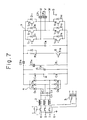
- An inverter control circuit of this type is employed in an arrangement of the kind shown in Fig. 7. Specifically, the inverter control circuit includes an electromagnetic contactor 1, a reactor 2, a diode bridge 4 comprising diodes Dl-D6, a smoothing capacitor 5, a discharge transistor 6 for regeneration, and a transistor inverter 7, these being connected to three-phase inputterminals R, S, T of an AC motor.
- the AC motor (not shown) is connected to output terminals U, V, W of the inverter.
- numeral 3 denotes a control transformer
- Cl-C5 represent surge absorbing capacitors
- R1, R2 designate discharge resistors.
- each electrical component is interrelated and connected by short bars 15 fixedly secured to a short bar substrate 10 of the kind shown in Fig. 9.
- the short bar substrate 10 having the short bars 15 affixed to its lower surface in correlation with the connection terminals 14 of the electrical components is placed on the electrical components, thereby connecting these electrical components in a predetermined relationship.
- Each short bar 15 is formed to include holes 16 at locations corresponding to the connection terminals 14 of the electrical components, each hole having a conductor fitted therein.
- a printed circuit board (not shown) having electronic components mounted thereon is arranged on the short bar substrate 10 and these electronic components are connected to the electrical component assembly, thereby constructing the AC motor control panel.
- the AC motor control panel comprises various electrical components, each of which is arranged in compact form. Accordingly, it is desired that the electrical connections be made automatically and reliably when each component is assembled. Further, when a control panel of this type fails as the result of a faulty electrical component or the like, it is desired that solely this portion of the control panel be capable of quick restoration.
- An object of the present invention isto provide a control panel of the above type, in which electrical components constituting for example the inverter control circuit of an AC motor can be electrically connected in reliable fashion at the time of assembly.
- an electrical control panel having electrical components arranged in a housing and constituting a converter or inverter control circuit of an electrical device; a short bar substrate placed upon a connection terminal led out onto an upper surface of at least one of the electrical components and having a short bar, which contacts the connection terminal, fixedly secured thereto, the substrate being equipped with a hole at a portion corresponding to the connection terminal; a tubular connection member inserted into the hole provided in the short bar substrate for contacting the short bar; and a screw passed through holes provided in the tubular connection member, short bar and connection terminal and screwed into a nut provided on a lower portion of the connection terminal.
- an electrical control panel comprising:
- the present invention enables the electrical connections to be made in a reliable manner by bringing the connection terminals of the electrical components into pressured contact with the short bars owing to the threaded engagement between the screws and nuts.
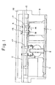
- Fig. 1 is a schematic view showing connections of an AC motor control panel according to the present invention
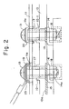
- Fig. 2 is an enlarged view of portion A in Fig. 1
- Fig. 3 is a sectional view showing an embodiment of a connection portion
- Fig. 4(a) is a front view of a tubular connection member
- Fig. 4(b) is a side view of the same
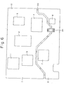
- Figs. 5 and 6 illustrate another embodiment of the present invention, in which Fig. 5 is a plan view of a short bar substrate and Fig. 6 is a view for describing electrical component arrangement positions corresponding to the short bar substrate
- Fig. 7 is a diagram of an inverter circuit of an AC motor
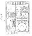
- Fig. 8 is a view showing the arrangement of electrical components constituting the inverter control circuit
- Fig. 9 is a plan view of the short bar substrate.
- Fig. 1 is a schematic view showing connections of a control panel according to the present invention
- Fig. 2 is an enlarged view of a portion A in Fig. 1
- Fig. 3 is a sectional view showing an embodiment of a connection portion
- Fig. 4(a) is a front view of a tubular connection member
- Fig. 4(b) is a side view of the same.
- Numeral 9 denotes a resin-molded housing the interior of which houses such electrical components as the elecgromagnetic contactor 1, reactor 2 and smoothing capacitor 5.
- the terminals 14 of these electrical components are led out onto the upper surface thereof and are arranged to lie on the same plane.
- the short bar substrate 10 for example of the kind shown in Fig.
- connection terminals of these electronic components are connected on the basis of a predetermined relationship.
- a printed circuit board 11 is arranged on the short bar substrate 10 and the printed circuit board 11, short bar substrate 10 and electrical components are electrically connected by tubular connection members 17, screws 13 and nuts 18.
- the short bar substrate 10 is placed in such a manner that bhe short bar 15 will contact the top of the connection terminal 14 led out onto the upper surface of the electrical component.
- the short bar 15 is fitted secured into a recess provided in the lower surface of the short bar substrate 10.
- the lower surface of the short bar protrudes slightly (t 3 ) from below the lower surface of the short bar substrate 10.
- the amount of protrustion t 3 need only be 0.1 to 0.4 mm.
- the short bar substrate 10 and short bar 15 are provided with respective holes 10b, 15a through which is passed the tubular connection member 17 for effecting electrical connection.
- the connection terminal 14 is provided with a corresponding hole 14 through which the screw 13 is passed.
- the short bar substrate 10 consists of a plastic molding material and is integrally molded to include a cylindrical projection 10-1 at the hole 10b to support the tubular connection member 17.
- the tubular connection member 17 With the short bar substrate 10 having been placed on the connection terminal 14 of the electrical component, the tubular connection member 17 is fitted into the hole 10b provided in the short bar substrate 10.
- the tubular connection member 17 comprises a first portion 17-1 of maximum outer diameter, a second portion 17-2 formed by reducing the outer diameter of the first portion 17-1 by t, (0.1 mm), and a third portion 17-3 at the tip, formed by reducing the outer diameter of the second portion 17-2 by t 2 (0.2 mm).
- the short bar substrate 10 is placed so as to situate the corresponding short bar 15 on the lead terminal 14 of the electrical component and the tubular connection member 17 is pressed into the hole 10b of the short bar substrate 10 from thereabove.
- the tubular connection portion 17 When the tubular connection portion 17 is inserted into the hole 10b, which is formed in the cylindrical portion 10-1 of the short bar substrate 10, burrs are scraped from the cylindrical portion 10-1 and burr fragments collect at the end of the tubular connection member 17 and at the location where the connection is made between the tubular connection member 17 and the short bar 15, thus causing poor contact.
- the second portion 17-2 of tubular connection member 17 is formed to have the reduced diameter by cutting its outer periphery down by t, from the first portion 17-1, as set forth above. As a result, a space 22 which receives the burr fragments is formed between the inner circumferential surface of the hole 10b formed in cylindrical portion 10-1 and the second portion 17-2 of the tubular connection member.
- the third portion 17-3 of tubular connection member 17 is formed to have the reduced outer diameter by cutting the second portion 17-2 down by t 2 .
- This third portion 17-3 is fitted into the hole 15a of short bar 15, and a shoulder portion 17a formed at the part of second portion 17-2 where the connection is made contacts the upper surface of the short bar 15.
- the printed circuit board 11 is placed on the short bar substrate 10, as shown in Fig. 2, and the first portion 17-1 of tubular connection member 17 if fitted into a hole 11 a formed in the printed circuit board 11.
- the screw 13 is passed through a connection terminal 23 fixedly secured to the printed circuit board 11 and then through the tubular connection member 17, and the distal end portion of the screw 13 is screwed into the nut 18 provided on the bottom portion of the connection terminal 14 of the electrical component.
- the connection terminal 14 and short bar 15 can be thus be brought into pressured contact to provide a sure electrical connection. It goes without saying that the short bar 15 and connection terminal 23 of printed circuit board 11 are electrically connected by screwing the screw 13 into the nut 18.
- control panel constructed in this manner enables the electrical connections to be reliably effected.
- connections are made with facility since connection can be performed by using a screw tightener.
- Fig. 5 and 6 illustrate another embodiment of the present invention.
- Fig. 5 is a plan view of the short bar substrate
- Fig. 6 is a view for describing electrical component arrangement positions corresponding to the short bar substrate.
- the electromagnetic contactor 1, reactor 2, control transformer 3, diode bridge 4, smoothing capacitor 5, discharge transistor 6 for regeneration, and transistor inverter 7 are arranged at positions corresponding to the short bar substrate 10.
- the regenerative discharge transistor 6 and transistor inverter 7 are unavoidably subjected to electrically severe use and cannot help but have a higher failure rate and shorter life in comparison with the other electrical components.
- the arrangement is such that these electrical components of high failure rate, such as the regenerative discharge transistor 6 and transistor inverter 7, are disposed in a second region II capable of being readily separated from a first region I in which the other components are disposed.
- an electrical connection is contrived between the second region II of the short bar substrate 10 and the first region I via a jumper conductor plate 21, and the first and second regions I, II are connected at several points by plastic-molded members 20. Then, when it is necessary to separate the second region II from the first region I, the jumper conductor plate 21 is removed and the plastic-molded members 20 are cut away.
- the present invention is not limited solely to control panels for AC motors but can also be applied to, e.g., control panels of converters for DC motor drive and control panels of inverters used for other purposes.
Landscapes
- Engineering & Computer Science (AREA)
- Microelectronics & Electronic Packaging (AREA)
- Inverter Devices (AREA)
- Control Of Ac Motors In General (AREA)
- Connections By Means Of Piercing Elements, Nuts, Or Screws (AREA)
Claims (7)
Applications Claiming Priority (2)
| Application Number | Priority Date | Filing Date | Title |
|---|---|---|---|
| JP124749/84 | 1984-06-18 | ||
| JP59124749A JPS614172A (ja) | 1984-06-18 | 1984-06-18 | 交流電動機制御盤 |
Publications (3)
| Publication Number | Publication Date |
|---|---|
| EP0185773A1 EP0185773A1 (de) | 1986-07-02 |
| EP0185773A4 EP0185773A4 (de) | 1987-06-09 |
| EP0185773B1 true EP0185773B1 (de) | 1990-10-31 |
Family
ID=14893158
Family Applications (1)
| Application Number | Title | Priority Date | Filing Date |
|---|---|---|---|
| EP85903051A Expired - Lifetime EP0185773B1 (de) | 1984-06-18 | 1985-06-18 | Regelpaneel für gleichstrommotor |
Country Status (5)
| Country | Link |
|---|---|
| US (1) | US4677540A (de) |
| EP (1) | EP0185773B1 (de) |
| JP (1) | JPS614172A (de) |
| DE (1) | DE3580345D1 (de) |
| WO (1) | WO1986000490A1 (de) |
Families Citing this family (18)
| Publication number | Priority date | Publication date | Assignee | Title |
|---|---|---|---|---|
| GB8624374D0 (en) * | 1986-10-10 | 1986-11-12 | Eaton Gmbh | Terminated electrical component |
| JPH071834B2 (ja) * | 1986-11-12 | 1995-01-11 | フアナツク株式会社 | 制御ユニツト |
| DE3751064T2 (de) * | 1986-12-19 | 1995-06-08 | Fanuc Ltd | Motorantriebseinheit. |
| JPS63271996A (ja) * | 1987-04-28 | 1988-11-09 | Fanuc Ltd | 大電流用プリント基板 |
| JPH0834714B2 (ja) * | 1987-06-16 | 1996-03-29 | ファナック株式会社 | Acスピンドルアンプの筐体構造 |
| DE3802593A1 (de) * | 1988-01-29 | 1989-08-10 | Heidelberger Druckmasch Ag | Umrichter mit gleichspannungs-zwischenkreis |
| GB2239739A (en) * | 1989-11-16 | 1991-07-10 | Motorola Gmbh | Electronic circuit assemblies |
| DE4020026A1 (de) * | 1990-04-30 | 1991-10-31 | Abb Patent Gmbh | Stromrichteranlage mit gleichspannungszwischenkreis und stromrichtermodulen |
| GB9127027D0 (en) * | 1991-12-20 | 1992-02-19 | Int Computers Ltd | Power distribution arrangement |
| JP2007174746A (ja) * | 2005-12-19 | 2007-07-05 | Jtekt Corp | 電気回路基板、基板装置、モータ、モータ装置、電動ポンプ及びモータと電気回路基板又は基板装置とを接続する方法 |
| CN103222053A (zh) * | 2010-09-24 | 2013-07-24 | 半导体元件工业有限责任公司 | 电路装置 |
| JPWO2012039115A1 (ja) * | 2010-09-24 | 2014-02-03 | セミコンダクター・コンポーネンツ・インダストリーズ・リミテッド・ライアビリティ・カンパニー | 回路装置 |
| JP5789264B2 (ja) * | 2010-09-24 | 2015-10-07 | セミコンダクター・コンポーネンツ・インダストリーズ・リミテッド・ライアビリティ・カンパニー | 回路装置 |
| ES2957210T3 (es) * | 2014-12-22 | 2024-01-15 | Mitsubishi Electric Corp | Uso de una placa de circuito |
| FR3043851B1 (fr) * | 2015-11-13 | 2018-01-05 | Valeo Siemens Eautomotive France Sas | Barre de connexion electrique |
| JP2019103205A (ja) * | 2017-11-30 | 2019-06-24 | 日本電産株式会社 | 回路基板、モータ、及びファンモータ |
| CN109089391A (zh) * | 2018-08-06 | 2018-12-25 | 郑州泰恩科技有限公司 | 一种元器件安装高度可调的电气柜 |
| JP7209563B2 (ja) * | 2019-03-19 | 2023-01-20 | 株式会社Subaru | 車載装置 |
Family Cites Families (11)
| Publication number | Priority date | Publication date | Assignee | Title |
|---|---|---|---|---|
| US2613287A (en) * | 1948-10-27 | 1952-10-07 | Ibm | Cross connecting board |
| US2963626A (en) * | 1957-09-10 | 1960-12-06 | Jr Herbert Du Val | Control systems and apparatus |
| US3029367A (en) * | 1959-07-09 | 1962-04-10 | Tomonoh Haruki | Device for assembling the circuits elements |
| US3356902A (en) * | 1966-10-20 | 1967-12-05 | Lear Siegler Inc | Mounting chassis for electrical components |
| JPS5011071B1 (de) * | 1968-06-26 | 1975-04-26 | ||
| GB1294112A (en) * | 1969-04-17 | 1972-10-25 | Lucas Industries Ltd | Full wave rectifier assemblies |
| JPS5529233Y2 (de) * | 1973-10-08 | 1980-07-11 | ||
| FR2293122A1 (fr) * | 1974-11-29 | 1976-06-25 | Alsthom Cgee | Grille support pour boitiers d'appareillage |
| JPS54150986U (de) * | 1978-04-14 | 1979-10-20 | ||
| JPS5617905U (de) * | 1979-07-18 | 1981-02-17 | ||
| US4514784A (en) * | 1983-04-22 | 1985-04-30 | Cray Research, Inc. | Interconnected multiple circuit module |
-
1984
- 1984-06-18 JP JP59124749A patent/JPS614172A/ja active Granted
-
1985
- 1985-06-18 WO PCT/JP1985/000346 patent/WO1986000490A1/ja not_active Ceased
- 1985-06-18 DE DE8585903051T patent/DE3580345D1/de not_active Expired - Lifetime
- 1985-06-18 EP EP85903051A patent/EP0185773B1/de not_active Expired - Lifetime
- 1985-06-18 US US06/834,239 patent/US4677540A/en not_active Expired - Fee Related
Also Published As
| Publication number | Publication date |
|---|---|
| JPH033345B2 (de) | 1991-01-18 |
| WO1986000490A1 (fr) | 1986-01-16 |
| EP0185773A4 (de) | 1987-06-09 |
| US4677540A (en) | 1987-06-30 |
| DE3580345D1 (de) | 1990-12-06 |
| JPS614172A (ja) | 1986-01-10 |
| EP0185773A1 (de) | 1986-07-02 |
Similar Documents
| Publication | Publication Date | Title |
|---|---|---|
| US4677540A (en) | AC motor control panel | |
| US4908738A (en) | Drive motor control unit | |
| US10199804B2 (en) | Busbar locating component | |
| JP3430185B2 (ja) | インバータ装置 | |
| EP0615332B1 (de) | Verbindungsstruktur zum elektrischen Verbinden von Elektromotor und Motorregeleinheit | |
| EP0290617B1 (de) | Regeleinheit | |
| EP0219134B1 (de) | Stromversorgungsanordnung | |
| CA2639182C (en) | Method and apparatus for mounting a circuit board to a transformer | |
| US4737903A (en) | Electronic apparatus | |
| US4794509A (en) | Converter module having cooling elements and a ripple control transmitter apparatus utilizing the same | |
| US6867972B2 (en) | Power component assembly for mechatronic integration of power components | |
| CN219429415U (zh) | 控制柜以及电梯设备 | |
| US10827638B2 (en) | Electric device and motor driving device | |
| CN116331970A (zh) | 控制柜以及电梯设备 | |
| US5278728A (en) | Diode mounting | |
| JPS63157634A (ja) | モ−タ駆動ユニツト | |
| CN113189932B (zh) | 物流伸缩机控制设备 | |
| EP0094823A2 (de) | DC Stromversorgungsgerät | |
| JPH07263098A (ja) | 耐圧試験用短絡コネクタ | |
| JP2506045Y2 (ja) | 制御盤 | |
| JPH11308890A (ja) | サーボコントローラ | |
| JPS63157689A (ja) | モ−タ駆動ユニツト | |
| CN116131632A (zh) | 逆变器 | |
| CN114374342A (zh) | 电机驱动装置 | |
| JPH0794159A (ja) | 電気自動車用バッテリーの配線構造 |
Legal Events
| Date | Code | Title | Description |
|---|---|---|---|
| PUAI | Public reference made under article 153(3) epc to a published international application that has entered the european phase |
Free format text: ORIGINAL CODE: 0009012 |
|
| 17P | Request for examination filed |
Effective date: 19860219 |
|
| AK | Designated contracting states |
Kind code of ref document: A1 Designated state(s): DE FR GB |
|
| A4 | Supplementary search report drawn up and despatched |
Effective date: 19870609 |
|
| 17Q | First examination report despatched |
Effective date: 19891208 |
|
| GRAA | (expected) grant |
Free format text: ORIGINAL CODE: 0009210 |
|
| AK | Designated contracting states |
Kind code of ref document: B1 Designated state(s): DE FR GB |
|
| REF | Corresponds to: |
Ref document number: 3580345 Country of ref document: DE Date of ref document: 19901206 |
|
| ET | Fr: translation filed | ||
| PGFP | Annual fee paid to national office [announced via postgrant information from national office to epo] |
Ref country code: FR Payment date: 19910530 Year of fee payment: 7 |
|
| PGFP | Annual fee paid to national office [announced via postgrant information from national office to epo] |
Ref country code: GB Payment date: 19910607 Year of fee payment: 7 |
|
| PGFP | Annual fee paid to national office [announced via postgrant information from national office to epo] |
Ref country code: DE Payment date: 19910611 Year of fee payment: 7 |
|
| PLBE | No opposition filed within time limit |
Free format text: ORIGINAL CODE: 0009261 |
|
| STAA | Information on the status of an ep patent application or granted ep patent |
Free format text: STATUS: NO OPPOSITION FILED WITHIN TIME LIMIT |
|
| 26N | No opposition filed | ||
| PG25 | Lapsed in a contracting state [announced via postgrant information from national office to epo] |
Ref country code: GB Effective date: 19920618 |
|
| GBPC | Gb: european patent ceased through non-payment of renewal fee |
Effective date: 19920618 |
|
| PG25 | Lapsed in a contracting state [announced via postgrant information from national office to epo] |
Ref country code: FR Effective date: 19930226 |
|
| PG25 | Lapsed in a contracting state [announced via postgrant information from national office to epo] |
Ref country code: DE Effective date: 19930302 |
|
| REG | Reference to a national code |
Ref country code: FR Ref legal event code: ST |