EP0185811B1 - Appareil pour la fabrication d'ensembles d'enveloppes scellées - Google Patents
Appareil pour la fabrication d'ensembles d'enveloppes scellées Download PDFInfo
- Publication number
- EP0185811B1 EP0185811B1 EP84308882A EP84308882A EP0185811B1 EP 0185811 B1 EP0185811 B1 EP 0185811B1 EP 84308882 A EP84308882 A EP 84308882A EP 84308882 A EP84308882 A EP 84308882A EP 0185811 B1 EP0185811 B1 EP 0185811B1
- Authority
- EP
- European Patent Office
- Prior art keywords
- envelope
- intermediate element
- unit
- folding
- transverse
- Prior art date
- Legal status (The legal status is an assumption and is not a legal conclusion. Google has not performed a legal analysis and makes no representation as to the accuracy of the status listed.)
- Expired - Lifetime
Links
- 238000004519 manufacturing process Methods 0.000 title claims description 11
- 230000000712 assembly Effects 0.000 title claims description 8
- 238000000429 assembly Methods 0.000 title claims description 8
- 230000003313 weakening effect Effects 0.000 claims description 20
- 239000012790 adhesive layer Substances 0.000 claims description 19
- 239000010410 layer Substances 0.000 claims description 13
- 238000007789 sealing Methods 0.000 claims description 5
- 230000009172 bursting Effects 0.000 claims 2
- 238000000034 method Methods 0.000 description 5
- 239000000853 adhesive Substances 0.000 description 3
- 238000003780 insertion Methods 0.000 description 3
- 230000037431 insertion Effects 0.000 description 3
- 238000010438 heat treatment Methods 0.000 description 2
- 238000005452 bending Methods 0.000 description 1
- 239000012945 sealing adhesive Substances 0.000 description 1
- 238000004513 sizing Methods 0.000 description 1
- 230000001360 synchronised effect Effects 0.000 description 1
- 239000002562 thickening agent Substances 0.000 description 1
Images


Classifications
-
- B—PERFORMING OPERATIONS; TRANSPORTING
- B31—MAKING ARTICLES OF PAPER, CARDBOARD OR MATERIAL WORKED IN A MANNER ANALOGOUS TO PAPER; WORKING PAPER, CARDBOARD OR MATERIAL WORKED IN A MANNER ANALOGOUS TO PAPER
- B31B—MAKING CONTAINERS OF PAPER, CARDBOARD OR MATERIAL WORKED IN A MANNER ANALOGOUS TO PAPER
- B31B70/00—Making flexible containers, e.g. envelopes or bags
- B31B70/005—Making flexible containers, e.g. envelopes or bags involving a particular layout of the machinery or relative arrangement of its subunits
-
- B—PERFORMING OPERATIONS; TRANSPORTING
- B31—MAKING ARTICLES OF PAPER, CARDBOARD OR MATERIAL WORKED IN A MANNER ANALOGOUS TO PAPER; WORKING PAPER, CARDBOARD OR MATERIAL WORKED IN A MANNER ANALOGOUS TO PAPER
- B31B—MAKING CONTAINERS OF PAPER, CARDBOARD OR MATERIAL WORKED IN A MANNER ANALOGOUS TO PAPER
- B31B2150/00—Flexible containers made from sheets or blanks, e.g. from flattened tubes
-
- B—PERFORMING OPERATIONS; TRANSPORTING
- B31—MAKING ARTICLES OF PAPER, CARDBOARD OR MATERIAL WORKED IN A MANNER ANALOGOUS TO PAPER; WORKING PAPER, CARDBOARD OR MATERIAL WORKED IN A MANNER ANALOGOUS TO PAPER
- B31B—MAKING CONTAINERS OF PAPER, CARDBOARD OR MATERIAL WORKED IN A MANNER ANALOGOUS TO PAPER
- B31B2160/00—Shape of flexible containers
- B31B2160/10—Shape of flexible containers rectangular and flat, i.e. without structural provision for thickness of contents
- B31B2160/106—Shape of flexible containers rectangular and flat, i.e. without structural provision for thickness of contents obtained from sheets cut from larger sheets or webs before finishing the bag forming operations
-
- B—PERFORMING OPERATIONS; TRANSPORTING
- B31—MAKING ARTICLES OF PAPER, CARDBOARD OR MATERIAL WORKED IN A MANNER ANALOGOUS TO PAPER; WORKING PAPER, CARDBOARD OR MATERIAL WORKED IN A MANNER ANALOGOUS TO PAPER
- B31B—MAKING CONTAINERS OF PAPER, CARDBOARD OR MATERIAL WORKED IN A MANNER ANALOGOUS TO PAPER
- B31B2170/00—Construction of flexible containers
- B31B2170/20—Construction of flexible containers having multi-layered walls, e.g. laminated or lined
-
- Y—GENERAL TAGGING OF NEW TECHNOLOGICAL DEVELOPMENTS; GENERAL TAGGING OF CROSS-SECTIONAL TECHNOLOGIES SPANNING OVER SEVERAL SECTIONS OF THE IPC; TECHNICAL SUBJECTS COVERED BY FORMER USPC CROSS-REFERENCE ART COLLECTIONS [XRACs] AND DIGESTS
- Y10—TECHNICAL SUBJECTS COVERED BY FORMER USPC
- Y10T—TECHNICAL SUBJECTS COVERED BY FORMER US CLASSIFICATION
- Y10T225/00—Severing by tearing or breaking
- Y10T225/30—Breaking or tearing apparatus
- Y10T225/35—Work-parting pullers [bursters]
Definitions
- the present invention relates to an apparatus for manufacturing sealed postal mails or the like sealed envelope assemblies.
- the present invention relates to such an apparatus for manufacturing continuous sealed mails and like envelope assemblies, containing intermediate papers that remain free after completing the folding and sealing of envelopes wherein the apparatus processes such envelopes that can be cut off from a continuous sheet along the lateral fold line and folded into three parts at the lateral folding lines and also processes such discrete intermediate elements to be cut off from another continuus sheet or such as . the one previously cut off from the continuous sheet or such as the one to be folded at least along a fold line.
- the apparatus designed for manufacturing either the continuous sealed postal mails or like sealed envelope assemblies selectively combines various intermediate element processors so that any desired type of intermediate elements can be delivered to the main envelope processor.
- the present invention aims at providing such a useful apparatus capable of manufacturing either continuously sealable postal mails or the like envelope assemblies provided with a variety of forms, by allowing the main envelope processor to selectively combine any intermediate element supply unit so that the intermediate elements as the information conveyor can be supplied in a variety of forms.
- apparatus for manufacturing sealed postal or the like envelope assemblies using a discrete envelope unit split from an envelope-forming continuous sheet and an intermediate element having sizes adapted to be enclosed with said envelope unit, said apparatus being characterised by a main envelope processing unit for producing envelopes from said envelope-forming continuous sheet, each of said envelopes having a front layer and a rear layer, said envelope-forming continuous sheet having transverse weakening lines at regular intervals to define an envelope unit section between each adjoining pair of said weakening lines, said envelope unit section having first and second transverse folding lines, defining a first area therebetween for forming said front layer of said envelope, said first area having a length of L1, a second area for forming one portion of said rear layer of said envelope, said second area being connected to said first area at said first transverse folding line, and having a length of L2, a third area for forming the other portion of said rear layer of said envelope, said third area being connected to said first area at said second transverse folding line, and having a length of L3, and said length (L2)
- the sealed mail manufacturing apparatus embodied by the present invention is designed continuously to make up envelope units (E.U) by individually feeding the following into the apparatus; discrete envelopes (2) split from a continuous sheet (1) available for envelopes and discrete intermediate elements (4A, 4B, and 4C) made from intermediate-forming continuous sheets (3A, 3B and 3C) available for intermediate elements shown in the preferred embodiment of Figure 3.
- An example of the envelope forming continuous sheet (1) is shown in Figure 1.
- This sheet (1) is provided with marginal perforation lines (5) and (5) along opposite edges in the direction of its length and also with the marginal perforation split lines (6) and (6) so that the marginal perforation lines (5) and (5) can be cut off along the internal line of these lines (5) and (5).
- the continuous sheet (1) is provided with the tearable transverse weakening lines (7) at regular intervals (LB) in the direction of length, thus defining the area available for the discrete envelope and forming a discrete envelope unit (2) by splitting it from the tearable transverse weakening lines (7).
- the discrete envelope unit (2) defined by the tearable transverse weakening lines (7) is provided with first and second transverse folding lines (8) and (9) allowing it to be sequentially folded in the identical direction.
- the discrete envelope unit (2) is sectioned by the first and second transverse folding lines (8) and (9) to form first area (10) located in the center position and second and third areas (11) and (12) located on opposite sides. As shown in Figure 2, the discrete envelope unit (2) is designed so that the inner rear portion (11) is first folded along the first folding line (8) and then the outer rear portion (12) is folded along the second folding line (9). Length (L1) of the front portion of the envelope corresponds to the length of one side of a complete envelope unit (E.U).
- the envelope sealing adhesive layer (13) is provided on the inner surface of the envelope-forming area of the continuous sheet (1) in the direction of the transverse folding line.
- the adhesive layer (13) comprises two layers; the one (13a) provided along the inner edges of the marginal perforation split lines (6) and (6) and the other layer (13b) provided along the inner part of the transverse edges (12a) of said third rear area (12) of the envelope unit (2), whereas no adhesive layer is provided along the transverse edge portion (11 a) of said second rear area (11) of the envelope unit (2).
- Either thermobonding adhesive agent, pressure-bonding adhesive agent, or water-soluble thickener may be optionally used for the adhesive layer (13).
- Slits (14) are provided along the inner edge of the adhesive layer (13) in such a position corresponding to one-side of a complete envelope unit (E.P).
- a see-through window (15) is provided at an appropriate position of the front area (10) of the envelope unit of the continuous sheet (1).
- a see-through window may be formed by bonding a see-through sheet (17) to the opening (16) on the front area (10) from the inner surface (1a) of the continuous sheet (1) using adhesive agent, or it may be of such a makeup allowing external viewing of a specific part of the written information contained in the envelope.
- Three of the preferred embodiments (3A), (3B) and (3C) in conjunction with the continuous sheets available for the intermediate elements to be inserted into envelopes are shown in Figure 3-A, -B, and -C, respectively.
- Each of these continuous sheets (3A), (3B), and (3C) available for the intermediate sheets is provided with marginal perforation lines (18) and (18) and split lines (19) and (19) for splitting the marginal perforations along the longitudinal edges.
- the intermediate element forming continuous sheet (3A) shown in Figure 3-A makes up the intermediate elements that are longitudinally folded into two parts as shown in Figure 4-A.
- the continuous paper (3A) sections the longitudinally double-folded intermediate element (4A) along the marginal perforation split line (19) and the tearable weakening lines (20A).
- the intermediate element (4A) When the intermediate element (4A) is longitudinally folded into two parts by the longitudinal folding line (21), the intermediate element (4A) fits itself within the length (L1) between the first and second transverse folding lines (8) and (9) of the discrete envelope unit (2), where the intermediate element (4A) has such a size not overlapping the inner length (La) of the adhesive layers (13a) and (13b) provided along the inner edges of the marginal perforation split line (6) of the discrete envelope unit (2).
- the intermediate element forming continuous sheet (3B) shown in Figure 3-B makes up the longitudinally triple-folded intermediate element (4B) shown in Figure 4-B.
- the continuous sheet (3B) having transverse weakening lines (20B), (20B) at regular intervals, the longitudinally folding lines (22) and (23) that fold the intermediate element in the same direction are provided between said weaking lines (20B), (20B).
- the intermediate element forming continuous sheet (3C) shown in Figure 3-C respectively make up transversely triple-folded intermediate elements (4C).
- the intermediate paper forming continuous sheet (3C) also sections the transversely triple-foldable intermediate element (4C) along the marginal perforations (18) and split lines (19) as well as along the tearable weakening lines (20C).
- the transversely triple-foldable intermediate element is provided with transversely folding lines (24) and (25) so that it can be transversely folded into three parts.
- both the transverse and longitudinal length (la) and (lb) of the intermediate elements (4A) and (4B) as well as (4C) are determined according to specific sizes (La) and (L1) optionally preset for the discrete envelope unit (2), whereas the transverse and longitudinal length (la) and (lb) shall be slightly shorter than the length (La) and (L1), respectively.
- Address printing areas (25A), (25B) and (25C) that are available, for example, for automatically printing names of addresses and their addresses using a computerized system, are provided in such a portion which is located on the front surfaces (3a) of the intermediate element forming continuous sheets (3A), (3B), and (3C) and also matches the location of the see-through window (15) on the front surface area (10) of the envelope forming continuous sheet (1).
- the continuous sealed mail manufacturing apparatus (26) embodied by the present invention basically comprises the main envelope processor (27), the intermediate element burst processing unit (28) which can be selectively combined with the main envelope processor (27) for feeding any desired form of the intermediate papers to the main envelope processor (27), the longitudinally triple-folding unit (29), transverse-folding unit (30), and the simple intermediate element inserting unit (31).
- the preferred embodiment also provides such a system in which the longitudinal folder unit (34) composed of the continuous sheet expander bar (32) and a pair of fold-aligning rollers (33) are connected to the front part of the intermediate element burst processing unit (28).
- the main envelope processor (27) is provided with the first feeder unit (35) that delivers the discrete envelope unit (2) to the envelope folding and intermediate element inserting station (F.P) and the second feeder unit (36) that delivers the intermediate element (4) to said envelope folding and intermediate element inserting station (F.P).
- the discrete envelope unit (2) is processed by the burst processor (37) before being delivered to the first feeder unit (35).
- the envelope-forming continuous sheet (1) is held by the continuous sheet holder (38) and then drawn out by the pin tractor unit (39) via an appropriate guide roller (40).
- the continuous sheet (1) After being drawn out by the pin tractor unit (39), the continuous sheet (1) is then split by the splitter (41) at the marginal perforations (5) and (5), which is then burst-processed while passing through a pair of tearing rollers (42) and (43) and finally delivered to the first delivery unit (35).
- a pair of tearing rollers (42) and (43) cause the envelope-forming continuous sheet (1) to be cut off along the tearable transverse weakening lines (7) by means of the differential speed of rotation between both rollers.
- Sensor means (44) available for detecting the pre-determined delivery timing of the discrete envelope units (2) is provided between the first feeder unit (35) and the folding and 'inserting station (F.P), which outputs a detect signal (e1) when detecting the delivery timing of the discrete envelope units (2).
- another sensor (45) is provided, which outputs a detect signal (e2) when detecting the delivery timing of the intermediate papers (4).
- the second feeder unit (36) is designed to operate at a constant speed synchronous with other parts driven by the main motor, and if any difference occurs in the calculated values between the timing detect signals (e1) and (e2), the second feeder unit (36) instantly accelerates or decelerates its operation speed using its own pulse motor (not shown).
- the folder unit provided for the fold- adjustment position (F.P) is described in Figure 12.
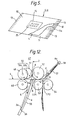
- the folder unit (47) is provided with a pair of feed-rollers (48) and (49) that deliver the intermediate elements (4) to the folding and inserting station wherein the folder unit comprises the drive roller (48) and the other roller (49) which is secured to the first shaft (50a) of the stationary crank shaft (50) through bearings so that it can freely rotate and be pressed against the drive roller (48) along the basic line.
- a roller (51) is secured to the second shaft (50b) of the crank shaft (50) through bearings so that it can rotate freely. This roller (51) makes up a pair with the drive roller (52) so that they are in contact with each other along the basic line.
- the folder unit (47) comprises the first pair of folding rollers composed of the drive roller (52) and the counterpart roller (53) available for folding the discrete envelope unit (2) along the first transverse-folding line (8) and the second pair of folding rollers composed of rollers (53) and (54) for folding the envelope unit (2) along the second transverse-folding line (9).
- the discrete envelope unit (2) is then delivered in the arrowed direction A along the guide (55), while the discrete envelope unit (2) starts to bend itself in the arrowed direction B when its leading edge comes into contact with the stopper (56) which is adjustable to any desired position.
- the stopper (56) presets the position of the discrete envelope unit (2) so that the first traverse-fold line (8) can be positioned at the inlet (T.P1) of the first pair of feeding rollers (52) and (53). Now, the leading edge (4a) of the intermediate element (4) which was synchronously sent out of a pair of rollers (48) and (49) remains being inserted between the discrete envelope units in contact with the first transverse-folding line (8) of the discrete envelope unit (2), and then the leading edge (4a) is inserted between the first pair of folding rollers (52) and (53).
- Both the discrete envelope unit (2) and the discrete intermediate element (4) are then delivered by these folding rollers (52) and (53) in the arrowed direction C along the guide (57), and when the first folded end (Sa) being the edge of the first fold line comes into contact with the position-adjustable stopper (58), the first folded end (Sa) starts to bend in the arrowed direction D.
- the second transverse-folding line (9) of the discrete envelope unit (2) orients its direction towards the inlet (T.P2) of the second pair of rollers (53) and (54) and is then inserted between these rollers (53) and (54).
- the main envelope processor (27) is provided with delivery means (59) that delivers discrete envelopes (E.U) each containing discrete intermediate paper(s) (4) fed by the transverse folding unit (47), heating means (62), for example, such as the one alternately having a roller (60) and a heater panel (61), pressurizing means (63) comprising a plurality of rollers, and a conveyor (64) that delivers the sealed complete envelopes to any desired processors.
- Reference number 65 of Figure 6 indicates the submotor driving rollers of said heating means (62) and pressurizing means (63).
- the intermediate element processors available for the preferred embodiments of the present invention comprises the burst processing unit (28), the identical direction longitudinal triple-folding unit (29), transverse-folder unit (30), and the insertion unit (31), any of which can be selectively combined with the main envelope processor (27).
- the intermediate element processors shown in Figure 6 is suited for processing such intermediate elements shown in Figure 4, where the intermediate element burst processing unit (28) is directly connected to the intermediate element feed-in connection terminal (27A) of the main envelope processor (27).
- the burst processing unit (28) is provided with the longitudinal folder unit (34) in its front part, which comprises the continuous sheet expander bar (32) and a pair of the fold-edge aligning rollers (33). Further, the intermediate paper burst processing unit (28) is provided with the guide rollers (66), pin tractor (67), slitter that splits the marginal perforations, and a pair of rollers (69) and (70) to tear intermediate element (4) along the tearable weakening lines of the continuous sheet (3) that makes up discrete intermediate elements.
- the intermediate element forming continuous sheet (3) is first folded by means of the longitudinal folder (34) provided in the front part of the burst processing unit (28) before being burst-processed and formed into discrete intermediate elements (4A) shown in Figure 4, which are then delivered to the second feeder unit (36) of the main envelope processor (27).
- One of the preferred embodiments shown in Figure 7 is suited for producing such intermediate elements shown in Figure 4-B, wherein it comprises the identical direction longitudinal triple-folding unit (29) provided between the main envelope processor (27) and the burst processing unit (28) which are connected to each other.
- the identical direction longitudinal triple-folding unit (29) comprises a plurality of rollers (71) that form the intermediate paper delivery path, and folding guides (72) and (73) provided on both sides along the paper path, thus making it possible to fold the burst-processed discrete intermediate papers to be folded in the identical direction.
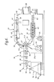
- One of the preferred embodiments shown in Figure 8 uses the transverse-folding unit (30) between the main envelope processor (27) and the intermediate element burst processing unit (28).
- the transverse-folding unit (30) is provided with folding rollers (74) having the similar configuration to that of the folding unit (47) described earlier.
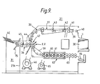
- One of the preferred embodiments shown in Figure 9 uses an insertion unit (31) for inserting a simple intermediate element (4C) into the intermediate paper feed-in connection terminal (27A) of the main envelope processor (27).
- the insertion unit (31) may be of such a configuration to feed a discrete element as an intermediate element or such a configuration provided with the transverse-folding unit (75) to feed a discrete intermediate element folded at least along
- the window provided sealed mail manufacturing apparatus based on the preferred embodiments of the present invention comprising the configurations described above can be realized by using such an envelope-forming continuous sheet reasonably provided with adhesive layers according to a pre-determined specific pattern and such an intermediate paper forming continuous sheet containing characters preliminarily printed by the computerized printers without provision of the adhesive layer at all, thus ideally suited for the computerized printing process, in particular, for the non-impact printing process.
- the bonding is achieved along the center line on the part of rear surface sheet of discrete envelope unit without providing any adhesive layer along the transverse edges of the envelope-forming continuous sheet, any kind of troubles related to the intermediate elements caused by the location of the adhesive layer can be eliminated.
- the lateral bonding part of envelopes can be set at such a position enough to cover the thickness of the intermediate elements, envelopes can be securely sealed independent of the thickness of the intermediate elements.
Landscapes
- Making Paper Articles (AREA)
Claims (6)
Priority Applications (3)
| Application Number | Priority Date | Filing Date | Title |
|---|---|---|---|
| US06/682,277 US4668212A (en) | 1984-12-19 | 1984-12-17 | Process for manufacturing sealed postal envelope assemblies |
| DE8484308882T DE3481763D1 (de) | 1984-12-19 | 1984-12-19 | Apparat fuer die fertigung versiegelter umschlagzusammensetzungen. |
| EP84308882A EP0185811B1 (fr) | 1984-12-19 | 1984-12-19 | Appareil pour la fabrication d'ensembles d'enveloppes scellées |
Applications Claiming Priority (1)
| Application Number | Priority Date | Filing Date | Title |
|---|---|---|---|
| EP84308882A EP0185811B1 (fr) | 1984-12-19 | 1984-12-19 | Appareil pour la fabrication d'ensembles d'enveloppes scellées |
Publications (3)
| Publication Number | Publication Date |
|---|---|
| EP0185811A2 EP0185811A2 (fr) | 1986-07-02 |
| EP0185811A3 EP0185811A3 (en) | 1987-11-25 |
| EP0185811B1 true EP0185811B1 (fr) | 1990-03-28 |
Family
ID=8192839
Family Applications (1)
| Application Number | Title | Priority Date | Filing Date |
|---|---|---|---|
| EP84308882A Expired - Lifetime EP0185811B1 (fr) | 1984-12-19 | 1984-12-19 | Appareil pour la fabrication d'ensembles d'enveloppes scellées |
Country Status (3)
| Country | Link |
|---|---|
| US (1) | US4668212A (fr) |
| EP (1) | EP0185811B1 (fr) |
| DE (1) | DE3481763D1 (fr) |
Families Citing this family (43)
| Publication number | Priority date | Publication date | Assignee | Title |
|---|---|---|---|---|
| USRE34288E (en) * | 1986-01-16 | 1993-06-22 | Pitney Bowes Inc. | Device for folding and sealing sheets |
| US4816108A (en) * | 1986-01-16 | 1989-03-28 | Pitney Bowes Inc. | Device for folding and sealing sheets |
| JPH0422995Y2 (fr) * | 1986-02-28 | 1992-05-27 | ||
| US4784379A (en) * | 1987-03-24 | 1988-11-15 | Bell & Howell Company | Apparatus and method for automated mail |
| US4972655A (en) * | 1987-06-30 | 1990-11-27 | Iseto Shiko Co., Ltd. | Apparatus for manufacturing sealed postal mails or the like envelope assemblies |
| JPH0761760B2 (ja) * | 1987-06-30 | 1995-07-05 | イセト紙工株式会社 | 封入物封閉封筒加工処理装置 |
| US4799989A (en) * | 1987-10-30 | 1989-01-24 | Pitney Bowes Inc. | Document moistening device |
| US4875965A (en) * | 1987-10-30 | 1989-10-24 | Pitney Bowes Inc. | Apparatus for folding and sealing documents |
| EP0372140A1 (fr) * | 1988-12-09 | 1990-06-13 | Iseto Shiko Co. Limited | Appareil pour la fabrication d'envois postaux clos ou d'enveloppes similaires |
| US4900391A (en) * | 1988-12-19 | 1990-02-13 | Xerox Corporation | Recirculating folder for direct mail application |
| EP0375813B1 (fr) * | 1988-12-29 | 1993-06-09 | Iseto Shiko Co. Limited | Appareil pour la fabrication d'envois postaux ou d'enveloppes similaires |
| US6722108B1 (en) | 1989-05-08 | 2004-04-20 | Carol Joyce Witt | Coupon inserting apparatus |
| US5079901A (en) * | 1989-05-08 | 1992-01-14 | Carol J. Witt | Coupon inserting apparatus and method |
| US5054757A (en) * | 1990-03-12 | 1991-10-08 | Martin Samuel W | Mechanism and method for accumulating and folding sheets |
| US5095682A (en) * | 1990-08-06 | 1992-03-17 | Wallace Computer Services, Inc. | Mailer and method and apparatus for making |
| US5108355A (en) * | 1990-09-07 | 1992-04-28 | Graphic Packaging Corporation | Method and apparatus for attaching insert panels to carton blanks |
| US5224919A (en) * | 1990-09-07 | 1993-07-06 | Graphic Packaging Corporation | Method and apparatus for attaching insert panels to carton blanks |
| US5137506A (en) * | 1990-11-05 | 1992-08-11 | The Standard Register Company | In-line folder/gluer |
| JPH07507242A (ja) * | 1992-03-17 | 1995-08-10 | ジー ディー インヴェンション リミテッド | 卓上形封筒製作装置 |
| US5269744A (en) * | 1992-05-21 | 1993-12-14 | Moll Richard J | Two plate buckle folder |
| US5549233A (en) * | 1993-01-29 | 1996-08-27 | C. Joyce Witt | Coupon inserter |
| DK0671326T3 (da) * | 1994-03-08 | 1999-11-08 | Metaverpa Nv | Fremgangsmåde og indretning til omlægning af omhylningselementer omkring trykprodukter |
| FR2724642B1 (fr) * | 1994-09-15 | 1996-12-13 | Danel Ferry | Plieuse pour la fabrication d'enveloppes a deux plis roules avec inserts |
| US5524421A (en) * | 1994-09-27 | 1996-06-11 | Wallace Computer Services, Inc. | One pass system for forming stuffed envelopes |
| FR2725398B1 (fr) * | 1994-10-07 | 1996-11-22 | Danel Ferry | Appareil de scellage a chaud pour documents |
| US5701727A (en) * | 1995-01-13 | 1997-12-30 | Datacard Corporation | Card affixing and form folding system |
| ES2128199B1 (es) * | 1995-03-07 | 1999-12-01 | Martinez Garcia Ramon | Maquina automatica para la formacion de bolsas a partir de laminas troqueladas. |
| US5980439A (en) * | 1996-01-19 | 1999-11-09 | Output Technology Solutions Of California, Inc. | Folding apparatus |
| TR199900961T2 (xx) | 1996-10-31 | 2001-03-21 | Carol Joyce Witt | �� boyutlu birle�tirme yap�s�. |
| US5803261A (en) * | 1996-10-31 | 1998-09-08 | C. Joyce Witt | Three dimensional insert construction |
| US5845462A (en) * | 1996-12-10 | 1998-12-08 | Northfield Corporation | Coupon inserter |
| US6073421A (en) * | 1998-04-09 | 2000-06-13 | Moore U.S.A. Inc. | Apparatus and methods for forming a mailer with contained document from a single web |
| DE19817878A1 (de) * | 1998-04-22 | 1999-11-04 | Juerg Paul Haller | Verfahren zur Herstellung von Drucksendungen, Einrichtung zur Herstellung von Drucksendungen, Umhüllung für eine nach dem Verfahren hergestellte Drucksendung sowie ein zur Verwendung bei einem solchen Verfahren hergestelltes Kuvert |
| FR2782673B1 (fr) * | 1998-09-02 | 2000-11-24 | Neopost Ind | Plieuse/insereuse a chemin d'encarts separe |
| AU772208B2 (en) * | 2000-10-06 | 2004-04-22 | Northfield Corporation | Web Burster/inserter |
| DE10218151A1 (de) * | 2002-04-23 | 2003-11-13 | Bosch Gmbh Robert | Vorrichtung zum Zuführen von Beipackzetteln oder ähnlichem zu Faltschachteln in einer Verpackungsmaschine |
| DE20307170U1 (de) * | 2003-05-08 | 2003-07-03 | Maschinenbau Oppenweiler Binder GmbH & Co. KG, 71570 Oppenweiler | Vorfalzvorrichtung |
| US7549955B2 (en) * | 2004-12-01 | 2009-06-23 | Pitney Bowes Inc. | Method and device for creasing paper |
| US7540125B2 (en) * | 2007-03-26 | 2009-06-02 | Northfield Corporation | Bursting apparatus and method |
| US8793967B2 (en) * | 2008-12-15 | 2014-08-05 | Pitney Bowes Inc. | Methods and apparatus for simultaneous printing on front face and flap of an envelope |
| US20110204132A1 (en) * | 2010-02-19 | 2011-08-25 | Vera Jude C | Tamper-Evident Reusable Mailing Envelope |
| JP5587169B2 (ja) * | 2010-12-28 | 2014-09-10 | 理想科学工業株式会社 | 封入封緘装置及び画像形成システム |
| JP2016078425A (ja) * | 2014-10-15 | 2016-05-16 | ケイディケイ株式会社 | 窓付き封筒の製造方法 |
Citations (2)
| Publication number | Priority date | Publication date | Assignee | Title |
|---|---|---|---|---|
| US3902655A (en) * | 1974-05-13 | 1975-09-02 | Harold W Huffman | Method of producing multi-panel mailing envelope forms in side-by-side interconnected series |
| EP0051099A1 (fr) * | 1980-11-04 | 1982-05-12 | HERVE ET FILS SA (Société anonyme) | Procédé et dispositif de fabrication d'assemblages continus de plis postaux ou autres |
Family Cites Families (11)
| Publication number | Priority date | Publication date | Assignee | Title |
|---|---|---|---|---|
| NL284451A (fr) * | 1961-10-18 | |||
| US3416785A (en) * | 1966-01-24 | 1968-12-17 | Roneo Neopost Ltd | Paper nesting and enveloping apparatus |
| US3628304A (en) * | 1969-12-01 | 1971-12-21 | Smithe Machine Co Inc F L | Method of forming envelopes having inserts therein from a moving blank web |
| DE2112963A1 (de) * | 1971-03-17 | 1972-10-05 | Smithe Machine Co Inc F L | Verfahren zum Herstellen von Briefumschlaegen mit einer darin eingeschlossenen Einlage |
| US4343129A (en) * | 1976-04-27 | 1982-08-10 | G.B.R., Ltd. | Mechanism of making an envelope |
| US4261497A (en) * | 1979-01-18 | 1981-04-14 | Pitney Bowes Inc. | Bursting apparatus |
| US4312169A (en) * | 1980-02-19 | 1982-01-26 | G.B.R., Ltd. | Mechanism for making an envelope around an insert |
| JPS5728756A (en) * | 1980-07-14 | 1982-02-16 | Iseto Shikou Kk | Continuous envelope with window and its manufacturing device |
| US4455809A (en) * | 1980-11-07 | 1984-06-26 | Iseto Shiko Co., Ltd. | Process and apparatus for manufacturing continuous sealed postal or other envelope assemblies |
| US4437852A (en) * | 1981-12-14 | 1984-03-20 | Kurt H. Volk, Inc. | Method of producing mailer with self contained reply envelope |
| DK64187A (da) * | 1986-02-10 | 1987-08-11 | Terumo Corp | Enzym-foeler og fremgangsmaade til fremstilling af en saadan |
-
1984
- 1984-12-17 US US06/682,277 patent/US4668212A/en not_active Expired - Lifetime
- 1984-12-19 DE DE8484308882T patent/DE3481763D1/de not_active Expired - Fee Related
- 1984-12-19 EP EP84308882A patent/EP0185811B1/fr not_active Expired - Lifetime
Patent Citations (2)
| Publication number | Priority date | Publication date | Assignee | Title |
|---|---|---|---|---|
| US3902655A (en) * | 1974-05-13 | 1975-09-02 | Harold W Huffman | Method of producing multi-panel mailing envelope forms in side-by-side interconnected series |
| EP0051099A1 (fr) * | 1980-11-04 | 1982-05-12 | HERVE ET FILS SA (Société anonyme) | Procédé et dispositif de fabrication d'assemblages continus de plis postaux ou autres |
Also Published As
| Publication number | Publication date |
|---|---|
| EP0185811A3 (en) | 1987-11-25 |
| US4668212A (en) | 1987-05-26 |
| EP0185811A2 (fr) | 1986-07-02 |
| DE3481763D1 (de) | 1990-05-03 |
Similar Documents
| Publication | Publication Date | Title |
|---|---|---|
| EP0185811B1 (fr) | Appareil pour la fabrication d'ensembles d'enveloppes scellées | |
| JP2977437B2 (ja) | 郵便用封筒の自動形成方法とその装置 | |
| US5230501A (en) | Apparatus and method for integrating an insert assembly on a printing press | |
| US4733856A (en) | Mechanism for forming personalized envelopes and inserts | |
| CA1241225A (fr) | Methode et dispositif pour la preparation des plis de correspondance-reponse | |
| EP0615490B1 (fr) | Papier continu et appareil destine a former des lettres a partir dudit papier | |
| US5288014A (en) | Two-way mailer | |
| US4340212A (en) | Method and apparatus for producing sheet-like printed products having a folded portion | |
| US5095682A (en) | Mailer and method and apparatus for making | |
| US6865864B2 (en) | Inline formed crossfold package and method | |
| US5064115A (en) | Mailer and method and apparatus for making | |
| US5524421A (en) | One pass system for forming stuffed envelopes | |
| CA1311641C (fr) | Appareil de confection d'envois postaux cachetes ou d'enveloppes assimilables | |
| EP0528576A1 (fr) | Article de correspondance et ensembles de formulaires commerciaux pour obtenir ces articles | |
| US6042672A (en) | Sealed paper making method | |
| US7878494B1 (en) | Making magazine pop-up formats | |
| US20080067800A1 (en) | Stand-up advertising insert | |
| JPS6251563A (ja) | 第2折り部及び第3折り部を有する紙折り装置 | |
| JP2009061696A (ja) | アルバム製本方法及びアルバム製本装置 | |
| JP3577344B2 (ja) | 用紙折り畳み装置 | |
| JPS6013534A (ja) | 窓付き連続封筒の加工処理装置 | |
| JPS59187894A (ja) | 綴込小冊子の製造方法 | |
| JPS6210179B2 (fr) | ||
| JPH1086561A (ja) | 封書の作成方法 | |
| JP2521140B2 (ja) | 封入物封閉封筒加工処理装置 |
Legal Events
| Date | Code | Title | Description |
|---|---|---|---|
| PUAI | Public reference made under article 153(3) epc to a published international application that has entered the european phase |
Free format text: ORIGINAL CODE: 0009012 |
|
| AK | Designated contracting states |
Kind code of ref document: A2 Designated state(s): DE FR GB |
|
| PUAL | Search report despatched |
Free format text: ORIGINAL CODE: 0009013 |
|
| AK | Designated contracting states |
Kind code of ref document: A3 Designated state(s): DE FR GB |
|
| 17P | Request for examination filed |
Effective date: 19880511 |
|
| 17Q | First examination report despatched |
Effective date: 19880929 |
|
| GRAA | (expected) grant |
Free format text: ORIGINAL CODE: 0009210 |
|
| AK | Designated contracting states |
Kind code of ref document: B1 Designated state(s): DE FR GB |
|
| REF | Corresponds to: |
Ref document number: 3481763 Country of ref document: DE Date of ref document: 19900503 |
|
| ET | Fr: translation filed | ||
| PLBE | No opposition filed within time limit |
Free format text: ORIGINAL CODE: 0009261 |
|
| STAA | Information on the status of an ep patent application or granted ep patent |
Free format text: STATUS: NO OPPOSITION FILED WITHIN TIME LIMIT |
|
| 26N | No opposition filed | ||
| PGFP | Annual fee paid to national office [announced via postgrant information from national office to epo] |
Ref country code: GB Payment date: 20001115 Year of fee payment: 17 |
|
| PGFP | Annual fee paid to national office [announced via postgrant information from national office to epo] |
Ref country code: DE Payment date: 20001213 Year of fee payment: 17 |
|
| PGFP | Annual fee paid to national office [announced via postgrant information from national office to epo] |
Ref country code: FR Payment date: 20001219 Year of fee payment: 17 |
|
| PG25 | Lapsed in a contracting state [announced via postgrant information from national office to epo] |
Ref country code: GB Free format text: LAPSE BECAUSE OF NON-PAYMENT OF DUE FEES Effective date: 20011219 |
|
| REG | Reference to a national code |
Ref country code: GB Ref legal event code: IF02 |
|
| PG25 | Lapsed in a contracting state [announced via postgrant information from national office to epo] |
Ref country code: DE Free format text: LAPSE BECAUSE OF NON-PAYMENT OF DUE FEES Effective date: 20020702 |
|
| GBPC | Gb: european patent ceased through non-payment of renewal fee |
Effective date: 20011219 |
|
| PG25 | Lapsed in a contracting state [announced via postgrant information from national office to epo] |
Ref country code: FR Free format text: LAPSE BECAUSE OF NON-PAYMENT OF DUE FEES Effective date: 20020830 |
|
| REG | Reference to a national code |
Ref country code: FR Ref legal event code: ST |