EP0185868B1 - Verfahren und Vorrichtung zur Durchführung von heterogenen, stofftransportlimitierenden Reaktionen - Google Patents
Verfahren und Vorrichtung zur Durchführung von heterogenen, stofftransportlimitierenden Reaktionen Download PDFInfo
- Publication number
- EP0185868B1 EP0185868B1 EP85112963A EP85112963A EP0185868B1 EP 0185868 B1 EP0185868 B1 EP 0185868B1 EP 85112963 A EP85112963 A EP 85112963A EP 85112963 A EP85112963 A EP 85112963A EP 0185868 B1 EP0185868 B1 EP 0185868B1
- Authority
- EP
- European Patent Office
- Prior art keywords
- reactor
- internal tube
- liquid
- reaction
- reactants
- Prior art date
- Legal status (The legal status is an assumption and is not a legal conclusion. Google has not performed a legal analysis and makes no representation as to the accuracy of the status listed.)
- Expired - Lifetime
Links
- 238000006243 chemical reaction Methods 0.000 title claims abstract description 35
- 238000000034 method Methods 0.000 title claims abstract description 14
- 239000007788 liquid Substances 0.000 claims abstract description 28
- 239000000376 reactant Substances 0.000 claims abstract description 25
- 239000006185 dispersion Substances 0.000 claims abstract description 12
- 230000021715 photosynthesis, light harvesting Effects 0.000 claims abstract description 10
- 230000003068 static effect Effects 0.000 claims abstract description 9
- 239000007795 chemical reaction product Substances 0.000 claims abstract description 6
- 239000000047 product Substances 0.000 claims abstract description 6
- 239000003054 catalyst Substances 0.000 claims abstract description 4
- 230000001939 inductive effect Effects 0.000 claims abstract 2
- 239000000463 material Substances 0.000 claims abstract 2
- VGGSQFUCUMXWEO-UHFFFAOYSA-N Ethene Chemical compound C=C VGGSQFUCUMXWEO-UHFFFAOYSA-N 0.000 claims description 11
- 239000005977 Ethylene Substances 0.000 claims description 11
- ZAMOUSCENKQFHK-UHFFFAOYSA-N Chlorine atom Chemical compound [Cl] ZAMOUSCENKQFHK-UHFFFAOYSA-N 0.000 claims description 10
- 239000000460 chlorine Substances 0.000 claims description 10
- 229910052801 chlorine Inorganic materials 0.000 claims description 10
- 239000007789 gas Substances 0.000 description 11
- WSLDOOZREJYCGB-UHFFFAOYSA-N 1,2-Dichloroethane Chemical compound ClCCCl WSLDOOZREJYCGB-UHFFFAOYSA-N 0.000 description 10
- 239000012071 phase Substances 0.000 description 7
- YXFVVABEGXRONW-UHFFFAOYSA-N Toluene Chemical compound CC1=CC=CC=C1 YXFVVABEGXRONW-UHFFFAOYSA-N 0.000 description 3
- 238000005660 chlorination reaction Methods 0.000 description 3
- 239000007791 liquid phase Substances 0.000 description 3
- IKHGUXGNUITLKF-UHFFFAOYSA-N Acetaldehyde Chemical compound CC=O IKHGUXGNUITLKF-UHFFFAOYSA-N 0.000 description 2
- IJGRMHOSHXDMSA-UHFFFAOYSA-N Atomic nitrogen Chemical compound N#N IJGRMHOSHXDMSA-UHFFFAOYSA-N 0.000 description 2
- CURLTUGMZLYLDI-UHFFFAOYSA-N Carbon dioxide Chemical compound O=C=O CURLTUGMZLYLDI-UHFFFAOYSA-N 0.000 description 2
- URLKBWYHVLBVBO-UHFFFAOYSA-N Para-Xylene Chemical group CC1=CC=C(C)C=C1 URLKBWYHVLBVBO-UHFFFAOYSA-N 0.000 description 2
- KKEYFWRCBNTPAC-UHFFFAOYSA-N Terephthalic acid Chemical compound OC(=O)C1=CC=C(C(O)=O)C=C1 KKEYFWRCBNTPAC-UHFFFAOYSA-N 0.000 description 2
- 239000012295 chemical reaction liquid Substances 0.000 description 2
- 208000012839 conversion disease Diseases 0.000 description 2
- 239000007792 gaseous phase Substances 0.000 description 2
- NNPPMTNAJDCUHE-UHFFFAOYSA-N isobutane Chemical compound CC(C)C NNPPMTNAJDCUHE-UHFFFAOYSA-N 0.000 description 2
- 238000007254 oxidation reaction Methods 0.000 description 2
- CIHOLLKRGTVIJN-UHFFFAOYSA-N tert‐butyl hydroperoxide Chemical compound CC(C)(C)OO CIHOLLKRGTVIJN-UHFFFAOYSA-N 0.000 description 2
- UFHFLCQGNIYNRP-UHFFFAOYSA-N Hydrogen Chemical compound [H][H] UFHFLCQGNIYNRP-UHFFFAOYSA-N 0.000 description 1
- 238000006887 Ullmann reaction Methods 0.000 description 1
- 239000001569 carbon dioxide Substances 0.000 description 1
- 229910002092 carbon dioxide Inorganic materials 0.000 description 1
- 230000006315 carbonylation Effects 0.000 description 1
- 238000005810 carbonylation reaction Methods 0.000 description 1
- 238000006757 chemical reactions by type Methods 0.000 description 1
- 238000004581 coalescence Methods 0.000 description 1
- 239000001257 hydrogen Substances 0.000 description 1
- 229910052739 hydrogen Inorganic materials 0.000 description 1
- 238000005984 hydrogenation reaction Methods 0.000 description 1
- 230000006698 induction Effects 0.000 description 1
- 239000012263 liquid product Substances 0.000 description 1
- 229910052757 nitrogen Inorganic materials 0.000 description 1
- 230000003647 oxidation Effects 0.000 description 1
- 230000002093 peripheral effect Effects 0.000 description 1
- 238000005191 phase separation Methods 0.000 description 1
- 230000001681 protective effect Effects 0.000 description 1
- 239000000126 substance Substances 0.000 description 1
- 230000007306 turnover Effects 0.000 description 1
Images

Classifications
-
- B—PERFORMING OPERATIONS; TRANSPORTING
- B01—PHYSICAL OR CHEMICAL PROCESSES OR APPARATUS IN GENERAL
- B01J—CHEMICAL OR PHYSICAL PROCESSES, e.g. CATALYSIS OR COLLOID CHEMISTRY; THEIR RELEVANT APPARATUS
- B01J10/00—Chemical processes in general for reacting liquid with gaseous media other than in the presence of solid particles, or apparatus specially adapted therefor
-
- B—PERFORMING OPERATIONS; TRANSPORTING
- B01—PHYSICAL OR CHEMICAL PROCESSES OR APPARATUS IN GENERAL
- B01J—CHEMICAL OR PHYSICAL PROCESSES, e.g. CATALYSIS OR COLLOID CHEMISTRY; THEIR RELEVANT APPARATUS
- B01J19/00—Chemical, physical or physico-chemical processes in general; Their relevant apparatus
- B01J19/24—Stationary reactors without moving elements inside
- B01J19/2415—Tubular reactors
- B01J19/2435—Loop-type reactors
-
- C—CHEMISTRY; METALLURGY
- C07—ORGANIC CHEMISTRY
- C07C—ACYCLIC OR CARBOCYCLIC COMPOUNDS
- C07C17/00—Preparation of halogenated hydrocarbons
- C07C17/013—Preparation of halogenated hydrocarbons by addition of halogens
- C07C17/02—Preparation of halogenated hydrocarbons by addition of halogens to unsaturated hydrocarbons
Definitions
- the invention relates to a method and a device for carrying out heterogeneous, substance transport-limiting reactions according to the preamble of patent claim 1.
- reaction turnover i.e. the conversion of the reactants to the desired product
- selectivity of a reaction can be improved by measures to improve the mass and heat transport.
- the reactants and in particular ethylene are present in the most uniform, finely divided gas / liquid dispersion possible.
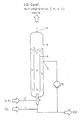
- a cylindrical reaction vessel 6 a feed line for the reactants, e.g. a feed line 1 with chlorine and a feed line 2 with gaseous ethylene, which are mixed in a distributor 9 and introduced into the reactor from below, an inner tube 4, an outlet 5 for the reaction product and those dissolved or dispersed in the reaction product Components, a pump 10 for the transport of the liquid phase emerging from the reactor and an outlet 11 for the gaseous components.
- a feed line for the reactants e.g. a feed line 1 with chlorine and a feed line 2 with gaseous ethylene, which are mixed in a distributor 9 and introduced into the reactor from below
- an inner tube 4 an outlet 5 for the reaction product and those dissolved or dispersed in the reaction product Components
- a pump 10 for the transport of the liquid phase emerging from the reactor and an outlet 11 for the gaseous components.
- the aspect of a homogeneous distribution with a sufficiently large energy dissipation density in the liquid phase is particularly important in the case of gas / liquid dispersions which tend to coalesce, such as, for example, the ethylene / EDC dispersion.
- gas / liquid dispersions which tend to coalesce, such as, for example, the ethylene / EDC dispersion.
- the requirement is only partially met by the processes according to the protective rights mentioned, so that unreacted gaseous reactants occur in the gas space at the top of the reactor when stoichiometric addition is carried out.
- the invention has for its object to develop a method and a device in which the previously described disadvantages of an inhomogeneous energy dissipation density during the reaction and the undesired emergence of the reactants from the reaction phase do not occur and thus a higher space-time yield in the device is made possible.
- the liquid with the gaseous phase is dispersed in a static mixer and then introduced into a reactor.
- the method according to the invention it is achieved that the dispersion and induction of the reaction with an energy dissipation density of more than 10 kW / m 3 up to a.
- the gas / liquid dispersion obtained is introduced from above into an inner tube of the reactor which is completely filled with liquid reaction product in such a way that, by means of pulse exchange, the reactor contents carry out a circulation movement centrally downwards and in the peripheral zones via a deflection upwards.
- the almost completely reacted reactants leave the reactor at the lowest point as an almost bubble-free reaction liquid.
- the geometric relationships between the inner tube and the reactor diameter are selected such that the liquid flow in the inner tube flows down at a speed which is equal to or greater than the rate of rise of the corresponding medium-sized gas bubbles when leaving the static mixer, to avoid bubble coalescence and thus phase separation in the reactor.
- the speed of the liquid flow — in this case directed upward — is greater than that The rate of rise of the gas bubbles contained in this stream is of medium size.
- the gas / liquid dispersion flows through a conical nozzle after leaving the mixer.
- the ratio of the diameter Di of the inner tube to the diameter Dü of the nozzle outlet of this nozzle is in the range from 10 “Di / Dü) 2 ⁇ 80.
- the ratio of the length Li of the inner tube to the diameter Di of the inner tube is in the range 10-Li / Di-30, the ratio of the diameter Di of the inner tube to the diameter D of the reactor is in the range 0.4 ⁇ Di / D ⁇ 0.9 .
- the energy dissipation density outside the static mixer in the operating state in the reactor is preferably at least 0.05 kW / m3 .
- the process according to the invention is used according to claim 4, preferably with chlorine as the reactant contained in the reaction phase and ethylene as the gaseous reactant.
- it can also be used advantageously for other reactions, e.g. Oxidation reactions in the liquid phase (for example oxidation of i-butane to tert-butyl hydroperoxide, p-xylene to terephthalic acid, ethylene to acetaldehyde), chlorinations (for example of toluene), carbonylations and hydrogenations.
- the reactor is cylindrical. However, it can also have another shape, e.g. be conical.
- the device according to the invention is shown schematically in FIG.
- it consists of a cylindrical reaction vessel 6, in which the reaction is equal to the filling volume, a top-to-bottom feed line for the reactants, such as a feed line 1 with chlorine dissolved in EDC and a feed line 2 with gaseous ethylene , a static mixer 3 in which the liquid with the gaseous phase is dispersed, the reaction is induced and the reaction takes place for the most part using a high and uniform energy dissipation density> 10 kW / m 3 .
- the remaining reactive gas / liquid dispersion is advantageously passed via a conical nozzle 8 into an inner tube 4, which is arranged centrally and is completely filled with reaction liquid, such as EDC.
- the ratio of the diameter Di of the inner tube to the diameter D of the reactor is chosen so that the flow rate in the inner tube is at least equal to, preferably greater than the rate of rise of the gas bubbles when entering the inner tube 4.
- the mean residence time is inevitably obtained for all gas bubbles the length of time in the inner tube and in the annular space outside the inner tube and is determined by the length of the inner tube and the corresponding circulation speeds inside and outside the inner tube by the choice of suitable diameter ratios 0.4 ⁇ Di / D ⁇ 0.9.
- reaction product and the amount of circulation introduced with the chlorine, as well as unreacted proportions of reactants and inert components of the reactants, e.g. Nitrogen, hydrogen and carbon dioxide are passed out of the reactor at outlet 5.
- a chlorine-containing EDC solution consisting of 20 m 3 / h EDC, in which 400 kg / h chlorine are dissolved, is fed via line 1 with 153 kg / h ethylene via line 2 into the static mixer 3.
- the reaction conversion of the exothermic reaction heats the chlorine-containing EDC solution from 99 ° C to 122 ° C when leaving this reaction zone.
- a product temperature of 132 ° C. with an ethylene conversion of about 98% is measured at the outlet 5 of the reactor.
Landscapes
- Chemical & Material Sciences (AREA)
- Organic Chemistry (AREA)
- Chemical Kinetics & Catalysis (AREA)
- Organic Low-Molecular-Weight Compounds And Preparation Thereof (AREA)
- Physical Or Chemical Processes And Apparatus (AREA)
- Treatment Of Fiber Materials (AREA)
Description
- Die Erfindung betrifft ein Verfahren und eine Vorrichtung zur Durchführung von heterogenen, stofftransportlimitierenden Reaktionen gemäß dem Oberbegriff des Patentanspruchs 1.
- Die Direktchlorierung von Ethylen und Chlor zu 1.2-Dichlorethan (EDC) in einem flüssigen, katalysatorhaltigen Produktstrom aus EDC kann beispeilhaft für den Reaktionstyp einer heterogenen, exothermen und stofftransportlimierenden Reaktion angesehen werden (Ullmanns Enzyklopädie der technischen Chemie, 4. Aufl., Bd. 9 [1975], Seite 426-427).
- Der Reaktionsumsatz, d.h. der Umsatz der Reaktanden zu dem gewünschten Produkt, und die Selektivität einer Reaktion können durch Maßnahmen zur Verbesserung des Stoff- und Wärmetransports verbessert werden. So werden z.B. auch bei den bekannten Vorrichtungen zur Durchführung der Direktchlorierung zu EDC Reaktionsbedingungen angestrebt, bei denen die Reaktanden und hierbei insbesondere Ethylen in möglichst einheitlicher, feinverteilter Gas/Flüssig-Dispersion vorliegen.
- Ein wesentliches gemeinsames Merkmal der für diesen Reaktionstyp bekannten Vorrichtungen ist darin zu sehen, daß die im Produktstrom mehr oder weniger teilweise gelösten Reaktanden Chlor und Ethylen grundsätzlich von unten in den Reaktor eingeleitet werden, mit der in Zirkulation gebrachten flüssigen Reaktionsphase in einem Innenrohr zentral nach oben transportiert werden, dabei an die Phasengrenze zwischen flüssigem Produkt und Dampfraum am Kopf des Reaktors gelangen und teilweise aus der katalysatorhaltigen, flüssigen Reaktionsphase entweichen oder auch zum Teil mit der abwärts führenden Flüssigkeitsbewegung außerhalb des Innenrohres wieder nach unten transportiert werden. Bei dieser Verfahrensweise kann das unerwünschte und den Reaktionsumsatz beeinflussende Heraustreten der gasförmigen Reaktanden aus der flüssigen Reaktionsphase in den Dampfraum des Reaktors nicht vollständig vermieden werden. In Fig. 1 ist schematisch eine bekannte Vorrichtung dargestellt. Sie besteht in der gezeigten Ausführung aus einem zylindrischen Reaktionsgefäß 6, einer Zuleitung der Reaktanden, wie z.B. einer Zuleitung 1 mit Chlor und einer Zuleitung 2 mit gasförmigem Ethylen, welche in einem Verteiler 9 gemischt und über diesen von unten in den Reaktor eingeleitet werden, einem Innenrohr 4, einem Austritt 5 für das Reaktionsprodukt und die im Reaktionsprodukt gelösten bzw. mit diesem dispergierten Bestandteile, einer Pumpe 10 für den Transport der aus dem Reaktor austretenden flüssigen Phase und einem Austritt 11 für die gasförmigen Bestandteile.
- Unter konstanten Reaktionsbedingungen, wie z.B. Konzentrationen (Gasanteil), Temperatur usw., wird dieser Entzug der gasförmigen Reaktanden aus der flüssigen Reaktionsphase maßgebend von der Blasengröße und -verteilung im Innenrohr, der Aufwärtsgeschwindigkeit der GasFlüssig-Dispersion im Innenrohr und der Flüssigkeitsstandhöhe bestimmt. Die zur Erzeugung einer hohen volumenspezifischen Stoffaustauschfläche erforderliche Energiedissipationsdichte kann wie in der EP-OS 0075 742 und der DE-PS 33 40 624 (Stand der Technik im Sinne von Art. 54.(3) EPU) beschrieben erreicht werden (zum Begriff der Energiedissipationsdichte siehe Ullmanns Enzyklopädie der technischen Chemie, 4 Aufl., Bd. 3 1973, S. 358-360). In diesem Zusammenhang ist insbesondere bei Gas/Flüssig-Dispersionen, die zur Koaleszenzneigen, wie beispeilsweise die Ethylen/EDC-Dispersion, der Aspekt einer homogenen Verteilung bei hinreichend größer Energiedissipationsdichte in der flüssigen Phase von Bedeutung. Die Forderung wird von den Verfahren gemäß den genannten Schutzrechten nur zum Teil erfüllt, so daß bei stöchiometrischer Zugabe nicht umgesetzte gasförmige Reaktanden im Gasraum am Kopf des Reaktors anfallen.
- Der Erfindung liegt die Aufgabe zugrunde, ein Verfahren und eine Vorrichtung zu entwickeln, bei der die vorher beschriebenen Nachteile einer inhomogenen Energiedissipationsdichte während der Reaktion und das unerwünschte Austreten der Reaktanden aus der Reaktionsphase nicht auftreten und damit eine höhere Raumzeitausbeute in der Vorrichtung, ermöglicht wird.
- Diese Aufgabe wird gemäß den kennzeichnenden Merkmalen des Patentanspruchs 1 gelöst. In den Unteransprüchen sind vorteilhafte Ausgestaltungen der Erfindung dargestellt.
- Gemäß der Erfindung wird die flüssige mit der gasförmigen Phase in einem statischen Mischer dispergiert und anschließend in einen Reaktor eingeleitet. Mit dem erfindungsgemäßen Verfahren wird erericht, daß die Dispergierung und Induzierung der Reaktion mit einer Energiedissipationsdichte von mehr als 10 kW/m3 bis zu einem.
- Umsatz von mindestens 60% erfolgt. Die erhaltene Gas/Flüssig-Dispersion wird derart von oben in ein Innenrohr des vollständig mit flüssigem Reaktionsprodukt gefüllten Reaktors eingeleitet, daß durch Impulsaustausch der Reaktorinhalt eine Zirkulationsbewegung zentral nach unten und in den Randzonen über eine Umlenkung nach oben ausführt. Die nahezu vollständig umgesetzten Reaktanden verlassen den Reaktor an der tiefsten Stelle als nahezu blasenfreie Reaktionsflüssigkeit. Bei der erfindungsgemäßen Vorrichtung werden die geometrischen Verhältnisse zwischen dem Innenrohr- und dem Reaktordurchmeser so gewählt, daß der Flüssigkeitsstrom im Innenrohr mit einer Geschwindigkeit nach unten strömt, die gleich der oder größer ist als die Steiggeschwindigkeit der entsprechenden Gasblasen mittlerer Größe beim Verlassen des statischen Mischers, um eine Blasenkoaleszenz und damit eine Phasentrennung im Reaktor zu vermeiden. Für die Strömung außerhalb des Innenrohres gilt ebenfalls die Bedingung, daß die Geschwindigkeit des-in diesem Fall nach oben gerichteten-Flüssigkeitsstroms größer als die Steiggeschwindigkeit der in diesem Strom enthaltenen Gasblasen mittlerer Größe ist.
- Dies wird besonders einfach durch die vorzugsweise Ausgestaltung der Erfindung gemäß den Ansprüchen 2, 5 und 6 erreicht. Die Gas/Flüssig-Dispersion durchströmt nach dem Verlassen des Mischers eine konische Düse. Das Verhältnis des Durchmessers Di des Innenrohres zum Durchmesser Dü des Düsenaustritts dieser Düse liegt im Bereich von 10«Di/Dü)2<80. Das Verhältnis der Länge Li des Innenrohres zum Durchmesser Di des Innenrohres liegt im Bereich 10--Li/Di--30, das Verhältnis des Durchmessers Di des Innenrohres zum Durchmesser D des Reaktors im Bereich 0,4<Di/D<0,9.
- Statt der konischen Düse kann auch ein anderer Hohlkörper mit verengtem Querschnitt bei der erfindungsgemäßen Vorrichtung verwendet werden.
- Vorzugsweise beträgt beim erfindungsgemäßen Verfahren gemäß Anspruch 3, außerhalb des statischen Mischers im Betriebszustand im Reaktor die Energiedissipationsdichte mindestens 0,05 kW/m3.
- Das erfindungsgemäße Verfahren wird nach Anspruch 4, vorzugsweise mit Chlor als in der Reaktionsphase enthaltenem Reaktanden und Ethylen als gasförmigem Reaktanden eingesetzt. Es kann jedoch vorteilhaft auch für andere Reaktionen verwendet werden, wie z.B. Oxidationsreaktionen in der Flüssigphase (beispielsweise Oxidation von i-Butan zu tert. Butylhydroperoxid, p-Xylol zu Terephthalsäure, Ethylen zu Acetaldehyd), Chlorierungen (beispielsweise von Toluol), Carbonylierungen und Hydrierungen.
- In vorteilhafter Ausgestaltung nach Anspruch 7 ist der Reaktor zylindrisch. Er kann jedoch auch eine andere Form aufweisen, z.B. konisch ausgebildet sein.
- Die Erfindung wird nachfolgend anhand der Zeichnung und eines Beispiels näher erläutert.
- In Fig. 2 ist schematisch die erfindungsgemäß Vorrichtung dargestellt. Sie besteht, in der gezeigten Ausführung aus einem zylindrischen Reaktionsgefäß 6, in welchem das Reaktions- gleich dem Füllvolumen ist, einer von oben nach unten gerichteten Zuleitung der Reaktanden, wie z.B. einer Zuleitung 1 mit in EDC gelöstem Chlor und einer Zuleitung 2 mit gasförmigem Ethylen, einem statischen Mischer 3, in dem die flüssige mit der gasförmigen Phase dispergiert, die Reaktion induziert wird und die Reaktion zum größten Teil unter Aufwendung einer hohen und einheitlichen Energiedissipationsdichte >10 kW/m3 abläuft. Die noch verbleibende reaktive Gas/Flüssig-Dispersion wird vorteilhafterweise über eine konische Düse 8 in ein Innenrohr 4 geleitet, das zentral angeordnet und vollständig mit Reaktionsflüssigkeit, wie z.B. EDC, gefüllt ist. Durch Impulsaustausch zwischen der Dispersion aus dem Mischer 3 und dem Inhalt des Reaktors wird eine Zikulationsströmung erzeugt, die im Innenrohr 4 nach unten gerichtet ist und durch eine Umlenkung 7 außerhalb des Innenrohrs nach oben geführt wird.
- Das Verhältnis des Durchmessers Di des Innenrohres zum Durchmesser D des Reaktors wird so gewählt, daß die Strömungsgeschwindigkeit im Innenrohr zumindest gleich der, vorzugsweise größer ist als die Steiggeschwindigkeit der Gasblasen beim Eintritt in das Innenrohr 4. Die mittlere Verweilzeit ergibt sich zwangsläufig für alle Gasblasen aus der Zeitdauer im Innenrohr und im Ringraum außerhalb des Innenrohres und wird von der Länge des Innenrohres und den entsprechenden Zirkulationsgeschwindigkeiten innerhalb und außerhalb des Innenrohres durch die Wahl geeigneter Durchmesser-Verhältnisse 0,4<Di/ D<0,9 bestimmt.
- Das Reaktionsprodukt und die mit dem Chlor eingebrachte Kreislaufmenge sowie nicht umgesetzt Anteile an Reaktanden und Inertbestandteile der Reaktanden, wie z.B. Stickstoff, Wasserstoff und Kohlendioxid, werden am Austritt 5 aus dem Reaktor geleitet.
- Eine chlorhaltige EDC-Lösung, bestehend aus 20 m3/h EDC, in der 400 kg/h Chlor gelöst sind, wird über die Zuleitung 1 mit 153 kg/h Ethylen über die Zuleitung 2 in den statischen Mischer 3 geleitet. Durch den Reaktionsumsatz der exothermen Reaktion wird die chlorhaltige EDC-Lösung von 99°C auf 122°C beim Verlassen dieser Reaktionszone erwärmt. Am Austritt 5 des Reaktors wird eine Produkttemperatur von 132°C bei einem Ethylenumsatz von etwa 98% gemessen.
Claims (7)
Priority Applications (1)
| Application Number | Priority Date | Filing Date | Title |
|---|---|---|---|
| AT85112963T ATE52199T1 (de) | 1984-12-15 | 1985-10-12 | Verfahren und vorrichtung zur durchfuehrung von heterogenen, stofftransportlimitierenden reaktionen. |
Applications Claiming Priority (2)
| Application Number | Priority Date | Filing Date | Title |
|---|---|---|---|
| DE3445904 | 1984-12-15 | ||
| DE3445904A DE3445904C2 (de) | 1984-12-15 | 1984-12-15 | Verfahren und Vorrichtung zur Durchführung von heterogenen, stofftransportlimitierten Reaktionen |
Publications (3)
| Publication Number | Publication Date |
|---|---|
| EP0185868A2 EP0185868A2 (de) | 1986-07-02 |
| EP0185868A3 EP0185868A3 (en) | 1987-10-21 |
| EP0185868B1 true EP0185868B1 (de) | 1990-04-25 |
Family
ID=6252940
Family Applications (1)
| Application Number | Title | Priority Date | Filing Date |
|---|---|---|---|
| EP85112963A Expired - Lifetime EP0185868B1 (de) | 1984-12-15 | 1985-10-12 | Verfahren und Vorrichtung zur Durchführung von heterogenen, stofftransportlimitierenden Reaktionen |
Country Status (4)
| Country | Link |
|---|---|
| EP (1) | EP0185868B1 (de) |
| JP (1) | JPS61145131A (de) |
| AT (1) | ATE52199T1 (de) |
| DE (2) | DE3445904C2 (de) |
Families Citing this family (5)
| Publication number | Priority date | Publication date | Assignee | Title |
|---|---|---|---|---|
| GB2222098B (en) * | 1988-08-24 | 1992-03-18 | Exxon Research Engineering Co | Improvements in and relating to contacting of plural distinct fluid phases |
| DE69009457T2 (de) * | 1988-08-24 | 1994-10-06 | Exxon Research Engineering Co | Verbesserter Kontakt zwischen mehreren unterschiedlichen Fluidphasen in einem senkrecht angeordneten Reaktor. |
| US5243083A (en) * | 1992-07-24 | 1993-09-07 | Texaco Chemical Company | Thermosyphonic reaction of oxygen with isobutane and reactor |
| DE19854637A1 (de) * | 1998-11-26 | 2000-05-31 | Basf Ag | Reaktor zur kontinuierlichen Durchführung von Gas-Flüssig-, Flüssig-Flüssig- oder Gas-Flüssig-Fest-Reaktionen |
| DE19910964A1 (de) * | 1999-03-12 | 2000-09-21 | Krupp Uhde Gmbh | Verfahren zur Herstellung von Ethylendichlorid (EDC) |
Family Cites Families (3)
| Publication number | Priority date | Publication date | Assignee | Title |
|---|---|---|---|---|
| JPS5343200B2 (de) * | 1974-08-26 | 1978-11-17 | ||
| DE2736872B2 (de) * | 1977-08-16 | 1979-07-19 | Basf Ag, 6700 Ludwigshafen | Verfahren zur Herstellung von Hydroxylammoniumsalzen |
| DE3340624C1 (de) * | 1983-11-10 | 1984-10-11 | Dynamit Nobel Ag, 5210 Troisdorf | Verfahren zur Herstellung von 1,2-Dichlorethan aus Ethylen und Chlorgas |
-
1984
- 1984-12-15 DE DE3445904A patent/DE3445904C2/de not_active Expired
-
1985
- 1985-10-12 DE DE8585112963T patent/DE3577281D1/de not_active Expired - Lifetime
- 1985-10-12 AT AT85112963T patent/ATE52199T1/de not_active IP Right Cessation
- 1985-10-12 EP EP85112963A patent/EP0185868B1/de not_active Expired - Lifetime
- 1985-12-11 JP JP60277074A patent/JPS61145131A/ja active Pending
Also Published As
| Publication number | Publication date |
|---|---|
| DE3577281D1 (de) | 1990-05-31 |
| DE3445904C2 (de) | 1986-12-04 |
| ATE52199T1 (de) | 1990-05-15 |
| JPS61145131A (ja) | 1986-07-02 |
| EP0185868A2 (de) | 1986-07-02 |
| EP0185868A3 (en) | 1987-10-21 |
| DE3445904A1 (de) | 1986-08-07 |
Similar Documents
| Publication | Publication Date | Title |
|---|---|---|
| DE69706268T2 (de) | Direkte Sauerstoffinjektion in Blasensäulereaktoren | |
| DE60108869T2 (de) | Rohrreaktor mit gasinjektor für katalytische reaktionen in der gasphase | |
| EP1828084B1 (de) | Verfahren zur herstellung von 1,2-dichlorethan mittels direktchlorierung | |
| DE2107960A1 (de) | Verfahren und Vorrichtung zum Vermischen eines Gases und einer Flüssigkeit | |
| DE69326297T2 (de) | Oxidation von Titanium Tetrachlorid | |
| EP1637220B1 (de) | Rührvorrichtung und Verfahren zur Durchführung einer Gas-Flüssig-Reaktion | |
| WO2003078369A1 (de) | Oxidation von o-xylol zu o-tolylsäure und anderen oxidationsprodukten durch gestaffelte zufuhr eines sauerstoffhaltigen gases | |
| EP2190806A2 (de) | Verfahren und vorrichtung zur oxidation organischer verbindungen | |
| DE1557018B2 (de) | Verfahren zur Durchführung chemischer Reaktionen unter Vermischen von Gasen und Flüssigkeiten mit einem flüssigen Medium | |
| EP0185868B1 (de) | Verfahren und Vorrichtung zur Durchführung von heterogenen, stofftransportlimitierenden Reaktionen | |
| DE69308043T2 (de) | Kontinuierliches verfahren und vorrichtung zur halogenierung von elastomeren | |
| EP0515799B1 (de) | Reaktor für phasenheterogene Reaktionen | |
| DE60215164T2 (de) | Verfahren zur wiedergewinnung von brennbaren bestandteilen aus einem gasstrom | |
| EP0000902B1 (de) | Verfahren zur Herstellung von Hydroxylammoniumsalze | |
| DE69801616T2 (de) | Methode und Vorrichtung zur direkten Sauerstoffeinspritzung mit einem Reaktantstrom in einen Wirbelbettreaktor | |
| DE69102125T2 (de) | Gas-phase-Polymerisationsapparat und dessen Steuerungssystem. | |
| DE1542219B2 (de) | Verfahren und vorrichtung zur hydrierung von stickoxyd zu hydroxylamin | |
| WO1994019099A1 (de) | Vorrichtung zur oxichlorierung | |
| DE69009457T2 (de) | Verbesserter Kontakt zwischen mehreren unterschiedlichen Fluidphasen in einem senkrecht angeordneten Reaktor. | |
| EP0042983B1 (de) | Verfahren zur Herstellung von 1,2-Dichloräthan | |
| DE69526263T2 (de) | Oxydation von sekundären Alkoholen | |
| DE1557018C3 (de) | Verfahren zur Durchführung chemischer Reaktionen unter Vermischen von Gasen und Flüssigkeiten mit einem flüssigen Medium | |
| EP0728730B1 (de) | Verfahren zur Herstellung von Monochloressigsäure | |
| DE1278434B (de) | Verfahren und Vorrichtung zur Herstellung von Gemischen aus Cyclohexanol und Cylclohexanon | |
| EP0017058A1 (de) | Verfahren zur kontinuierlichen Herstellung von Phthalimid |
Legal Events
| Date | Code | Title | Description |
|---|---|---|---|
| PUAI | Public reference made under article 153(3) epc to a published international application that has entered the european phase |
Free format text: ORIGINAL CODE: 0009012 |
|
| AK | Designated contracting states |
Kind code of ref document: A2 Designated state(s): AT BE CH DE FR GB IT LI LU NL SE |
|
| PUAL | Search report despatched |
Free format text: ORIGINAL CODE: 0009013 |
|
| AK | Designated contracting states |
Kind code of ref document: A3 Designated state(s): AT BE CH DE FR GB IT LI LU NL SE |
|
| RAP1 | Party data changed (applicant data changed or rights of an application transferred) |
Owner name: HUELS TROISDORF AKTIENGESELLSCHAFT |
|
| 17P | Request for examination filed |
Effective date: 19880309 |
|
| RAP1 | Party data changed (applicant data changed or rights of an application transferred) |
Owner name: HUELS AKTIENGESELLSCHAFT |
|
| 17Q | First examination report despatched |
Effective date: 19890613 |
|
| GRAA | (expected) grant |
Free format text: ORIGINAL CODE: 0009210 |
|
| AK | Designated contracting states |
Kind code of ref document: B1 Designated state(s): AT BE CH DE FR GB IT LI LU NL SE |
|
| PG25 | Lapsed in a contracting state [announced via postgrant information from national office to epo] |
Ref country code: SE Effective date: 19900425 Ref country code: NL Effective date: 19900425 Ref country code: IT Free format text: LAPSE BECAUSE OF FAILURE TO SUBMIT A TRANSLATION OF THE DESCRIPTION OR TO PAY THE FEE WITHIN THE PRESCRIBED TIME-LIMIT;WARNING: LAPSES OF ITALIAN PATENTS WITH EFFECTIVE DATE BEFORE 2007 MAY HAVE OCCURRED AT ANY TIME BEFORE 2007. THE CORRECT EFFECTIVE DATE MAY BE DIFFERENT FROM THE ONE RECORDED. Effective date: 19900425 Ref country code: GB Effective date: 19900425 Ref country code: FR Effective date: 19900425 Ref country code: BE Effective date: 19900425 |
|
| REF | Corresponds to: |
Ref document number: 52199 Country of ref document: AT Date of ref document: 19900515 Kind code of ref document: T |
|
| REF | Corresponds to: |
Ref document number: 3577281 Country of ref document: DE Date of ref document: 19900531 |
|
| EN | Fr: translation not filed | ||
| NLV1 | Nl: lapsed or annulled due to failure to fulfill the requirements of art. 29p and 29m of the patents act | ||
| PG25 | Lapsed in a contracting state [announced via postgrant information from national office to epo] |
Ref country code: AT Effective date: 19901012 |
|
| GBV | Gb: ep patent (uk) treated as always having been void in accordance with gb section 77(7)/1977 [no translation filed] | ||
| PG25 | Lapsed in a contracting state [announced via postgrant information from national office to epo] |
Ref country code: LU Free format text: LAPSE BECAUSE OF NON-PAYMENT OF DUE FEES Effective date: 19901031 Ref country code: LI Effective date: 19901031 Ref country code: CH Effective date: 19901031 |
|
| PLBE | No opposition filed within time limit |
Free format text: ORIGINAL CODE: 0009261 |
|
| STAA | Information on the status of an ep patent application or granted ep patent |
Free format text: STATUS: NO OPPOSITION FILED WITHIN TIME LIMIT |
|
| 26N | No opposition filed | ||
| REG | Reference to a national code |
Ref country code: CH Ref legal event code: PL |
|
| PGFP | Annual fee paid to national office [announced via postgrant information from national office to epo] |
Ref country code: DE Payment date: 19931015 Year of fee payment: 9 |
|
| PG25 | Lapsed in a contracting state [announced via postgrant information from national office to epo] |
Ref country code: DE Effective date: 19950701 |