EP0185906A1 - Device for guiding packaging boxes, in a taping machine and working bed assembly - Google Patents
Device for guiding packaging boxes, in a taping machine and working bed assembly Download PDFInfo
- Publication number
- EP0185906A1 EP0185906A1 EP85114431A EP85114431A EP0185906A1 EP 0185906 A1 EP0185906 A1 EP 0185906A1 EP 85114431 A EP85114431 A EP 85114431A EP 85114431 A EP85114431 A EP 85114431A EP 0185906 A1 EP0185906 A1 EP 0185906A1
- Authority
- EP
- European Patent Office
- Prior art keywords
- taping machine
- slide bar
- machine
- boxes
- working bed
- Prior art date
- Legal status (The legal status is an assumption and is not a legal conclusion. Google has not performed a legal analysis and makes no representation as to the accuracy of the status listed.)
- Withdrawn
Links
- 238000004806 packaging method and process Methods 0.000 title claims abstract description 5
- 238000011144 upstream manufacturing Methods 0.000 claims abstract description 3
- 239000002390 adhesive tape Substances 0.000 description 4
- 239000000853 adhesive Substances 0.000 description 3
- 230000001070 adhesive effect Effects 0.000 description 3
- 238000004519 manufacturing process Methods 0.000 description 3
- 238000007789 sealing Methods 0.000 description 3
- 230000000717 retained effect Effects 0.000 description 2
- 230000002146 bilateral effect Effects 0.000 description 1
- 238000010276 construction Methods 0.000 description 1
- 238000012986 modification Methods 0.000 description 1
- 230000004048 modification Effects 0.000 description 1
- 239000002699 waste material Substances 0.000 description 1
Images
Classifications
-
- B—PERFORMING OPERATIONS; TRANSPORTING
- B65—CONVEYING; PACKING; STORING; HANDLING THIN OR FILAMENTARY MATERIAL
- B65B—MACHINES, APPARATUS OR DEVICES FOR, OR METHODS OF, PACKAGING ARTICLES OR MATERIALS; UNPACKING
- B65B51/00—Devices for, or methods of, sealing or securing package folds or closures; Devices for gathering or twisting wrappers, or necks of bags
- B65B51/04—Applying separate sealing or securing members, e.g. clips
- B65B51/06—Applying adhesive tape
- B65B51/067—Applying adhesive tape to the closure flaps of boxes
-
- B—PERFORMING OPERATIONS; TRANSPORTING
- B65—CONVEYING; PACKING; STORING; HANDLING THIN OR FILAMENTARY MATERIAL
- B65B—MACHINES, APPARATUS OR DEVICES FOR, OR METHODS OF, PACKAGING ARTICLES OR MATERIALS; UNPACKING
- B65B7/00—Closing containers or receptacles after filling
- B65B7/16—Closing semi-rigid or rigid containers or receptacles not deformed by, or not taking-up shape of, contents, e.g. boxes or cartons
- B65B7/20—Closing semi-rigid or rigid containers or receptacles not deformed by, or not taking-up shape of, contents, e.g. boxes or cartons by folding-down preformed flaps
Definitions
- transversal flaps For this purpose it is indispensable, when closing the box, to fold first of all the transversal flaps and then, over these, the longitudinal flaps, it being understood that the terms “transversal” and “longitudinal” refer to the main longitudinal axis of advancement of the boxes along the conveyor of the packaging machine. By operating this way, the junction line of the external flaps is correctly aligned with the feeding direction, according to which the adhesive sealing tape is applied.
- all the known taping machines comprise lateral guiding and centering means for the boxes, positioned symmetrically in respect of said longitudinal axis.
- lateral guide means There are known to be different types of lateral guide means.
- two guides are provided parallel to the longitudinal axis of the machine and apt to move dose and away from said axis, under the control of motor means operated in synchronism with the advancement along the conveyor of the boxes being packaged (see for example US-A-4173105, or US-A-40 4 1675, wherein the motor means consist of a piston).
- said guides In rest conditions, said guides are spaced apart and, when a box reaches their field of control, they move symmetrically dose to the machine axis, so as to bear against the sides of the box and push it in a centred and aligned position.
- the object of the present invention is to realize a simple system, which can be adopted not only to retain the boxes on the working bed, but also and above all to guide and transfer said boxes from the bed to the taping machine; this system is of very simple conception and very economic construction, but at the same time it guarantees an efficient and safe centred alignment of the boxes in their transfer from the working bed onto the conveyor of the taping machine.
- the means for guiding the boxes consist of a T-shaped slide bar, arranged along the longitudinal axis of the machine and having an inlet end in an intermediate position of the bed and an outlet end in a position of the taping machine downstream of the starting point of the conveyor, the horizontal branches of the T lying in ctose proximity to the sliding surface of the bed and of the taping machine respectively.
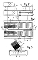
- the taping machine comprises, in known manner, a main frame 1, with a roller table 2 along which are moved forward the boxes S to be packaged.
- the sliding surface houses a conveyor 3, consisting for instance of a pair of dragging belts.
- the working bed 4 essentially consisting of a frame with a roller table, onto which are placed the open boxes - in the position indicated by 8, in figures 2 and 3 - to allow the operator to easily fill them.
- the bed 4 normally has its own support legs and is positioned to the side of the frame 1; however it can be directly fixed to said frame 1 by means of plates 4a and bofts, as shown in figures 1 and 2, this solution being adopted in particular with beds of smaller dimensions.
- a slide bar 5 with a T cross section is mounted along the main longitudinal axis of the bed 4 .
- said slide bar 5 is formed from bent plate, the central vertical portion of the T being of double plate, while the two horizontal branches of the T are of single plate.
- the slide bar 5 has an inlet end 5a, arranged between a starting position and an intermediate position of the bed 4 (as shown). Whereas, the other end 5b, or outlet end of the slide bar 5, extends beyond the bed 4 (see figure 1). In this way, when the bed 4 is to the side of the frame 1, or fixed thereto, the end 5b of the slide bar 5 extends as far as a position of the roller table 2 which is downstream of the starting point of the belt conveyor 3, and preferably also downstream of the starting point of the belt conveyor 3a It is thus clearly evident that the T-shaped slide bar 5 is positioned astride of the sliding surfaces of the bed 4 and of the taping machine.
- the vertical portion of the T of the slide bar 5 is housed into a central axial groove 6, formed both in the bed 4 and in the roller table 2.
- the horizontal branches of the T of said sliding bar 5 are in close proximity to the sliding surfaces for the boxes S.
- Figure 3 also shows the function of the T-shaped slide bar 5.
- the operator places a box S on the bed 4, he first of all folds the lower transversal flaps, positioning them flat on the bottom surface of the box; then, keeping the box in the inclined position S, he introduces one of the longitudinal flaps 8 under one of the horizontal branches 5' of the T, pressing the free edge of the flap 8 against the vertical portion of the T.
- he rotates the box anticlockwise in respect of figure 3 (arrow F), carrying also the other flap 8' of the box under the second branch 5" of the T, in the manner traced by the successive positions S., S,.
- the inlet end of the T-shaped slide bar is deprived of the branch 5", through an initial length A thereof, as clearly shown in figure 1.
- the flap 8 is actually inserted under the branch 5' when the box is first positioned on the bed 4 - and it is held thereunder, the flap 8' is positioned first of all on the roller table of the bed 4 , in correspondence of the end of the slide bar 5 deprived of the branch 5" (zone A), hence without being simultaneously introduced under the branch 5"; said introduction only takes place subsequently, as the operator provides to slightly push forward the box S in the direction of the arrow F' (figure 2).
- both branches 5' and 5" of the slide bar 5 have their edge corresponding to the inlet end, slightly oblique - as shown in figure 1 - to facilitate the above operation of initial introduction, while moving in the direction F'.
- the slide bar 5 is preferably pivoted, in correspondence of its inlet end, on the pin 9 which crosses the groove 6; the pivoting is obtained through a vertical slotted hole 10, allowing a certain slack in height of the bar 5, for an automatic adjustment to different thicknesses of the flaps 8, 8'.
- the slide bar 5 is essentially free to oscillate; spring means (not shown) are preferably connected to this outlet end, to impart a downward pull on the bar itself.
- this simple slide bar 5 guarantees, in a very efficient manner, a perfect guiding of the box S.
- the two opposed inner edges of the flaps 8, 8' rest against the vertical portion of the T of the bar 5, thereby making sure that the box is positively centred on the longitudinal axis of the machine.
- the engagement of the flaps 8, 8', under the branches 5' and 5", as well as the fact that the bar 5 is pushed downwardly by the aforementioned spring means guarantees a steady positioning of the box on the roller table and, in particular, on the belt conveyor 3.
- the fact that the bar 5 extends beyond the starting point of the belt conveyor 3, and preferably also beyond the starting point of the belt conveyor 3a, guarantees that the box is guided in a centred position - in its transfer from the bed to the taping machine - until it is safely and completely retained by the belt conveyors.
- the box S is abandoned by the bar 5 only when it is ' already clamped the means for applying the adhesive tape, namely, in a position where it can practically no longer be deviated from the correct rectilinear trajectory.
Landscapes
- Engineering & Computer Science (AREA)
- Mechanical Engineering (AREA)
- Package Closures (AREA)
- Auxiliary Devices For And Details Of Packaging Control (AREA)
- Basic Packing Technique (AREA)
Applications Claiming Priority (2)
| Application Number | Priority Date | Filing Date | Title |
|---|---|---|---|
| IT23570/84A IT1177189B (it) | 1984-11-14 | 1984-11-14 | Dispositivo di guida e di ritegno di scatole da imballare, in una macchina nastratrice da imballaggio |
| IT2357084 | 1984-11-14 |
Publications (1)
| Publication Number | Publication Date |
|---|---|
| EP0185906A1 true EP0185906A1 (en) | 1986-07-02 |
Family
ID=11208221
Family Applications (1)
| Application Number | Title | Priority Date | Filing Date |
|---|---|---|---|
| EP85114431A Withdrawn EP0185906A1 (en) | 1984-11-14 | 1985-11-13 | Device for guiding packaging boxes, in a taping machine and working bed assembly |
Country Status (5)
| Country | Link |
|---|---|
| EP (1) | EP0185906A1 (it) |
| JP (1) | JPS61178818A (it) |
| BR (1) | BR8505750A (it) |
| ES (1) | ES8700193A1 (it) |
| IT (1) | IT1177189B (it) |
Citations (4)
| Publication number | Priority date | Publication date | Assignee | Title |
|---|---|---|---|---|
| US2873039A (en) * | 1955-04-29 | 1959-02-10 | Adams Powel Equipment Ltd | Packing |
| DE2651413A1 (de) * | 1975-11-28 | 1977-06-08 | Augusto Marchetti | Maschine zum verschliessen parallelflachfoermiger schachteln von unterschiedlicher hoehe |
| US4041675A (en) * | 1976-06-07 | 1977-08-16 | The Loveshaw Corporation | Carton sealing machine carton setting up and loading equipment |
| US4398381A (en) * | 1980-12-24 | 1983-08-16 | Durable Packaging Corporation | Carton packing station fixture |
-
1984
- 1984-11-14 IT IT23570/84A patent/IT1177189B/it active
-
1985
- 1985-11-13 EP EP85114431A patent/EP0185906A1/en not_active Withdrawn
- 1985-11-14 ES ES549503A patent/ES8700193A1/es not_active Expired
- 1985-11-14 JP JP60253876A patent/JPS61178818A/ja active Pending
- 1985-11-14 BR BR8505750A patent/BR8505750A/pt unknown
Patent Citations (4)
| Publication number | Priority date | Publication date | Assignee | Title |
|---|---|---|---|---|
| US2873039A (en) * | 1955-04-29 | 1959-02-10 | Adams Powel Equipment Ltd | Packing |
| DE2651413A1 (de) * | 1975-11-28 | 1977-06-08 | Augusto Marchetti | Maschine zum verschliessen parallelflachfoermiger schachteln von unterschiedlicher hoehe |
| US4041675A (en) * | 1976-06-07 | 1977-08-16 | The Loveshaw Corporation | Carton sealing machine carton setting up and loading equipment |
| US4398381A (en) * | 1980-12-24 | 1983-08-16 | Durable Packaging Corporation | Carton packing station fixture |
Also Published As
| Publication number | Publication date |
|---|---|
| IT8423570A1 (it) | 1986-05-14 |
| IT8423570A0 (it) | 1984-11-14 |
| BR8505750A (pt) | 1986-08-12 |
| ES8700193A1 (es) | 1986-10-01 |
| JPS61178818A (ja) | 1986-08-11 |
| IT1177189B (it) | 1987-08-26 |
| ES549503A0 (es) | 1986-10-01 |
Similar Documents
| Publication | Publication Date | Title |
|---|---|---|
| US3583888A (en) | Packaging apparatus and method | |
| GB2139175A (en) | A machine for packing continuously moving articles with a strip of heat-shrinkable material | |
| DE3701273A1 (de) | Verfahren und vorrichtung zum verpacken von papier-taschentuechern | |
| EP0082348A2 (de) | Vorrichtung zum Einführen von Zigaretten-Gruppen in Zigaretten-Packungen | |
| US3350841A (en) | Carton folding and filling machine | |
| EP0478868A1 (en) | Apparatus for opening a flat tube and fitting same on a container or the like | |
| JPH1170600A (ja) | 箱状容器の底部に熱収縮性プラスチックフィルムを自動的に糊付けする方法と装置 | |
| US3902300A (en) | Flat folding and packaging apparatus and method | |
| US4505769A (en) | Method and apparatus for making a wrapper sleeve | |
| US2925695A (en) | Bag handling machines | |
| US5146728A (en) | Apparatus for the packaging of cigarettes | |
| JP2889968B2 (ja) | 包装方法およびその装置 | |
| DE69122587T2 (de) | Vorrichtung zum Füllen und Versiegeln von Beuteln | |
| US3002432A (en) | Packaging machine | |
| EP0192116B1 (de) | Seitenfaltungspacker für Zigarettenweichpackungen | |
| US2927411A (en) | Carton closing machine | |
| US3068622A (en) | Carton opening machine and method | |
| US2889675A (en) | Machine for covering containers | |
| US4131058A (en) | End tab folding mechanism for cartons | |
| JPH0659885B2 (ja) | 包装機 | |
| US3004478A (en) | Apparatus for forming cartons from carton blanks | |
| US5197259A (en) | Conveyor system and machine for applying tamper-evident bands to containers | |
| US2981043A (en) | Wrapping machine | |
| US3990163A (en) | Apparatus for the preparation of seams which are to be pressed | |
| US2050715A (en) | Banding and wrapping machine |
Legal Events
| Date | Code | Title | Description |
|---|---|---|---|
| PUAI | Public reference made under article 153(3) epc to a published international application that has entered the european phase |
Free format text: ORIGINAL CODE: 0009012 |
|
| AK | Designated contracting states |
Kind code of ref document: A1 Designated state(s): AT BE CH DE FR GB LI LU NL SE |
|
| STAA | Information on the status of an ep patent application or granted ep patent |
Free format text: STATUS: THE APPLICATION IS DEEMED TO BE WITHDRAWN |
|
| 18D | Application deemed to be withdrawn |
Effective date: 19870105 |
|
| RIN1 | Information on inventor provided before grant (corrected) |
Inventor name: LISSONI, ADELIO |