EP0185907A2 - Process for making a hinge seam for connecting the ends of a woven band together, and apparatus for carrying it out - Google Patents
Process for making a hinge seam for connecting the ends of a woven band together, and apparatus for carrying it out Download PDFInfo
- Publication number
- EP0185907A2 EP0185907A2 EP85114437A EP85114437A EP0185907A2 EP 0185907 A2 EP0185907 A2 EP 0185907A2 EP 85114437 A EP85114437 A EP 85114437A EP 85114437 A EP85114437 A EP 85114437A EP 0185907 A2 EP0185907 A2 EP 0185907A2
- Authority
- EP
- European Patent Office
- Prior art keywords
- fabric
- wire
- warp thread
- warp
- seam
- Prior art date
- Legal status (The legal status is an assumption and is not a legal conclusion. Google has not performed a legal analysis and makes no representation as to the accuracy of the status listed.)
- Granted
Links
Images


Classifications
-
- D—TEXTILES; PAPER
- D21—PAPER-MAKING; PRODUCTION OF CELLULOSE
- D21F—PAPER-MAKING MACHINES; METHODS OF PRODUCING PAPER THEREON
- D21F1/00—Wet end of machines for making continuous webs of paper
- D21F1/0027—Screen-cloths
- D21F1/0054—Seams thereof
Definitions
- the invention relates to a method for producing a plug-in seam for making a fabric band endless according to the preamble of claim 1 and claim 4. It also relates to a seaming machine for carrying out the method.
- the fabric belts of the type mentioned at the outset include, in particular, drainage or dryer fabrics.
- sieves with a plug seam have the advantage that they can be made endless in the dewatering machine or in the dry part of the paper machine even by joining the two prepared fabric ends with a plug wire.
- the production of these plug-in seams has so far been done by hand, by weaving or splicing back the warp wires on each fabric side of two fabric ends to be sewn, so that a row of warp wire loops is formed on each side, through which the common, connecting plug wire can then be guided.
- the object of the invention is therefore to provide a method and a machine that make it possible to mechanize or automate the cumbersome and time-consuming manual work and thereby a noticeable relief of the workforce and thus an increase in productivity and the quality of the plug to reach seams.
- the warp thread ends are lined up mechanically after the fraying of the right and left side of the fabric in a magazine band, separated individually according to the weaving order and alternately around one in the middle of the auxiliary warp bar, consisting of at least one wire
- Central wire of any cross-sectional area are returned and -woven so that the central wire is alternately wrapped by a warp thread end of the right and left fabric side according to the progress of work, while the opposite warp thread is woven back without wrapping the central wire, the warp thread ends after the entry in the Woven regulations corresponding open compartment are posted parallel to the selvedge.
- the method according to the invention consists in that the warp thread ends are lined up mechanically after fraying the right and left side of the fabric in a magazine band, separated according to the weaving order and individually woven back around a loop of a wire spiral, with the use of two wire spirals paralleling them and are not connected to one another, and the left and right ends of the fabric are held in such a way that lateral sliding or displacement is prevented.
- the wire spirals are then connected with a common jumper wire outside the sewing machine.
- a seam machine is used to carry out the method according to the invention, which is characterized by thread separators arranged on both sides of the plug-in seam to be produced, for separating and separating the warp threads ends from the warp threads arranged in magazine bundles on each side of the fabric, a gripper system consisting of transfer grippers and pull-through grippers for inserting the released individual threads into a weaving shed, which is formed by auxiliary warp threads by a shedding device, in which the individual threads can be attached to the respective fabric edge by a driven shed per half of the seam after striking, the individual threads can be weaved back into their own fabric side either by one or more central wires or wire spirals or by avoiding the central wire or wires.
- the sewing machine is mounted on a chassis 1, consisting of a frame body 31 which is movable on wheels 30 and which can be moved by a controlled drive motor 2 in the rhythm of the weaving progress.
- the frame body 31 is guided below the working plane of the machine on both sides on two parallel guide tubes 3, which in turn are attached at their ends to a horizontal cross member 32 of a stand 4. All other operating elements of the sewing machine according to the invention are also mounted on the chassis 1, not all of which are described in detail, since they are not necessary for understanding the workflow or the method.
- the shed forming device 5 as one of these operating elements is connected to the chassis via a console 6.
- the switching and monitoring devices necessary for operating the sewing machine which are not shown, are attached to the console 6.
- thread separators 7, 7 'and transfer grippers 8, 8' are fastened to the bracket 6 or to the shedding device 5 for both fabric halves or sides, the reference numerals provided with the line index referring to the one half of the fabric and the reference numbers not having the line index belong to the opposite other half of the tissue.
- the pull-through grippers 9, 9 'and the two weaving shutters 10, 10' are mounted below the working level of the sewing machine.
- the screen fabric 11 to be provided with a pin seam is carried out under the seaming machine, i.e. the machine rolls on the screen covered with a protective layer. Another possibility of guiding the screen fabric 11 is shown in FIG. 2.
- the screen fabric is then passed over the seaming machine like a tent via two support rods 23, 24.
- the two ends 21, 22 of the screen fabric 11 to be provided with a pin seam are prepared before insertion into the seaming machine as far as the weft threads are removed in an area of approximately 10 to 20 cm width and then, depending on the weave, 10 to 30 weft threads on the Warp thread ends 12, 12 'can be combined in their exact weaving position to form a magazine band 13, 13'.
- the magazines 13, 13 ' are fastened to the end stands 4, 4' of the chassis, of which only one is shown in FIG. 1, by means of a clamping device 14.
- a wire bundle which can consist of original weft threads of the fabric or a strip 15, 15 ', also called auxiliary warp strip, which consists of original weft threads of the fabric and which represents the chain for the seam weaving process which runs transverse to the actual direction of sieving.
- the central wire 16 is located exactly in the middle between the two auxiliary chain strips 15, 15 '.
- the auxiliary warp strips and the central wire are fastened in a further tensioning device 17 of the machine, which is also carried by the stands 4, 4 '.
- the individual wires of the auxiliary chain and the central wire are guided in the eyelets of the shedding device 5, which is located above or below the weaving plane on the chassis.
- the separation and separation of the warp thread ends 12, 12 '(FIG. 1) with the aid of the thread separators 7, 7' is carried out in a manner known per se, with seam-forming elements of the same type on both sides, such as thread separators 7,7 ', transfer hooks 8,8', Pull-through grippers 9.9 'and weaving frames 10.10' are provided.
- the transfer rapier 8 takes over the warp thread separated by the thread separator 7' and swings it down into the transfer position of the working plane, as can be seen in FIG. 3.
- the pull-through gripper 9 takes over the warp thread end and pulls the warp thread into the full compartment formed by the shedding device 5.
- the warp thread end thus entered is then struck against the selvedge by the sley 10 '.
- a partial compartment is now formed from the left part of the auxiliary warp strip 15 ', as can be seen in FIG. 4, and the same end of the warp thread is pivoted back by the pull-through gripper 9 into the transfer position mentioned, where it is taken over by the pull-through gripper 9', with the hand-over gripper 8 'during the transfer process positioning aid by pressing of the warp thread.
- the central wire 16 Since the central wire 16 is not involved in the change of subject during these operations, it is not wrapped around by the warp wire ends. This is shown in Fig. 6 by the threads or wires a and b. Thereafter, the operations described above are repeated in the same order with the following wires or threads b and d, but this time the central wire 16 is included in the change of subject and thus in the warp wire loop. Thus, only every second warp thread of each fabric end forms a load-bearing warp wire loop 33, 33 'which can transmit longitudinal forces.
- plug wire 16 instead of a single central wire 16, it is also possible to weave in several parallel juxtaposed plug wires, for example two plug wires 27, 27 ', as shown in FIG. 7, which increases the seam strength because all the warp threads of the fabric protrude in contrast to the one shown in FIG. 6 Seam.
- the use of two plug wires takes into account in particular the fact that with a frequently used four-ply, so-called double-layer fabric, the loops due to the natural thread offset turn out to be alternately long and short, as shown schematically in FIG. 7 for a simple tissue.
- the two fabric ends 15, 15 ' are offset from one another such that a long loop 28 of the left screen fabric edge with a short loop 29' of the right screen fabric edge around the right plug wire 27 'and a short loop 29 of the left screen fabric edge with a long loop 28 'of the right sieve mesh around the left plug wire 27 can be combined.
- a process variant can be used in such a way that the warp thread ends are individually woven into a loop 34 of a wire spiral 25 after the fraying of the right and left side of the fabric and their alignment in the magazine band each warp wire end binds into the spiral, as shown in Fig. 8.
- This device is required in particular when using two parallel wire spirals 25, 25 ', one of which is assigned to a screen fabric side. These two wire spirals are not connected to each other.
- the left and right tissue ends are held by the device 18 by means of guide rollers 19, 20 in such a way that lateral slipping or displacement is prevented. Then the wire spirals are connected with a common plug wire outside of the sewing machine.
- the seaming machine described above is designed in such a way that it can also weave a wire spiral 25 of the type shown in FIG. 8 into only one side of the fabric.
- a wire spiral 25 of the type shown in FIG. 8 into only one side of the fabric.
- the wire spirals which are later connected to a common plug wire when the screen is made endless, together with a wire 26 (FIG. 10) lying in the spirals into the fabric ends.
- the sewing machine is suitable for technical fabrics such as To equip dryer fabrics for drainage, paper and board machines of various compositions in warp and weft directions (mono or multifilament in polyester or polyamide) and single or multi-layer construction with push-in seams.
- Basic fabrics for wet felts in single or multi-layer designs can also be provided with pin seams.
- the auxiliary warp threads in the seam region that is to say the weft threads in the original fabric, are made of a different material than the other weft threads in the fabric.
Landscapes
- Woven Fabrics (AREA)
- Paper (AREA)
- Treatment Of Fiber Materials (AREA)
- Light Receiving Elements (AREA)
- Heterocyclic Carbon Compounds Containing A Hetero Ring Having Nitrogen And Oxygen As The Only Ring Hetero Atoms (AREA)
- Solid State Image Pick-Up Elements (AREA)
Abstract
Die Erfindung betrifft ein Verfahren zur Herstellung einer Stecknaht zum Endlosmachen eines Gewebebandes, insbesondere eines Siebes, bei dem die Kettfadenenden einer jeden Gewebeseite mit einem Hilfskettstreifen verwoben werden sowie eine Nahtungsmaschine zur Durchführung des Verfahrens. Um die bisher übliche umständliche und zeitaufwendige Handarbeit bei der Herstellung der Stecknaht zu mechanisieren bzw. zu automatisieren und dadurch eine spürbare Entlastung des Arbeitspersonals und damit eine Steigerung der Produktivität sowie der Qualität der Stecknähte zu erreichen, wird vorgeschlagen, daß die Kettfadenenden maschinell nach dem Ausfransen der rechten und linken Gewebeseite in einem Magazinierbund aufgereiht, einzeln entsprechend der Webordnung abgetrennt und abwechselnd um einen in der Mitte des Hilfskettstreifens angeordneten, aus wenigstens einem Draht bestehenden Zentraldraht beliebiger Querschnittsfläche herum zurückgeführt und -gewoben werden, so daß der Zentraldraht entsprechend dem Arbeitsfortschritt abwechselnd von einem Kettfadenende der rechten und linken Gewebeseite umschlungen wird, während der jeweils gegenüberliegende Kettfaden ohne Umschlingung des Zentraldrahtes zurückgewoben wird, wobei die Kettfadenenden nach dem Eintrag in das der Webordnung entsprechende offene Fach parallel zur Webkante angeschlagen werden.
Description
Die Erfindung betrifft ein Verfahren zur Herstellung einer Stecknaht zum Endlosmachen eines Gewebebandes gemäß dem Oberbegriff des Anspruchs 1 und des Anspruchs 4. Sie betrifft ferner eine Nahtungsmaschine zur Durchführung des Verfahrens.The invention relates to a method for producing a plug-in seam for making a fabric band endless according to the preamble of claim 1 and claim 4. It also relates to a seaming machine for carrying out the method.
Zu den Gewebebändern der eingangs genannten Art gehören insbesondere Entwässerungs- oder Trockensiebe. Gegenüber endlos gewobenen oder durch eine Webnaht endlos gemachten Sieben haben Siebe mit Stecknaht den Vorteil, daß sie in der Entwässerungsmaschine oder im Trockenteil der Papiermaschine selbst durch Zusammenfügen der beiden vorbereiteten Gewebeenden mit einem Steckdraht endlos gemacht werden können. Die Herstellung dieser Stecknähte ist bisher von Hand erfolgt, indem die Kettdrähte einer jeden Gewebeseite zweier zu vernahtender Gewebeenden zurückgewoben oder -zurückgespleißt werden, so daß auf jeder Seite eine Reihe von Kettdrahtschlaufen entsteht, durch die dann der gemeinsame, verbindene Steckdraht geführt werden kann.The fabric belts of the type mentioned at the outset include, in particular, drainage or dryer fabrics. Compared to endlessly woven or made endless by a woven seam, sieves with a plug seam have the advantage that they can be made endless in the dewatering machine or in the dry part of the paper machine even by joining the two prepared fabric ends with a plug wire. The production of these plug-in seams has so far been done by hand, by weaving or splicing back the warp wires on each fabric side of two fabric ends to be sewn, so that a row of warp wire loops is formed on each side, through which the common, connecting plug wire can then be guided.
Die Herstellung einer solchen Stecknaht von Hand ist ähnlich aufwendig wie in der EP 00 43 441 oder im DE-GM 81 22 451 für das Endlosmachen von Entwässerungssieben mit einer Webnaht beschrieben wird.The production of such a plug-in seam by hand is similarly complex as described in EP 00 43 441 or in DE-GM 81 22 451 for the continuous making of drainage sieves with a woven seam.
Die Aufgabe der Erfindung besteht deshalb darin, ein Verfahren sowie eine Maschine zu schaffen, die es ermöglichen, die umständliche und zeitaufwendige Handarbeit zu mechanisieren bzw. zu automatisieren und dadurch eine spürbare Entlastung des Arbeitspersonals und damit eine Steigerung der Produktivität sowie der Qualität der Stecknähte zu erreichen.The object of the invention is therefore to provide a method and a machine that make it possible to mechanize or automate the cumbersome and time-consuming manual work and thereby a noticeable relief of the workforce and thus an increase in productivity and the quality of the plug to reach seams.
Diese Aufgabe wird nach der Erfindung gemäß einem Vorschlag dadurch gelöst, daß die Kettfadenenden maschinell nach dem Ausfransen der rechten und linken Gewebeseite in einem Magazinierbund aufgereiht, einzeln entsprechend der Webordnung abgetrennt und abwechselnd um einen in der Mitte des Hilfskettsteifens angeordneten, aus wenigstens einem Draht bestehenden Zentraldraht beliebiger Querschnittsfläche herum zurückgeführt und -gewoben werden, so daß der Zentraldraht entsprechend dem Arbeitsfortschritt abwechselnd von einem Kettfadenende der rechten und linken Gewebeseite umschlungen wird, während der jeweils gegenüberliegende Kettfaden ohne Umschlingung des Zentraldrahtes zurückgewoben wird, wobei die Kettfadenenden nach dem Eintrag in das der Webordnung entsprechende offene Fach parallel zur Webkante angeschlagen werden.This object is achieved according to the invention in accordance with a proposal in that the warp thread ends are lined up mechanically after the fraying of the right and left side of the fabric in a magazine band, separated individually according to the weaving order and alternately around one in the middle of the auxiliary warp bar, consisting of at least one wire Central wire of any cross-sectional area are returned and -woven so that the central wire is alternately wrapped by a warp thread end of the right and left fabric side according to the progress of work, while the opposite warp thread is woven back without wrapping the central wire, the warp thread ends after the entry in the Woven regulations corresponding open compartment are posted parallel to the selvedge.
Gemäß einem anderen Lösungsvorschlag besteht das erfindungsgemäße Verfahren darin, daß die Kettfadenenden maschinell nach dem Ausfransen der rechten und linken Gewebeseite in einem Magazinierbund aufgereiht, entsprechend der Webordnung abgetrennt und einzeln jeweils um eine Schlinge einer Drahtspirale zurückgewoben werden, wobei bei Verwendung von zwei Drahtspiralen diese parallel liegen und nicht miteinander verbunden sind, und wobei'das linke und das rechte Gewebeende so festgehalten .erden, daß ein seitliches Verrutschen oder Verschieben verhindert wird. Die Drahtspiralen werden danach mit einem gemeinsamen Steckdraht außerhalb der Nahtungsmaschine verbunden.According to another proposed solution, the method according to the invention consists in that the warp thread ends are lined up mechanically after fraying the right and left side of the fabric in a magazine band, separated according to the weaving order and individually woven back around a loop of a wire spiral, with the use of two wire spirals paralleling them and are not connected to one another, and the left and right ends of the fabric are held in such a way that lateral sliding or displacement is prevented. The wire spirals are then connected with a common jumper wire outside the sewing machine.
Zur Durchführung des erfindungsgemäßen Verfahrens dient eine Nahtungsmaschine, die sich kennzeichnet durch beidseitig der herzustellenden Stecknaht angeordnete Fadentrenner zur Abtrennung und Vereinzelung der Kettfadenenden aus den in Magazinierbunden angeordneten Kettfäden jeder Gewebeseite, ein aus Obergabegreifern und Durchziehgreifern bestehendes Greifersystem zum Eintragen der ausgelösten Einzelfäden in ein von Hilfskettfäden durch eine Fachbildungseinrichtung vorgebildetes Webfach, in dem die Einzelfäden durch eine angetriebene Weblade pro Nahthälfte an die jeweilige Gewebekante anschlagbar sind, wobei nach dem Anschlagen die Einzelfäden durch das Greifersystem entweder um einen oder mehrere Zentraldrähte bzw. Drahtspiralen herum oder unter Vermeidung des oder der Zentraldrähte bzw. Drahtspiralen in ihre eigene Gewebeseite zurückwebbar sind.A seam machine is used to carry out the method according to the invention, which is characterized by thread separators arranged on both sides of the plug-in seam to be produced, for separating and separating the warp threads ends from the warp threads arranged in magazine bundles on each side of the fabric, a gripper system consisting of transfer grippers and pull-through grippers for inserting the released individual threads into a weaving shed, which is formed by auxiliary warp threads by a shedding device, in which the individual threads can be attached to the respective fabric edge by a driven shed per half of the seam after striking, the individual threads can be weaved back into their own fabric side either by one or more central wires or wire spirals or by avoiding the central wire or wires.
Weitere vorteilhafte Ausgestaltungen der Erfindung sind in den Unteransprüchen gekennzeichnet.Further advantageous embodiments of the invention are characterized in the subclaims.
Die Erfindung wird nachfolgend anhand der in der Zeichnung -dargestellten Ausführungsbeispiele näher erläutert. In der Zeichnung zeigen:
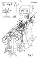
- Fig. 1 eine schematische, isometrische Ansicht der erfindungsgemäßen Nahtungsmaschine von vorm,
- Fig. 2 eine Stirnansicht der Maschine von Fig. 1 in einem kleineren Maßstab, wobei die endlose zu machende Gewebebahn zeltartig über die Nahtungsmaschine hinweggeführt ist,
- Fig. 3-5 schematische Darstellungen der Arbeitsschritte bei der Herstellung der Stecknaht für eine Gewebeseite,
- Fig. 6 eine schematische Draufsicht des Magazinierbundes der mittels eines Zentraldrahtes miteinander zu verbindenden rechten und linken Gewebeseite,
- Fig. 7 eine der Fig.6 entsprechende Draufsicht, bei der jedoch anstelle eines Zentraldrahtes zwei parallele Steckdrähte Verwendung finden,
- Fig. 8 die Draufsicht eines Gewebeendes, in das eine Drahtspirale eingewoben ist, wobei jedes Kettdrahtende in die Spirale einbindet,
- Fig. 9 eine Querschnittsansicht zweier mit je einer Drahtspirale versehener Gewebeenden, die durch eine mit Führungsrollen versehene Vorrichtung positioniert werden und
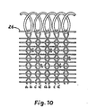
- Fig. 10 eine der Fig.8 ähnliche Draufsicht eines Gewebeendes, bei der die Drahtspirale zusammen mit einem in ihr liegenden Draht eingewoben ist.
- 1 is a schematic, isometric view of the seam machine according to the invention from vorm,
- 2 shows a front view of the machine of FIG. 1 on a smaller scale, the endless fabric web to be made being guided over the seaming machine like a tent,
- 3-5 schematic representations of the working steps in the production of the plug seam for a fabric side,
- 6 shows a schematic top view of the magazine bundle of the right and left side of the tissue to be connected to one another by means of a central wire,
- 7 shows a top view corresponding to FIG. 6, but in which two parallel plug-in wires are used instead of a central wire,
- 8 shows the top view of a fabric end into which a wire spiral is woven, each warp wire end being integrated into the spiral,
- 9 shows a cross-sectional view of two fabric ends, each provided with a wire spiral, which are positioned by a device provided with guide rollers, and
- 10 shows a plan view of a fabric end similar to FIG. 8, in which the wire spiral is woven together with a wire lying in it.
Wie aus Fig. 1 ersichtlich, ist die Nahtungsmaschine auf einem Fahrwerk 1 montiert, bestehend aus einem auf Rädern 30 beweglichen Rahmenkörper 31, der sich im Rhythmus des Webfortschrittes über einen gesteuerten Antriebsmotor 2 fortbewegen läßt. Der Rahmenkörper 31 wird unterhalb der Arbeitsebene der Maschine auf beiden Seiten auf zwei parallelen Führungsrohren 3 geführt, die wiederum an ihren Enden an einer waagrechten Traverse 32 eines Ständers 4 befestigt sind. Auf dem Fahrgestell 1 sind auch alle anderen Betriebselemente der erfindungsgemäßen Nahtungsmaschine angebracht, die nicht alle im einzelnen beschrieben werden, da sie zum Verständnis des Arbeitsablaufes bzw. des Verfahrens nicht erforderlich sind.As can be seen from FIG. 1, the sewing machine is mounted on a chassis 1, consisting of a
Die Fachbildungseinrichtung 5 als eines dieser Betriebselemente ist über eine Konsole 6 mit dem Fahrgestell verbunden.The shed forming device 5 as one of these operating elements is connected to the chassis via a
An der Konsole 6 sind die zur Bedienung der Nahtungsmaschine notwendigen Schalt- und Oberwachungseinrichtungen angebracht, die nicht dargestellt sind. Darüberhinaus sind an der Konsole 6 bzw. an der Fachbildungseinrichtung 5 für beide Gewebehälften bzw. -seiten Fadentrenner 7, 7' und Obergabegreifer 8, 8' befestigt, wobei die mit dem Strichindex versehenen Bezugszeichen zu der einen Gewebehälfte und die keinen Strichindex aufweisenden Bezugszeichen zu der gegenüberliegenden anderen Gewebehälfte gehören. Unterhalb der Arbeitsebene der Nahtungsmaschine sind die Durchziehgreifer 9,9' sowie die beiden Webladen 10, 10' gelagert.The switching and monitoring devices necessary for operating the sewing machine, which are not shown, are attached to the
In Fig. 1 ist das mit einer Stecknaht zu versehende Siebgewebe 11 unter der Nahtungsmaschine durchgeführt, d.h. die Maschine rollt auf dem mit einer Schutzschicht abgedeckten Sieb. Eine andere Möglichkeit der Führung des Siebgewebes 11 zeigt Fig. 2. Danach wird das Siebgewebe zeltartig über zwei Tragstangen 23,24 über die Nahtmaschine hinweggeführt.In Fig. 1, the
Die beiden Enden 21,22 des mit einer Stecknaht zu versehenden Siebgewebes 11 werden vor dem Einlegen in die Nahtungsmaschine soweit vorbereitet, als in einem Bereich von ca. 10 bis 20 cm Breite die Schußfäden entfernt und danach je nach Gewebebindung 10 bis 30 Schußfäden auf den Kettfadenenden 12,12' in ihrer genauen Webposition zu einem Magazinierbund 13,13' zusammengefaßt werden. Die Magazinierbunde 13,13' sind an den endseitigen Ständern 4, 4' des Fahrgestells, von denen in Fig. 1 nur der eine dargestellt ist, mittels einer Klemmvorrichtung 14 befestigt.The two
Vor Beginn der Nahtung liegt zwischen den beiden ausgefransten Enden des Siebgewebes 11, die von den Magazinierbunden 13,13' gehalten werden, zu beiden Seiten des Drahtes 16, der als Zentraldraht zu bezeichnen ist, ein Drahtbündel, das aus Original Schußfäden des Gewebes bestehen kann oder ein aus Originalschußfäden des Gewebes bestehender Streifen 15, 15', auch Hilfskettstreifen genannt, der für den quer zur eigentlichen Siebrichtung verlaufenden Nahtwebprozeß die Kette darstellt. Der Zentraldraht 16 befindet sich genau in der Mitte zwischen den beiden Hilfskettstreifen 15,15'. Die Hilfskettstreifen und der Zentraldraht sind in einer weiteren Spanneinrichtung 17 der Maschine befestigt, die ebenfalls von den Ständern 4, 4' getragen wird.Before the start of the seam lies between the two frayed ends of the
Die Einzeldrähte der Hilfskette sowie der Zentraldraht werden in ösen der Fachbildungseinrichtung 5, die sich oberhalb oder unterhalb der Webebene am Fahrgestell befindet, geführt. Die Abtrennung und Vereinzelung der Kettfadenenden 12, 12' (Fig.1) mit Hilfe der Fadentrenner 7,7' erfolgt in an sich bekannter Weise, wobei beidseitig der Naht gleichartige Nahtbildungselemente, wie Fadentrenner 7,7', Obergabegreifer 8,8', Durchziehgreifer 9,9' und Webladen 10,10' vorgesehen sind. Dabei übernimmt zunächst der Obergabegreifer 8' den vom Fadentrenner 7' vereinzelten Kettfaden und schwingt ihn nach unten in die übergabeposition der Arbeitsebene, wie aus Fig. 3 ersichtlich. Danach übernimmt der Durchziehgreifer 9 das Kettfadenende und zieht den Kettfaden in das durch die Fachbildungseinrichtung 5 gebildete Vollfach. Daraufhin wird das so eingetragene Kettfadenende durch die Weblade 10' an die Webkante angeschlagen. Nunmehr wird vom linken Teil des Hilfskettstreifens 15' ein Teilfach gebildet, wie aus Fig.4 ersichtlich und dasselbe Kettfadenende vom Durchziehgreifer 9 in die genannte Übergabeposition zurückgeschwenkt, wo es der Durchziehgreifer 9' übernimmt, wobei der Obergabegreifer 8' während des Obergabevorgangs Positionierungshilfe durch Andrücken des Kettfadens leistet. Der Durchziehgreifer 9' spannt danach das Kettfadenende an, woraufhin wiederum die Weblade 10' angeschlagen wird. Danach wird das Anschlußteilfach in der Hilfskettfadenhälfte 15' gebildet, der nächste Kettfaden vom Obergabegreifer 8' in die Obergabeposition gebracht und vom Durchziehgreifer 9 in das nun aussenliegende Teilfach eingetragen, wie aus Fig. 5 ersichtlich, wonach mit der Weblade 10' wiederum der Kettfaden angeschlagen wird.The individual wires of the auxiliary chain and the central wire are guided in the eyelets of the shedding device 5, which is located above or below the weaving plane on the chassis. The separation and separation of the warp thread ends 12, 12 '(FIG. 1) with the aid of the
Da bei diesen Arbeitsgängen der Zentraldraht 16 am Fachwechsel nicht beteiligt ist, wird er von den Kettdrahtenden auch nicht umschlungen. Dies wird in Fig. 6 durch die Fäden oder Drähte a und b dargestellt. Danach wiederholen sich die im obigen beschriebenen Arbeitsgänge in derselben Reihenfolge mit den Folgedrähten oder -fäden b und d, wobei diesmal jedoch der Zentraldraht 16 in den Fachwechsel und damit in die Kettdrahtschlaufe einbezogen wird. Somit bildet nur jeder zweite Kettfaden eines jeden Gewebeendes eine tragende Kettdrahtschlaufe 33,33', die Längskräfte übertragen kann.Since the
Anschließend werden auf der anderen Hälfte 15 des Hilfskettstreifens die entsprechenden Arbeitsgänge wiederholt, wobei diesmal der Anschlag durch die Weblade 10 erfolgt, und die Drähte oder Fäden e, f sowie g, h eingetragen werden, wie in Fig. 6 dargestellt. Der Aufbau der beiden Webladen 10,10' ist an sich bekannt und wird daher hier nicht näher erläutert.The corresponding operations are then repeated on the
Anstelle eines einzigen Zentraldrahtes 16 lassen sich auch mehrere parallel nebeneinanderliegende Steckdrähte einweben, so beispielsweise zwei Steckdrähte 27,27', wie in Fig. 7 dargestellt, wodurch die Nahtfestigkeit vergrößert wird weil alle Kettfäden des Gewebes mitragen im Gegensatz zu der in Fig. 6 dargestellten Naht. Die Verwendung von zwei Steckdrähten trägt insbesondere der Tatsache Rechnung, daß bei einem häufig benutzten vierschäftigen, sogenannten doppellagigen Gewebe die Schlaufen aufgrund der natürlichen Fadenkröpfung abwechselnd lang und kurz ausfallen, wie in Fig. 7 schematisch für ein einfaches Gewebe dargestellt. Die beiden Gewebeenden 15,15' sind dabei so gegeneinander versetzt angeordnet, daß jeweils eine lange Schlaufe 28 des linken Siebgeweberandes mit einer kurzen Schlaufe 29' des rechten Siebgeweberandes um den rechten Steckdraht 27' und eine kurze Schlaufe 29 des linken Siebgeweberandes mit einer langen Schlaufe 28' des rechten Siebgeweberandes um den linken Steckdraht 27 vereinigt werden.Instead of a single
Um den Vorteil der vollen Nahtfestigkeit auf andere Weise zu erreichen, kann gemäß einer Verfahrensvariante so gearbeitet werden, daß die Kettfadenenden nach dem Ausfransen der rechten und linken Gewebeseite und ihrer Aufreihung in dem Magazinierbund einzeln jeweils in eine Schlinge 34 einer Drahtspirale 25 eingewoben werden, wobei jedes Kettdrahtende in die Spirale einbindet, wie aus Fig. 8 ersichtlich. Dabei hat es sich als zweckmässig erwiesen, die mit der eingewobenen Spirale 25 versehenen Siebgewebeenden 15,15' in einer in Fig. 9 dargestellten Vorrichtung 18 zu führen, die im Fahrgestell 1 der Nahtungsmaschine gelagert ist. Diese Vorrichtung wird insbesondere bei Verwendung von zwei parallelen Drahtspiralen 25,25' benötigt, von denen jeweils eine einer Siebgewebeseite zugeordnet ist. Diese beiden Drahtspiralen sind nicht miteinander verbunden. Das linke und das rechte Gewebeende werden durch die Vorrichtung 18 mittels Führungsrollen 19,20 so festgehalten, daß ein seitliches Verrutschen oder Verschieben verhindert wird. Danach werden die Drahtspiralen mit einem gemeinsamen Steckdraht außerhalb der Nahtungsmaschine verbunden.In order to achieve the advantage of full seam strength in a different way, a process variant can be used in such a way that the warp thread ends are individually woven into a
Bei Verwendung eines gemeinsamen Steck- oder Zentraldrahtes ist eine Führungsvorrichtung der in Fig. 9 gezeigten Art nicht erforderlich, da durch den gemeinsamen Zentraldraht eine ausreichende Lagestabilität sichergestellt wird.When using a common plug or central wire, a guide device of the type shown in Fig. 9 not necessary because the common central wire ensures sufficient positional stability.
Die im obigen beschriebene Nahtungsmaschine ist steuerungsmässig so ausgelegt, daß sie auch in nur eine Gewebeseite eine Drahtspirale 25 der in Fig. 8 gezeigten Art einweben kann. Schließlich ist auch die Möglichkeit gegeben, die Drahtspiralen,die später beim Endlosmachen des Siebes mit einem gemeinsamen Steckdraht verbunden werden, zusammen mit einem in den Sprialen liegenden Draht 26 (Fig.10) in die Gewebeenden einzuweben.In terms of control, the seaming machine described above is designed in such a way that it can also weave a
Die Nahtungsmaschine ist geeignet, technische Gewebe, wie z.B. Trockensiebe für Entwässerungs-, Papier- und Kartonmaschinen unterschiedlichster Zusammensetzung in Kett- und Schußrichtung (Mono- oder Multifil in Polyester oder Polyamid) und ein- oder mehrlagiger Konstruktion mit Stecknähten auszurüsten. Ebenso können Basisgewebe für Naßfilze in ein- oder mehrlagiger Ausführung mit Stecknähten versehen werden.The sewing machine is suitable for technical fabrics such as To equip dryer fabrics for drainage, paper and board machines of various compositions in warp and weft directions (mono or multifilament in polyester or polyamide) and single or multi-layer construction with push-in seams. Basic fabrics for wet felts in single or multi-layer designs can also be provided with pin seams.
Aus Gründen der Permeabilitätsbeeinflussung kann es in einzelnen Fällen vorteilhaft sein, wenn im Nahtbereich die Hilfskettfäden, also im Originalgewebe die Schußfäden, aus einem anderen Material bestehen als die übrigen Schußfäden im Gewebe.For reasons of influencing permeability, it can be advantageous in individual cases if the auxiliary warp threads in the seam region, that is to say the weft threads in the original fabric, are made of a different material than the other weft threads in the fabric.
Claims (6)
Priority Applications (1)
| Application Number | Priority Date | Filing Date | Title |
|---|---|---|---|
| AT85114437T ATE47164T1 (en) | 1984-12-21 | 1985-11-13 | PROCESS FOR MAKING A STITCHING SEAM FOR ENDING A FABRIC TAPE AND SUITTING MACHINE. |
Applications Claiming Priority (2)
| Application Number | Priority Date | Filing Date | Title |
|---|---|---|---|
| DE19843446941 DE3446941A1 (en) | 1984-12-21 | 1984-12-21 | METHOD FOR THE PRODUCTION OF A STITCH SEAM TO ENDLESS A TEXTILE TAPE AND SEWING MACHINE |
| DE3446941 | 1984-12-21 |
Publications (4)
| Publication Number | Publication Date |
|---|---|
| EP0185907A2 true EP0185907A2 (en) | 1986-07-02 |
| EP0185907A3 EP0185907A3 (en) | 1987-06-24 |
| EP0185907B1 EP0185907B1 (en) | 1989-10-11 |
| EP0185907B2 EP0185907B2 (en) | 1998-04-29 |
Family
ID=6253575
Family Applications (1)
| Application Number | Title | Priority Date | Filing Date |
|---|---|---|---|
| EP85114437A Expired - Lifetime EP0185907B2 (en) | 1984-12-21 | 1985-11-13 | Apparatus for making a hinge seam |
Country Status (7)
| Country | Link |
|---|---|
| US (2) | US4985970A (en) |
| EP (1) | EP0185907B2 (en) |
| JP (1) | JPS61194269A (en) |
| AT (1) | ATE47164T1 (en) |
| DE (2) | DE3446941A1 (en) |
| FI (1) | FI79562C (en) |
| NO (1) | NO855104L (en) |
Cited By (3)
| Publication number | Priority date | Publication date | Assignee | Title |
|---|---|---|---|---|
| WO1994021847A1 (en) * | 1993-03-19 | 1994-09-29 | Jwi Ltd. | High loop density pin seam |
| US7005041B2 (en) | 2002-04-25 | 2006-02-28 | Heimbach Gmbh & Co. | Paper machine belt and method for creating a connection of the end edges of such a paper machine belt |
| US7381306B2 (en) | 2004-03-12 | 2008-06-03 | Heimbach Gmbh & Co | Paper machine belt |
Families Citing this family (25)
| Publication number | Priority date | Publication date | Assignee | Title |
|---|---|---|---|---|
| DE3733120A1 (en) * | 1987-09-30 | 1989-04-13 | Wangner Gmbh Co Kg Hermann | AUXILIARY DEVICE ON A SEAMING MACHINE FOR ENDLESSING FLAT-WOVEN PLASTIC SCREENS BY MEANS OF A WEAVE SEAM |
| US5258652A (en) * | 1988-01-08 | 1993-11-02 | Hitachi, Ltd. | Distributed plant control system |
| DE3823715A1 (en) * | 1988-07-13 | 1990-01-18 | Oberdorfer Fa F | METHOD FOR THE PRODUCTION OF A STITCH SEAM TO ENDLESS A TEXTILE TAPE AND SEWING MACHINE |
| JPH02115598U (en) * | 1989-02-28 | 1990-09-17 | ||
| US5167262A (en) * | 1991-02-22 | 1992-12-01 | Asten Group, Inc. | Join length for endless flat woven papermakers fabric |
| JPH0571036A (en) * | 1991-09-10 | 1993-03-23 | Nippon Filcon Co Ltd | Device for shed using heald having one supported end and method for weaving and joining using the same device |
| US5494080A (en) * | 1991-09-10 | 1996-02-27 | Nippon Filcon Co., Ltd. | Arcuate heddle and shedding system employing an arcuate heddle |
| DE9215498U1 (en) * | 1992-11-13 | 1994-03-17 | Novatech GmbH Siebe und Technologie für Papier, 72760 Reutlingen | Pull-through gripper for inserting an auxiliary weft thread into the seam weaving compartment in a seam weaving machine |
| DE9301722U1 (en) * | 1993-02-08 | 1994-06-09 | Novatech GmbH Siebe und Technologie für Papier, 72760 Reutlingen | Seam weaving machine with fringe catcher |
| US5390708A (en) * | 1993-09-21 | 1995-02-21 | Asten Group, Inc. | Apparatus for translating yarns in the proper position and orientation for forming a woven join |
| US5488976A (en) * | 1994-03-16 | 1996-02-06 | Asten, Inc. | Coil seam for single layer industrial fabrics having an uneven shed pattern |
| DE19505280C2 (en) * | 1995-02-16 | 1998-08-06 | Staeubli Gmbh | Method and device for the mechanical production of a seam for making a web of fabric endless |
| US5738151A (en) * | 1996-08-13 | 1998-04-14 | Asten, Inc. | Seam loop formation device and method of operation |
| US6014797A (en) * | 1997-06-16 | 2000-01-18 | Jwi Ltd. | Method and apparatus for unravelling threads |
| US6016851A (en) * | 1998-10-16 | 2000-01-25 | Wis Seaming Equipment, Inc. | Method and apparatus for providing the warp thread end of a fabric ribbon |
| DE19944864C2 (en) | 1999-09-18 | 2003-03-06 | Heimbach Gmbh Thomas Josef | Belt for circulation in machines and process for its production |
| US6500369B1 (en) * | 1999-10-14 | 2002-12-31 | Janusz P. Gorowicz | Method of making a headliner having integrated energy absorbing foam |
| US6554029B1 (en) * | 2000-05-26 | 2003-04-29 | Wagner Finckh Gmbh | Method for mounting a new harness on a seam weaving machine, apparatus for making a flat woven fabric endless and harness carriage |
| JP4400925B2 (en) * | 2004-08-23 | 2010-01-20 | 日本フイルコン株式会社 | Industrial two-layer fabric |
| JP4481765B2 (en) * | 2004-08-23 | 2010-06-16 | 日本フイルコン株式会社 | Industrial two-layer fabric |
| US7168456B1 (en) * | 2005-10-26 | 2007-01-30 | North Rocky Robot Technology, Inc. (Nortec) | Method and apparatus to remove yarns from the fringes of an industrial textile |
| DE202005018856U1 (en) * | 2005-12-01 | 2007-04-12 | Wangner Gmbh & Co Kg | Holder for the weaving reed of a seam loom, to roll the seam weft thread either by means of oblique position of the reed or movable roller |
| AT503434B1 (en) * | 2006-06-29 | 2007-10-15 | Wis Engineering Gmbh & Co Kg | Apparatus for removing weft threads from fabric edge, to allow formation of endless belt with woven seam, comprises catching device for stripping weft threads and stripped thread take-off device |
| FI3759277T3 (en) | 2018-10-10 | 2023-02-28 | Pintle insertion tool | |
| CN117867842B (en) * | 2024-01-22 | 2025-11-21 | 聊城经纬工业网毯有限公司 | Plug-in machine for producing bottom net of papermaking clothing |
Family Cites Families (11)
| Publication number | Priority date | Publication date | Assignee | Title |
|---|---|---|---|---|
| US2786256A (en) * | 1953-10-30 | 1957-03-26 | Axelsson Axel | Apparatus for tying threads in a cloth joining operation |
| DE1207783B (en) * | 1962-06-22 | 1965-12-23 | Karl Ulrich Schuster | Process for the production of the transverse seam for making paper machine screens endless with a plastic chain |
| AT316977B (en) * | 1971-06-28 | 1974-08-12 | Fezfabriken Ges M B H | Seam connection of webs of fabric and method of manufacturing the same |
| US3962762A (en) * | 1973-07-05 | 1976-06-15 | Alexeff-Snyder Enterprises, Inc. | Method of making a fabric splice |
| GB1529728A (en) * | 1975-11-27 | 1978-10-25 | Jwi Ltd | Woven seam in fabric and method of making same |
| AU527809B2 (en) * | 1978-11-30 | 1983-03-24 | Albany International Corp. | Forming fabric seam and method of producing |
| DE3025909C2 (en) * | 1980-07-09 | 1983-07-14 | Hermann Wangner Gmbh & Co Kg, 7410 Reutlingen | Method and device for producing a woven seam between two fabric ends |
| US4438789A (en) * | 1981-06-04 | 1984-03-27 | Jwi Ltd. | Woven pin seam in fabric and method |
| DE8122451U1 (en) * | 1981-07-30 | 1983-01-13 | Fa. F. Oberdorfer, 7920 Heidenheim | SEWING MACHINE |
| FI843698A0 (en) * | 1982-08-20 | 1984-09-20 | Scapa Porritt Ltd | AUTOMATISK HOPFOGNINGSMASKIN. |
| US4581794A (en) * | 1984-03-07 | 1986-04-15 | Asten Group Inc. | Automatic seaming machine for fabric belts |
-
1984
- 1984-12-21 DE DE19843446941 patent/DE3446941A1/en not_active Ceased
-
1985
- 1985-11-13 DE DE8585114437T patent/DE3573624D1/en not_active Expired
- 1985-11-13 AT AT85114437T patent/ATE47164T1/en not_active IP Right Cessation
- 1985-11-13 EP EP85114437A patent/EP0185907B2/en not_active Expired - Lifetime
- 1985-12-12 FI FI854924A patent/FI79562C/en not_active IP Right Cessation
- 1985-12-17 NO NO855104A patent/NO855104L/en unknown
- 1985-12-20 JP JP60287621A patent/JPS61194269A/en active Granted
-
1988
- 1988-07-22 US US07/222,771 patent/US4985970A/en not_active Expired - Fee Related
-
1991
- 1991-03-15 US US07/669,760 patent/US5117542A/en not_active Expired - Fee Related
Cited By (3)
| Publication number | Priority date | Publication date | Assignee | Title |
|---|---|---|---|---|
| WO1994021847A1 (en) * | 1993-03-19 | 1994-09-29 | Jwi Ltd. | High loop density pin seam |
| US7005041B2 (en) | 2002-04-25 | 2006-02-28 | Heimbach Gmbh & Co. | Paper machine belt and method for creating a connection of the end edges of such a paper machine belt |
| US7381306B2 (en) | 2004-03-12 | 2008-06-03 | Heimbach Gmbh & Co | Paper machine belt |
Also Published As
| Publication number | Publication date |
|---|---|
| JPH048537B2 (en) | 1992-02-17 |
| EP0185907B1 (en) | 1989-10-11 |
| FI79562B (en) | 1989-09-29 |
| US5117542A (en) | 1992-06-02 |
| US4985970A (en) | 1991-01-22 |
| JPS61194269A (en) | 1986-08-28 |
| DE3573624D1 (en) | 1989-11-16 |
| FI854924A0 (en) | 1985-12-12 |
| EP0185907B2 (en) | 1998-04-29 |
| EP0185907A3 (en) | 1987-06-24 |
| NO855104L (en) | 1986-06-23 |
| ATE47164T1 (en) | 1989-10-15 |
| FI79562C (en) | 1990-01-10 |
| FI854924A7 (en) | 1986-06-22 |
| DE3446941A1 (en) | 1986-07-03 |
Similar Documents
| Publication | Publication Date | Title |
|---|---|---|
| EP0185907B1 (en) | Process for making a hinge seam for connecting the ends of a woven band together, and apparatus for carrying it out | |
| DE3025909C2 (en) | Method and device for producing a woven seam between two fabric ends | |
| EP0144529A2 (en) | Multilayer cloth for a paper-making machine | |
| WO2007101692A2 (en) | Webbing, method and ribbon needle loom for producing the same | |
| DE2902880C2 (en) | Process for making a multilayer dewatering screen endless and dewatering screen produced according to this process | |
| DE3147115A1 (en) | SPIRAL LINK STRIP AND METHOD FOR THE PRODUCTION THEREOF | |
| DE69215324T2 (en) | Tetraaxial fabrics and looms for making them | |
| DE69115723T2 (en) | Device for selectively releasing the thread of a fringe | |
| DE2616910A1 (en) | DEVICE FOR THE FORMATION OF A SWIVEL BANDING EDGE ON LOOMS | |
| DE3149900C2 (en) | Woven zipper tape and device for producing the same | |
| EP0610881B1 (en) | Seam-weaving loom with fringe gripper | |
| DE60318265T3 (en) | Backing fabric for papermaking press felt and papermaking press felt | |
| DE3621987C2 (en) | ||
| DE2434978A1 (en) | WOVEN ZIPPER | |
| DE19938582A1 (en) | A dobby loom for weaving tubular fabrics, e.g. for paper making machines, has yarn guides to produce a turn-over zone using the outer sections of the warp | |
| DE19938194B4 (en) | Weaving machine assembly with method, apparatus and application and tubular product made with the assembly | |
| DD254035A1 (en) | METHOD AND DEVICE FOR PRODUCING SINGLE-POLE DOUBLE WOVENS | |
| EP0350574B1 (en) | Seaming machine for producing a seam for making a textile web endless. | |
| EP0909846B1 (en) | Process and device for presenting the warp yarn ends of a woven band | |
| AT403587B (en) | DEVICE FOR PREPARING THE SEAM OF SCREEN END | |
| EP1177339A1 (en) | Device and method for transferring individual harness elements to a transport device | |
| DE3742101A1 (en) | Combination fabric as paper machine wire for the wet end of a paper machine | |
| DE2706298A1 (en) | Finishing multilayered webs on single width machines - by passing selected warp yarns of upper web through underlaying web(s) for interweaving with latter | |
| DE2204956C3 (en) | Needle loom | |
| DE3448581C2 (en) | Seaming ends of fabric to form endless belt, used e.g. in paper making |
Legal Events
| Date | Code | Title | Description |
|---|---|---|---|
| PUAI | Public reference made under article 153(3) epc to a published international application that has entered the european phase |
Free format text: ORIGINAL CODE: 0009012 |
|
| AK | Designated contracting states |
Kind code of ref document: A2 Designated state(s): AT BE CH DE FR GB IT LI NL SE |
|
| RAP1 | Party data changed (applicant data changed or rights of an application transferred) |
Owner name: F. OBERDORFER GMBH & CO. KG INDUSTRIEGEWEBE-TECHNI |
|
| PUAL | Search report despatched |
Free format text: ORIGINAL CODE: 0009013 |
|
| RHK1 | Main classification (correction) |
Ipc: D03D 3/04 |
|
| AK | Designated contracting states |
Kind code of ref document: A3 Designated state(s): AT BE CH DE FR GB IT LI NL SE |
|
| 17P | Request for examination filed |
Effective date: 19871124 |
|
| 17Q | First examination report despatched |
Effective date: 19881215 |
|
| GRAA | (expected) grant |
Free format text: ORIGINAL CODE: 0009210 |
|
| AK | Designated contracting states |
Kind code of ref document: B1 Designated state(s): AT BE CH DE FR GB IT LI NL SE |
|
| REF | Corresponds to: |
Ref document number: 47164 Country of ref document: AT Date of ref document: 19891015 Kind code of ref document: T |
|
| ITF | It: translation for a ep patent filed | ||
| ET | Fr: translation filed | ||
| GBT | Gb: translation of ep patent filed (gb section 77(6)(a)/1977) | ||
| RIN2 | Information on inventor provided after grant (corrected) |
Free format text: KRENKEL, BERNHARD, DR. * JOOS, HEINZ |
|
| REF | Corresponds to: |
Ref document number: 3573624 Country of ref document: DE Date of ref document: 19891116 |
|
| PLBI | Opposition filed |
Free format text: ORIGINAL CODE: 0009260 |
|
| 26 | Opposition filed |
Opponent name: FILZTUCHVERWALTUNGS GMBH Effective date: 19900709 |
|
| NLR1 | Nl: opposition has been filed with the epo |
Opponent name: FILZTUCHVERWALTUNGS GMBH. |
|
| PGFP | Annual fee paid to national office [announced via postgrant information from national office to epo] |
Ref country code: NL Payment date: 19911130 Year of fee payment: 7 |
|
| ITTA | It: last paid annual fee | ||
| PG25 | Lapsed in a contracting state [announced via postgrant information from national office to epo] |
Ref country code: NL Effective date: 19930601 |
|
| NLV4 | Nl: lapsed or anulled due to non-payment of the annual fee | ||
| RAP2 | Party data changed (patent owner data changed or rights of a patent transferred) |
Owner name: F. OBERDORFER SIEBTECHNIK GMBH |
|
| PGFP | Annual fee paid to national office [announced via postgrant information from national office to epo] |
Ref country code: CH Payment date: 19931115 Year of fee payment: 9 |
|
| PG25 | Lapsed in a contracting state [announced via postgrant information from national office to epo] |
Ref country code: LI Effective date: 19941130 Ref country code: CH Effective date: 19941130 |
|
| EAL | Se: european patent in force in sweden |
Ref document number: 85114437.8 |
|
| RAP2 | Party data changed (patent owner data changed or rights of a patent transferred) |
Owner name: WIS ENGINEERING GMBH |
|
| REG | Reference to a national code |
Ref country code: CH Ref legal event code: PL |
|
| BECA | Be: change of holder's address |
Free format text: 951127 *WIS ENGINEERING G.M.B.H.:GEWERBEPARK ADER 4, A-4850 TIMELKAM |
|
| BECH | Be: change of holder |
Free format text: 951127 *WIS ENGINEERING G.M.B.H. |
|
| BECN | Be: change of holder's name |
Effective date: 19951127 |
|
| REG | Reference to a national code |
Ref country code: FR Ref legal event code: TP Ref country code: FR Ref legal event code: CD |
|
| REG | Reference to a national code |
Ref country code: GB Ref legal event code: 732E |
|
| APAC | Appeal dossier modified |
Free format text: ORIGINAL CODE: EPIDOS NOAPO |
|
| PLAW | Interlocutory decision in opposition |
Free format text: ORIGINAL CODE: EPIDOS IDOP |
|
| PLAW | Interlocutory decision in opposition |
Free format text: ORIGINAL CODE: EPIDOS IDOP |
|
| PUAH | Patent maintained in amended form |
Free format text: ORIGINAL CODE: 0009272 |
|
| STAA | Information on the status of an ep patent application or granted ep patent |
Free format text: STATUS: PATENT MAINTAINED AS AMENDED |
|
| 27A | Patent maintained in amended form |
Effective date: 19980429 |
|
| AK | Designated contracting states |
Kind code of ref document: B2 Designated state(s): AT BE CH DE FR GB IT LI NL SE |
|
| ITF | It: translation for a ep patent filed | ||
| GBTA | Gb: translation of amended ep patent filed (gb section 77(6)(b)/1977) | ||
| REG | Reference to a national code |
Ref country code: CH Ref legal event code: AEN Free format text: AUFRECHTERHALTUNG DES PATENTES IN GEAENDERTER FORM |
|
| ET3 | Fr: translation filed ** decision concerning opposition | ||
| PGFP | Annual fee paid to national office [announced via postgrant information from national office to epo] |
Ref country code: GB Payment date: 19981104 Year of fee payment: 14 |
|
| PGFP | Annual fee paid to national office [announced via postgrant information from national office to epo] |
Ref country code: SE Payment date: 19981116 Year of fee payment: 14 |
|
| PGFP | Annual fee paid to national office [announced via postgrant information from national office to epo] |
Ref country code: FR Payment date: 19981127 Year of fee payment: 14 |
|
| PGFP | Annual fee paid to national office [announced via postgrant information from national office to epo] |
Ref country code: AT Payment date: 19981130 Year of fee payment: 14 |
|
| PGFP | Annual fee paid to national office [announced via postgrant information from national office to epo] |
Ref country code: BE Payment date: 19981204 Year of fee payment: 14 |
|
| PGFP | Annual fee paid to national office [announced via postgrant information from national office to epo] |
Ref country code: DE Payment date: 19990128 Year of fee payment: 14 |
|
| PG25 | Lapsed in a contracting state [announced via postgrant information from national office to epo] |
Ref country code: GB Free format text: LAPSE BECAUSE OF NON-PAYMENT OF DUE FEES Effective date: 19991113 Ref country code: AT Free format text: LAPSE BECAUSE OF NON-PAYMENT OF DUE FEES Effective date: 19991113 |
|
| PG25 | Lapsed in a contracting state [announced via postgrant information from national office to epo] |
Ref country code: SE Free format text: LAPSE BECAUSE OF NON-PAYMENT OF DUE FEES Effective date: 19991114 |
|
| PG25 | Lapsed in a contracting state [announced via postgrant information from national office to epo] |
Ref country code: BE Free format text: LAPSE BECAUSE OF NON-PAYMENT OF DUE FEES Effective date: 19991130 |
|
| BERE | Be: lapsed |
Owner name: WIS ENGINEERING G.M.B.H. Effective date: 19991130 |
|
| GBPC | Gb: european patent ceased through non-payment of renewal fee |
Effective date: 19991113 |
|
| EUG | Se: european patent has lapsed |
Ref document number: 85114437.8 |
|
| PG25 | Lapsed in a contracting state [announced via postgrant information from national office to epo] |
Ref country code: FR Free format text: LAPSE BECAUSE OF NON-PAYMENT OF DUE FEES Effective date: 20000731 |
|
| PG25 | Lapsed in a contracting state [announced via postgrant information from national office to epo] |
Ref country code: DE Free format text: LAPSE BECAUSE OF NON-PAYMENT OF DUE FEES Effective date: 20000901 |
|
| REG | Reference to a national code |
Ref country code: FR Ref legal event code: ST |
|
| APAH | Appeal reference modified |
Free format text: ORIGINAL CODE: EPIDOSCREFNO |