EP0185932A1 - Enrouleur de câble à interrupteur de limitation de température - Google Patents
Enrouleur de câble à interrupteur de limitation de température Download PDFInfo
- Publication number
- EP0185932A1 EP0185932A1 EP85114784A EP85114784A EP0185932A1 EP 0185932 A1 EP0185932 A1 EP 0185932A1 EP 85114784 A EP85114784 A EP 85114784A EP 85114784 A EP85114784 A EP 85114784A EP 0185932 A1 EP0185932 A1 EP 0185932A1
- Authority
- EP
- European Patent Office
- Prior art keywords
- switch
- hub
- cable
- cable reel
- socket insert
- Prior art date
- Legal status (The legal status is an assumption and is not a legal conclusion. Google has not performed a legal analysis and makes no representation as to the accuracy of the status listed.)
- Granted
Links
- 238000004804 winding Methods 0.000 claims abstract description 7
- 230000002093 peripheral effect Effects 0.000 abstract description 2
- 230000005855 radiation Effects 0.000 description 4
- 239000002184 metal Substances 0.000 description 3
- 238000004519 manufacturing process Methods 0.000 description 2
- 230000008542 thermal sensitivity Effects 0.000 description 2
- 229910000831 Steel Inorganic materials 0.000 description 1
- 238000010521 absorption reaction Methods 0.000 description 1
- 230000001154 acute effect Effects 0.000 description 1
- 230000015572 biosynthetic process Effects 0.000 description 1
- 238000010276 construction Methods 0.000 description 1
- 230000000694 effects Effects 0.000 description 1
- 230000005611 electricity Effects 0.000 description 1
- 230000006870 function Effects 0.000 description 1
- 238000009434 installation Methods 0.000 description 1
- 230000007257 malfunction Effects 0.000 description 1
- 239000000463 material Substances 0.000 description 1
- 230000035515 penetration Effects 0.000 description 1
- 230000004044 response Effects 0.000 description 1
- 238000000926 separation method Methods 0.000 description 1
- 239000010959 steel Substances 0.000 description 1
- XLYOFNOQVPJJNP-UHFFFAOYSA-N water Substances O XLYOFNOQVPJJNP-UHFFFAOYSA-N 0.000 description 1
Images

Classifications
-
- H—ELECTRICITY
- H01—ELECTRIC ELEMENTS
- H01H—ELECTRIC SWITCHES; RELAYS; SELECTORS; EMERGENCY PROTECTIVE DEVICES
- H01H37/00—Thermally-actuated switches
- H01H37/02—Details
-
- H—ELECTRICITY
- H02—GENERATION; CONVERSION OR DISTRIBUTION OF ELECTRIC POWER
- H02G—INSTALLATION OF ELECTRIC CABLES OR LINES, OR OF COMBINED OPTICAL AND ELECTRIC CABLES OR LINES
- H02G11/00—Arrangements of electric cables or lines between relatively-movable parts
- H02G11/02—Arrangements of electric cables or lines between relatively-movable parts using take-up reel or drum
Definitions
- the invention relates to a cable reel with a built-in temperature limit switch, as it is referred to in the preamble of claim 1.
- Such line reels are known and commercially available. They are equipped with an extension cable that can be wound onto a cable drum. This ends in the hub of the cable drum in a socket insert, which supplies one or more sockets with electricity.
- the problem with the operation of an electrical device via such a cable reel is the heat generated when the extension cable is wound up, especially in the hub area of the cable drum.
- commercially available cable reels are equipped with a temperature limit switch, which ensures a power interruption when a certain limit temperature is exceeded.
- the cable drum In order for the usually next to the sockets in the socket insert mounted temperature limit switch may react to excessive temperatures, especially in the area of the innermost winding layers, conventional cable reel between the housing of the temperature limit switch and the W ickel constitutional the cable drum called Thermoleitbügel on. With metal cable current These are simply metallic webs that are screwed onto the inner wall of the cable drum. In the case of plastic cable drums, the Mickel surface is preferably penetrated in the axial direction by such thermal conducting brackets. For this purpose, corresponding guides for inserting and holding the thermal guide bracket must be available in the hub. This means that conventional cable reels are very complex to set up, and the need to install a thermal guide bracket also makes assembly more complicated.
- the invention has for its object to simplify the construction of the known cable reel with built-in socket and a temperature limit switch, thus making them less susceptible to faults and easier to repair.
- This object is achieved according to the characterizing features of claim -1 in that the temperature limit switch is mounted in the peripheral region of the socket insert lying directly on the inner wall of the hub. essential is the exclusive mounting and connection of the switch to the socket insert.
- no special thermocouple or similar heat transfer elements are provided.
- the temperature limit switch does not need to be screwed directly onto the inner wall of the hub in order to create sufficient heat transfer. This results in the aforementioned structural simplification of the line reel according to the invention.
- thermocouple connection between the cable drum and the temperature limit switch any cable drum can be used in principle - e.g. with an unbroken hub, made of plastic material or metal - as long as only the inside diameter of the hub matches the outside diameter of the socket insert. Due to the external location of the temperature limit switch, this responds quickly enough to excess heat in the cable drum. The heat transfer takes place essentially by convection and heat radiation.
- a particularly advantageous design of the subject matter of the invention results from the characterizing features of claims 2 and 3.
- the arrangement of the temperature limit switch in a switch chamber formed by the socket insert housing results in a clear structure of the socket insert. This separation of the switch room from the sockets means that the temperature limit switch is protected from damage and the like during repair work on the components of the sockets. protected.
- the switch chamber is open towards the inner wall of the cable drum, an unhindered heat transfer from the inner winding layers of the extension cable over the inner wall of the hub to the temperature limit switch is ensured. This means that the switch responds reliably to overtemperature in practical use. This external position also simplifies the assembly of the thermal switch.
- the thermal sensitivity of the temperature limit switch is further improved by the configuration of the subject matter of the invention according to claims 4 to 6. Due to the disc-like formation of the tempera Door sensor in the form of a bimetallic spring disc has a relatively large heat absorption area, so it can respond to overtemperature in a shorter time. This effect is further supported by the arrangement of the temperature sensor on the temperature limiting switch on the open side of the switch chamber facing the hub inner wall, since this reduces the distance between the heat source and the bimetallic spring washer. Their extension plane is tangent to the inner wall of the hub, so that the heat radiation and convection current can heat the temperature sensor with the best efficiency. The response reliability of the temperature limit switch is thus further improved.
- the axial depth of the interior of the hub can be better utilized by installing the temperature limit switch in the longitudinal direction parallel to the hub axis. Since the narrow side of the temperature limit switch thus has a tangentially directed installation position, the temperature sensor can be set further out towards the inner wall of the hub.
- the bimetallic spring washer Due to the characterizing feature of claim 8, it is possible to arrange the bimetallic spring washer with its plane of extension essentially tangential to the inner wall of the hub and nevertheless to arrange the actuating button for the reset pin in the end face of the socket insert with an operating direction parallel to the hub axis.
- the reset pin and the actuation button are in fact displaceable at right angles to one another. Their facing ends are chamfered and thus form an inclined sliding surface.
- the operating button is displaced parallel to the axis, the sliding inclined surfaces come into contact with one another, the sliding movement becomes 90 ° deflected and the reset pin moved radially.
- the bimetallic spring washer is thus transferred from its inactive to the active position after thermal triggering.
- Such a configuration makes it possible to combine the advantages of a bimetallic spring washer tangential to the inner wall of the hub with a convenient accessibility of the operating button for resetting the temperature limit switch by attaching it to the end face of the socket insert.
- a flat, elongated design for the temperature limit switch is achieved by the characterizing feature of claim 9.
- the drum hub can be made without breakthrough - apart from a single hole for the Feeding the cable into the socket insert - to be manufactured. Since the socket insert - apart from the actual sockets - only has to have the switch bed in its circumferential area, it is relatively easy to seal the interior of the hub and the socket insert against the ingress of water.
- a line reel 1 is initially shown as a whole.
- a cable reel 1 consists of a frame 2, which can be formed, for example, from a steel tube or light metal tube and generally has a base 3, a drum support 4 and a handle 5.
- a cable drum 6 is rotatably mounted, on which an electrical cable (not shown) is wound.
- an electrical cable not shown
- it has a rotary handle 7.
- the socket insert 10 has four sockets 11, but in their place only one, two or three sockets can be present.
- the electric cable is guided through an opening of the hub 8 into the socket insert 10 and is connected there in an electrically conductive manner to the connection contacts of the sockets 11. While the cable drum is in use, the required length of the electrical cable is unwound from the cable reel 1. If a current of higher strength flows through the cable, it is heated to a greater or lesser extent depending on the current strength.
- a temperature limiting switch 12 is installed in the socket insert 10 of the line reel 1. This temperature limit switch 12 is in thermal contact with the winding space 15 formed by the hub 8 and the two side flanges 13, 14. This thermal contact is essentially based only on heat radiation and convection. In contrast, the heat transfer in conventional cable reels is carried out by heat conduction via thermoconductive brackets which penetrate the hub 8 of the cable drum 6. The temperature limit switch 12 is in the circumferential area of the cylindrical socket insert 10 lying directly on the inner wall 16 of the hub assembled. There is no direct mounting or connection of the switch to the cable drum 6.
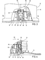
- FIGS. 3 and 4 show the temperature limit switch 12 in its installed position. It is located in a recess formed by the end face 17 and axial and radial intermediate walls 18,19 switch chamber 20.
- the open outer side 21 of the switch chamber 20 flanked tangentially the hub inner wall 16 of the K portable drum 6.
- a fixed contact 26 or a movable spring contact arm 27 can be electrically connected via two parallel connecting lugs 24, 25 which pass through the inner narrow side 23 of the switch bed 22.
- the switch has a bimetallic spring washer 28, which is attached to the spring contact arm 27 as seen from the open side of the switch bed 22.
- the approximately parallel arrangement of these components results in an elongated, flat design.
- the longitudinal direction 35 of the temperature limit switch 12 runs parallel to the hub axis. It has its smallest dimensions in the radial direction.
- the bimetallic spring washer 28 must be able to detect the temperature in the winding space 15 as quickly as possible. Therefore, the temperature limit switch 12 is arranged so that the bimetallic spring washer 28 is close and approximately parallel to the surface of the hub inner wall 16 of the cable drum 6. The thermal radiation 34 and convection emanating from the inner wall 16 of the hub can thus act well on the bimetallic spring disk 28.
Landscapes
- Storing, Repeated Paying-Out, And Re-Storing Of Elongated Articles (AREA)
- Discharging, Photosensitive Material Shape In Electrophotography (AREA)
- Thermally Actuated Switches (AREA)
- Storage Of Web-Like Or Filamentary Materials (AREA)
- Compounds Of Unknown Constitution (AREA)
- Investigating Or Analysing Biological Materials (AREA)
- Control Of Temperature (AREA)
Priority Applications (1)
| Application Number | Priority Date | Filing Date | Title |
|---|---|---|---|
| AT85114784T ATE36432T1 (de) | 1984-12-15 | 1985-11-21 | Leitungsroller mit temperaturbegrenzungsschalter. |
Applications Claiming Priority (2)
| Application Number | Priority Date | Filing Date | Title |
|---|---|---|---|
| DE8436765U DE8436765U1 (de) | 1984-12-15 | 1984-12-15 | Leitungsroller mit Temperaturbegrenzungsschalter |
| DE8436765U | 1984-12-15 |
Publications (2)
| Publication Number | Publication Date |
|---|---|
| EP0185932A1 true EP0185932A1 (fr) | 1986-07-02 |
| EP0185932B1 EP0185932B1 (fr) | 1988-08-10 |
Family
ID=6773800
Family Applications (1)
| Application Number | Title | Priority Date | Filing Date |
|---|---|---|---|
| EP85114784A Expired EP0185932B1 (fr) | 1984-12-15 | 1985-11-21 | Enrouleur de câble à interrupteur de limitation de température |
Country Status (5)
| Country | Link |
|---|---|
| EP (1) | EP0185932B1 (fr) |
| AT (1) | ATE36432T1 (fr) |
| DE (2) | DE8436765U1 (fr) |
| FI (1) | FI81464C (fr) |
| NO (1) | NO166470C (fr) |
Cited By (3)
| Publication number | Priority date | Publication date | Assignee | Title |
|---|---|---|---|---|
| EP1361636A1 (fr) * | 2002-05-10 | 2003-11-12 | Hugo Brennenstuhl GmbH & Co. KG | Disjoncteur de protection pour tambour à cable |
| USD584937S1 (en) | 2007-01-31 | 2009-01-20 | Alert Safety Lite Products Co., Inc. | Cord reel |
| USD604244S1 (en) | 2007-10-10 | 2009-11-17 | Alert Stamping & Manufacturing Co., Inc. | Cord reel |
Families Citing this family (7)
| Publication number | Priority date | Publication date | Assignee | Title |
|---|---|---|---|---|
| DE8436765U1 (de) * | 1984-12-15 | 1985-03-28 | Popp + Co Gmbh, 8582 Bad Berneck | Leitungsroller mit Temperaturbegrenzungsschalter |
| GB8518555D0 (en) | 1985-07-23 | 1985-08-29 | Yang Tai Her | Charging wire for car use |
| DE19826926B4 (de) * | 1998-06-17 | 2004-02-12 | BSH Bosch und Siemens Hausgeräte GmbH | Raumfest angeordnete Kabelaufwickelvorrichtung |
| DE20203277U1 (de) * | 2002-02-28 | 2002-05-08 | Uni-Elektra GmbH, 75395 Ostelsheim | Kabeltrommel mit Thermoüberlastschutz |
| WO2010023527A2 (fr) * | 2008-08-26 | 2010-03-04 | Panasonic Electric Works Co., Ltd. | Ensemble cordon de charge de véhicule électrique |
| DE102016221099A1 (de) * | 2016-10-26 | 2018-04-26 | Schill GmbH & Co. KG | Kabeltrommel |
| DE102018122065A1 (de) * | 2018-09-11 | 2020-03-12 | HEDI GmbH Elektro- und Gerätebau | Kabeltrommel mit schräg gestellter Trommelachse |
Citations (5)
| Publication number | Priority date | Publication date | Assignee | Title |
|---|---|---|---|---|
| DE1590291A1 (de) * | 1966-04-04 | 1970-07-30 | Seger & Angermeyer Desco Werk | Wickelhaspel mit UEbertemperaturschutz fuer elektrische Leitungen |
| DE2752429A1 (de) * | 1977-11-24 | 1979-05-31 | Popp & Co | Kabeltrommel |
| FR2455348A1 (fr) * | 1979-04-25 | 1980-11-21 | Hofsass P | Corps de bobine electrique a commutateur de protection contre la chaleur |
| DE3331847A1 (de) * | 1983-09-03 | 1985-03-21 | Inter Control Hermann Köhler Elektrik GmbH & Co KG, 8500 Nürnberg | Kabeltrommel |
| DE8436765U1 (de) * | 1984-12-15 | 1985-03-28 | Popp + Co Gmbh, 8582 Bad Berneck | Leitungsroller mit Temperaturbegrenzungsschalter |
-
1984
- 1984-12-15 DE DE8436765U patent/DE8436765U1/de not_active Expired
-
1985
- 1985-11-21 AT AT85114784T patent/ATE36432T1/de not_active IP Right Cessation
- 1985-11-21 EP EP85114784A patent/EP0185932B1/fr not_active Expired
- 1985-11-21 DE DE8585114784T patent/DE3564359D1/de not_active Expired
- 1985-12-05 FI FI854828A patent/FI81464C/fi not_active IP Right Cessation
- 1985-12-11 NO NO854961A patent/NO166470C/no not_active IP Right Cessation
Patent Citations (5)
| Publication number | Priority date | Publication date | Assignee | Title |
|---|---|---|---|---|
| DE1590291A1 (de) * | 1966-04-04 | 1970-07-30 | Seger & Angermeyer Desco Werk | Wickelhaspel mit UEbertemperaturschutz fuer elektrische Leitungen |
| DE2752429A1 (de) * | 1977-11-24 | 1979-05-31 | Popp & Co | Kabeltrommel |
| FR2455348A1 (fr) * | 1979-04-25 | 1980-11-21 | Hofsass P | Corps de bobine electrique a commutateur de protection contre la chaleur |
| DE3331847A1 (de) * | 1983-09-03 | 1985-03-21 | Inter Control Hermann Köhler Elektrik GmbH & Co KG, 8500 Nürnberg | Kabeltrommel |
| DE8436765U1 (de) * | 1984-12-15 | 1985-03-28 | Popp + Co Gmbh, 8582 Bad Berneck | Leitungsroller mit Temperaturbegrenzungsschalter |
Cited By (3)
| Publication number | Priority date | Publication date | Assignee | Title |
|---|---|---|---|---|
| EP1361636A1 (fr) * | 2002-05-10 | 2003-11-12 | Hugo Brennenstuhl GmbH & Co. KG | Disjoncteur de protection pour tambour à cable |
| USD584937S1 (en) | 2007-01-31 | 2009-01-20 | Alert Safety Lite Products Co., Inc. | Cord reel |
| USD604244S1 (en) | 2007-10-10 | 2009-11-17 | Alert Stamping & Manufacturing Co., Inc. | Cord reel |
Also Published As
| Publication number | Publication date |
|---|---|
| FI854828L (fi) | 1986-06-16 |
| ATE36432T1 (de) | 1988-08-15 |
| DE8436765U1 (de) | 1985-03-28 |
| NO166470C (no) | 1991-07-24 |
| NO854961L (no) | 1986-06-16 |
| DE3564359D1 (en) | 1988-09-15 |
| NO166470B (no) | 1991-04-15 |
| EP0185932B1 (fr) | 1988-08-10 |
| FI854828A0 (fi) | 1985-12-05 |
| FI81464C (fi) | 1990-10-10 |
| FI81464B (fi) | 1990-06-29 |
Similar Documents
| Publication | Publication Date | Title |
|---|---|---|
| EP0141923B1 (fr) | Limiteur de température pour plaques de cuisson en vitro-céramique | |
| EP0279368B1 (fr) | Limiteur de température | |
| EP0185932B1 (fr) | Enrouleur de câble à interrupteur de limitation de température | |
| DE19627840A1 (de) | Verbindung | |
| EP0203449A1 (fr) | Unité de chauffage pour cuisinière électrique | |
| DE19700722A1 (de) | Thermostatisches Ventil | |
| DE102004015313B3 (de) | Drehlager mit Stromdurchführung | |
| EP0584587B1 (fr) | Interrupteur à fusible avec coupure de la tension aux deux cÔtés | |
| DE3604021A1 (de) | Thermostat | |
| DE2748667C2 (de) | Endlos drehbare, ein- oder mehrpolige elektrische Leitungskupplung | |
| EP0307629A1 (fr) | Plaque de cuisson électrique | |
| EP0735614B1 (fr) | Douille de contact à vis | |
| DE19704575C1 (de) | Schaltgerät | |
| DE1958970A1 (de) | Hitze- bzw. Feuer-Anzeigeeinrichtung | |
| EP0254157A2 (fr) | Accouplement rotatif pour un appareil électrique | |
| DE4138814C2 (de) | Temperatur-Schaltgerät | |
| EP1232544B1 (fr) | Ensemble balais pour une machine electrique | |
| DE3340658A1 (de) | Gehaeuse fuer elektrische schaltelemente | |
| DE1632626C (de) | Elektrischer Zigarrenanzünder | |
| EP2649626B1 (fr) | Arrangement de commutation | |
| EP0043406B1 (fr) | Elément interrupteur de protection pour être ajouté à un appareil interrupteur construit comme interrupteur rotatif | |
| DE3448112C2 (en) | Portable cable drum | |
| DE4134171C2 (de) | Elektrischer Zigarrenanzünder mit Überhitzungsschutz | |
| DE1915816C (de) | Überstromselbstschalter | |
| DE3619243A1 (de) | Temperaturregler |
Legal Events
| Date | Code | Title | Description |
|---|---|---|---|
| PUAI | Public reference made under article 153(3) epc to a published international application that has entered the european phase |
Free format text: ORIGINAL CODE: 0009012 |
|
| AK | Designated contracting states |
Kind code of ref document: A1 Designated state(s): AT BE DE FR NL SE |
|
| EL | Fr: translation of claims filed | ||
| TCNL | Nl: translation of patent claims filed | ||
| 17P | Request for examination filed |
Effective date: 19860804 |
|
| 17Q | First examination report despatched |
Effective date: 19880119 |
|
| GRAA | (expected) grant |
Free format text: ORIGINAL CODE: 0009210 |
|
| AK | Designated contracting states |
Kind code of ref document: B1 Designated state(s): AT BE DE FR NL SE |
|
| REF | Corresponds to: |
Ref document number: 36432 Country of ref document: AT Date of ref document: 19880815 Kind code of ref document: T |
|
| REF | Corresponds to: |
Ref document number: 3564359 Country of ref document: DE Date of ref document: 19880915 |
|
| ET | Fr: translation filed | ||
| PLBE | No opposition filed within time limit |
Free format text: ORIGINAL CODE: 0009261 |
|
| STAA | Information on the status of an ep patent application or granted ep patent |
Free format text: STATUS: NO OPPOSITION FILED WITHIN TIME LIMIT |
|
| 26N | No opposition filed | ||
| EAL | Se: european patent in force in sweden |
Ref document number: 85114784.3 |
|
| PGFP | Annual fee paid to national office [announced via postgrant information from national office to epo] |
Ref country code: FR Payment date: 19991116 Year of fee payment: 15 |
|
| PGFP | Annual fee paid to national office [announced via postgrant information from national office to epo] |
Ref country code: SE Payment date: 19991119 Year of fee payment: 15 Ref country code: AT Payment date: 19991119 Year of fee payment: 15 |
|
| PGFP | Annual fee paid to national office [announced via postgrant information from national office to epo] |
Ref country code: NL Payment date: 19991122 Year of fee payment: 15 |
|
| PGFP | Annual fee paid to national office [announced via postgrant information from national office to epo] |
Ref country code: BE Payment date: 19991123 Year of fee payment: 15 |
|
| PGFP | Annual fee paid to national office [announced via postgrant information from national office to epo] |
Ref country code: DE Payment date: 19991221 Year of fee payment: 15 |
|
| PG25 | Lapsed in a contracting state [announced via postgrant information from national office to epo] |
Ref country code: AT Free format text: LAPSE BECAUSE OF NON-PAYMENT OF DUE FEES Effective date: 20001121 |
|
| PG25 | Lapsed in a contracting state [announced via postgrant information from national office to epo] |
Ref country code: SE Free format text: THE PATENT HAS BEEN ANNULLED BY A DECISION OF A NATIONAL AUTHORITY Effective date: 20001129 |
|
| PG25 | Lapsed in a contracting state [announced via postgrant information from national office to epo] |
Ref country code: BE Free format text: LAPSE BECAUSE OF NON-PAYMENT OF DUE FEES Effective date: 20001130 |
|
| BERE | Be: lapsed |
Owner name: POPP & CO. G.M.B.H. Effective date: 20001130 |
|
| PG25 | Lapsed in a contracting state [announced via postgrant information from national office to epo] |
Ref country code: NL Free format text: LAPSE BECAUSE OF NON-PAYMENT OF DUE FEES Effective date: 20010601 |
|
| EUG | Se: european patent has lapsed |
Ref document number: 85114784.3 |
|
| PG25 | Lapsed in a contracting state [announced via postgrant information from national office to epo] |
Ref country code: FR Free format text: LAPSE BECAUSE OF NON-PAYMENT OF DUE FEES Effective date: 20010731 |
|
| NLV4 | Nl: lapsed or anulled due to non-payment of the annual fee |
Effective date: 20010601 |
|
| PG25 | Lapsed in a contracting state [announced via postgrant information from national office to epo] |
Ref country code: DE Free format text: LAPSE BECAUSE OF NON-PAYMENT OF DUE FEES Effective date: 20010801 |
|
| REG | Reference to a national code |
Ref country code: FR Ref legal event code: ST |