EP0185949A2 - Vorrichtung zum Messen der Grenzwellenlänge von Monomodenglasfasern - Google Patents
Vorrichtung zum Messen der Grenzwellenlänge von Monomodenglasfasern Download PDFInfo
- Publication number
- EP0185949A2 EP0185949A2 EP85114985A EP85114985A EP0185949A2 EP 0185949 A2 EP0185949 A2 EP 0185949A2 EP 85114985 A EP85114985 A EP 85114985A EP 85114985 A EP85114985 A EP 85114985A EP 0185949 A2 EP0185949 A2 EP 0185949A2
- Authority
- EP
- European Patent Office
- Prior art keywords
- fiber
- curvature
- bend
- radius
- imparting
- Prior art date
- Legal status (The legal status is an assumption and is not a legal conclusion. Google has not performed a legal analysis and makes no representation as to the accuracy of the status listed.)
- Granted
Links
- 239000013307 optical fiber Substances 0.000 title claims abstract description 43
- 239000000835 fiber Substances 0.000 claims abstract description 267
- 238000005452 bending Methods 0.000 claims abstract description 32
- 230000003287 optical effect Effects 0.000 claims description 27
- 238000012360 testing method Methods 0.000 abstract description 57
- 238000005259 measurement Methods 0.000 description 40
- 238000000034 method Methods 0.000 description 20
- 230000008859 change Effects 0.000 description 12
- 239000002390 adhesive tape Substances 0.000 description 7
- 230000008878 coupling Effects 0.000 description 6
- 238000010168 coupling process Methods 0.000 description 6
- 238000005859 coupling reaction Methods 0.000 description 6
- 230000000717 retained effect Effects 0.000 description 6
- 230000002411 adverse Effects 0.000 description 5
- 238000004364 calculation method Methods 0.000 description 4
- 238000010586 diagram Methods 0.000 description 4
- 238000004804 winding Methods 0.000 description 4
- 230000008901 benefit Effects 0.000 description 2
- 238000007796 conventional method Methods 0.000 description 2
- 238000006073 displacement reaction Methods 0.000 description 2
- 230000000694 effects Effects 0.000 description 2
- 238000012986 modification Methods 0.000 description 2
- 230000004048 modification Effects 0.000 description 2
- PNUGGYXQDMFFMR-UHFFFAOYSA-N C[O]1CCCC1 Chemical compound C[O]1CCCC1 PNUGGYXQDMFFMR-UHFFFAOYSA-N 0.000 description 1
- 230000009471 action Effects 0.000 description 1
- 230000005540 biological transmission Effects 0.000 description 1
- 238000004891 communication Methods 0.000 description 1
- 230000000593 degrading effect Effects 0.000 description 1
- 238000001514 detection method Methods 0.000 description 1
- 238000011161 development Methods 0.000 description 1
- 238000005516 engineering process Methods 0.000 description 1
- 230000005284 excitation Effects 0.000 description 1
- 238000007689 inspection Methods 0.000 description 1
- 238000012423 maintenance Methods 0.000 description 1
- 238000004519 manufacturing process Methods 0.000 description 1
- 230000007246 mechanism Effects 0.000 description 1
- 230000000644 propagated effect Effects 0.000 description 1
- 230000001902 propagating effect Effects 0.000 description 1
- 239000004065 semiconductor Substances 0.000 description 1
Images



Classifications
-
- G—PHYSICS
- G01—MEASURING; TESTING
- G01N—INVESTIGATING OR ANALYSING MATERIALS BY DETERMINING THEIR CHEMICAL OR PHYSICAL PROPERTIES
- G01N21/00—Investigating or analysing materials by the use of optical means, i.e. using sub-millimetre waves, infrared, visible or ultraviolet light
- G01N21/84—Systems specially adapted for particular applications
-
- G—PHYSICS
- G01—MEASURING; TESTING
- G01M—TESTING STATIC OR DYNAMIC BALANCE OF MACHINES OR STRUCTURES; TESTING OF STRUCTURES OR APPARATUS, NOT OTHERWISE PROVIDED FOR
- G01M11/00—Testing of optical apparatus; Testing structures by optical methods not otherwise provided for
- G01M11/08—Testing mechanical properties
- G01M11/088—Testing mechanical properties of optical fibres; Mechanical features associated with the optical testing of optical fibres
-
- G—PHYSICS
- G01—MEASURING; TESTING
- G01N—INVESTIGATING OR ANALYSING MATERIALS BY DETERMINING THEIR CHEMICAL OR PHYSICAL PROPERTIES
- G01N11/00—Investigating flow properties of materials, e.g. viscosity, plasticity; Analysing materials by determining flow properties
Definitions
- the invention relates to an apparatus capable of precisely measuring the cut-off wavelength of a single-mode optical fiber in an easy and labor-saving manner.
- the primary object, therefore, of the present invention is to provide an apparatus for measuring the cut-off wavelength of a single-mode optical fiber that is free from the problem of torsion development and is capable of imparting a bend to the fiber in a stable attitude during measurement and which ensures simple and continuous realization and maintenance of both the "state where no bend is given to the fiber" and the "state where a bend is given to the fiber", once the fiber under test is set in the apparatus, thereby assuring high precision of measurement and enabling improved and efficient operations of measurements.
- the invention provides an apparatus for measuring the cut-off wavelength of a single-mode optical fiber that includes a light source that is designed to be connected to one end of the single-mode fiber to be tested and which is capable of emitting light having varying wavelengths and an optical detector connected to the other end of the fiber.
- the invention measures the cut-off wavelength of the fiber by comparing an optical output obtained at the other end of the optical fiber when a bend having a larger radius-of-curvature is given to the fiber with an optical output obtained at the other end of the fiber when a bend of a smaller radius-of-curvature is given to the fiber.
- the apparatus according to the invention further includes two fiber bending units that provide the fiber, under test between the light source and the optical detector, with arched bends having different radii of curvature.
- the first fiber bending unit provides the bend with the larger radius-of-curvature and includes two larger radius-. of-curvature bend imparting members having arched curved surfaces with the same radius-of-curvature, the members being arranged so that they have two common parallel tangents and that the tangent to a bend at the point where it starts to be applied to the fiber by one of the members is collinear with the tangent to a bend at the point where it ⁇ starts to be applied to the fiber by the other member.
- One of the larger radius-of-curvature bend imparting members is fixed whereas the other member is movable in a direction parallel to the tangents.
- the other larger radius-of-curvature bend imparting member is provided with a tension imparting unit that applies a biasing force in a direction that is parallel to the tangents and which departs from the one larger radius-of-curvature bend imparting member.
- the two larger radius-of-curvature bend imparting members are constructed so that they will bend the fiber under test into a taut loop.
- the minimum radius-of-curvature applied to the fiber under test is equal to the radius of the arched curved surface, and the length of that portion of the fiber which is bent with the radius of the arched curved surface is equal to the circumference of a single circle having the radius of the arched curved surface.
- the second fiber bending unit provides the bend with the smaller radius-of-curvature and is constructed so that it will press an arched curved surface, having the small radius-of-curvature, against the fiber under test, thereby providing the necessary amount of bend.
- the fiber under test is bent into a taut loop between the light source and the optical detector.
- the radius-of-curvature of the looped bend is equal to the radius of the arched curved surface formed by each of the larger radius-of-curvature bend imparting members and the length of that portion of the fiber that is bent into a loop with the radius of the arched curved surface is equal to the circumference of a single circle having the radius of the arched curved surface.
- the fiber under test is subjected to the same amount of bend as would be applied when it is wound around a cylinder having a curvature equal to that of the looped bend.
- the fiber having the looped bend is fixed at both ends, but since the tension imparting unit enables the fiber under test to be held taut by a suitably slight degree around the larger radius-of-curvature bend imparting members, any torsion that has developed in the fiber will not be transmitted to-either end of the fiber in a sufficient amount to cause an unwanted change in the state of coupling of the fiber with the light source or optical detector.
- the movable larger radius-of-curvature bend imparting member of the first fiber bending unit is moved by the tension imparting unit in a direction parallel to the tangents of the two larger radius-of-curvature bend imparting members, whereby the fiber under test is held taut by a suitably slight degree.
- the fiber under test can be maintained in a very stable state during measurement without securing the fiber to the bend imparting members with, for example, adhesive tape in order to counteract the restoring force of the fiber.
- the entire-absence of the need for securing the fiber with adhesive tape or other fastener will considerably simplify the setting up operation of the apparatus and avoid the occurrence of any bend that may cause adverse effects on the intended measurement.
- the fiber under test is wound around the pair of larger radius-of-curvature bend imparting -members, so the span of the fiber under test can be limited to a relatively small range.
- the second fiber bending unit is then operated to impart to the fiber the bend with the smaller radius-of-curvature, thereby realizing the "state where a bend is given to the fiber". This provides a very simple shift from the "state where no bend is given to the fiber” to the "state where a bend is given to the fiber", and power outputs from the two states can be measured continuously.
- the second fiber bending unit merely presses an arched curved surface with the smaller radius-of-curvature against the fiber and will not cause any torsion in the latter. While it is in operation, the second fiber bending unit will pull the fiber under test but at the same time, a corresponding amount of fiber is delivered by the movable larger radius-of-curvature bend imparting member of the first fiber bending unit which will be displaced toward the fixed, other larger radius-of-curvature bend imparting member so as to counteract the the tension applied by the tension imparting unit. As a result, no excessive force will act on the fiber under test and the latter is continuously held taut by a suitably slight degree.
- FIGURES 1 and 2 are line diagrams showing schematically one embodiment of the apparatus of the present invention for measuring the cut-off wavelength of a single-mode optical fiber.
- FIGURE 1 shows the state where a bend with the larger radius-of-curvature is being given to the fiber under test
- FIGURE 2 shows the state where a bend with the smaller radius-of-curvature is given to the fiber.
- the apparatus shown in FIGURES 1 and 2 includes control/calculation unit 10, light source 12 that is capable of issuing light at varying wavelengths under the control of unit 10, and optical detector 14 whose output is connected to unit 10.
- the light source 12 may be composed of a semiconductor laser capable of emitting light having varying wavelengths.
- source 12 may be composed of a white light source and a spectroscope, the latter being controlled by unit 10.
- An optical fiber 16 connected to light source 12 is retained by holder 18 while an optical fiber 20 extending to the detector 14 is retained by holder 22.
- the fiber holders 18 and 22 are respectively disposed in a face-to-face relation with holders 24 and 26 for retaining the optical fiber to be tested.
- the holders 24 and 26 are designed to grip fiber 28 under test by a sufficient strength to prevent fiber 28 from slipping out of the holders even if some amount of tensile force is exerted on the fiber.
- the positions of holders 24 and 26 may be finely adjusted in both x- and y-directions that intersect with each other at right angles in directions perpendicular to the optical axis of fiber 28, as well as in the z-direction which is parallel to that optical axis.
- the first fiber bending unit that will provide a bend having the larger radius-of-curvature to fiber 28, which is retained at the two ends by the holders 24 and 26, and the second fiber bending unit that will provide a bend having the. smaller radius-of-curvature to fiber 28 are disposed between the holders 24 and 26.
- the first fiber bending unit (used to provide the larger radius-of-curvature to fiber 28) has a pair of larger radius-of-curvature bend imparting members each having a curved surface with a radius-of-curvature of, for example, 280 mm.
- One of the two larger radius-of-curvature bend imparting members is crescent member 30 and the other member. is large roller 32.
- the crescent member 30 and large roller 32 have two common tangents which are parallel to each other and one of the tangents lies in an extension of that part of optical fiber 28 which is retained in holders 24 and 26.
- This arrangement prevents optical fiber 28 from bending either at the boundary between that part of the fiber under test which is retained in holder 24 and portion 28A of the fiber lying between crescent member 30 and holder 24 or at the boundary between that part of the fiber under test which is retained in holder 26 and portion 28B of the fiber lying between large roller 32 and holder 26.
- the portions 28A and 28B of the fiber are collinear with 28C which is one of the two common tangents between crescent member 30 and large roller 32.
- the crescent member 30 which is one of the two members that provide fiber 28 with a bend having the larger radius-of-curvature is held fixed so that it will not be displaced in positon.
- the structure of large roller 32 which is the other member of the first fiber bending unit is not shown in detail in FIGURES 1 or 2, but it is disposed to be movable in directions 34A and 34B that are parallel to poftions 28A, 28B and 28C of the optical fiber under test.
- the large roll 32 is provided with a tension imparting unit that imparts a predetermined amount of tension in the direction of 34A, departing away from the crescent member 30.
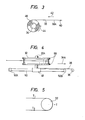
- the tension imparting unit of this type is most readily constructed by a “constant load spring” as shown schematically in FIGURE 3.
- the "constant load spring” is made of leaf spring 38 having one end 38A attached to, for example, the rotational axis of large roller 32 in FIGURE 1 and the other end wound tightly around drum 36 in a coil form.
- the drum 36 is held rotatable at a fixed point distant from large roller 32 in the direction 34A.
- FIGURE 4 is a side view of large roller 32 which is combined with the tension imparting unit comprised of the "constant load spring” described above.
- large roller 32 is supported rotatably on roller shaft 32A which is supported on supporting block 48.
- the block 48 is slidable on slide shaft 50 that has stoppers 50A and 50B on two ends and which extends in the direction 34A shown in FIGURE 1. This arrangement enables large roller 32 to slide in en masse in the direction 34A.
- To support block 48 is fixed one end of the "constant load spring” described above.
- the drum 36 of the "constant load spring” is held on a position distant from large roller 32 in the direction 34A.
- the "constant load spring” pulls large roller 32 in the direction indicated by the arrow 34A so that the fiber under test may be maintained taut by a suitably slight degree that will not adversely affect the intended purpose of measurement. More specifically, large roller 32 is pulled by the “constant load spring” so that a constant amount of tensile force within the range of, say, 10 - 50 g, is exerted on the fiber under test.
- the second fiber bending unit is used to provide optical fiber 28 with a bend having the smaller radius-of-curvature, and this unit has a smaller radius-of-curvature bend imparting member that is composed of three small cylindrical rollers 52, 54 and 56 that have the same small radius-of-curvature of, for example, 60 mm in diameter and which are disposed between holder 24 and crescent member 30.
- the small rollers 52 and 54 are positioned on one side of fiber 28 and are placed in contact therewith so that they will impart no bend to fiber 28.
- the small rollers 52 and 54 are spaced by a distance twice the radius-of-curvature of each roller.
- roller 56 is positioned opposite the small rollers 52 and 54 with respect to fiber 28. As shown in FIGURE 2, roller 56 is capable of pushing fiber 28 and intruding into the space between rollers 52 and 54 up to a point where the centers of the circles defined by the three rollers, 52, 54 and 56 lie in the same straight line or even further beyond said point.
- each of rollers 52 and 54 provides fiber 28 with a bend whose length is equal to one quarter of the circumference of a-circle having the smaller radius-of-curvature while roller 56 provides a bend whose length is equal to one half the circumference of the same circle.
- the fiber under test may be abraded by the surfaces of small rollers 54 and 56 and large roller 32 when small roller 56 intrudes into the space between small rollers 52 and 54.
- small rollers 54 and 56 and large roller 32 are made freely rotatable around their own central axis.
- the smoothly rotatable small rollers 54 and 56 and large roller 32 are effective in applying a constant amount of tension to the fiber under test.
- Tl and T2 develop in the fiber wound around large roller 32. If small rollers 54 and 56 and the large roller 32 are smoothly rotatable, Tl is approximately equal to T2 and a uniform tension is exerted on the entire length of the fiber under test.
- the apparatus described above for measuring the cut-off wavelength of a single-mode optical fiber may be used as follows.
- the measurement of the cut-off wavelength of a single-mode fiber proceeds in a sequence of steps, i.e., the setting up of the fiber to be tested, imparting to the fiber a bend with the larger radius-of-curvature, and imparting to the fiber a bend with the smaller radius-of-curvature. Therefore, the following description is based on the sequence of such steps.
- the experimenter places the small roller 56 in its first position shown in FIGURE 1. He then sets the two ends of optical fiber 28 of a given length, for example 2 m, in respective holders 24 and 26 and winds the middle of fiber 28 around crescent member 30 and large roller 32. As already described, large roller 32 is subjected to a tensile force in the direction 34A and is rendered to be capable of displacement, so fiber 28 is automatically held taut by a suitably slight degree.
- portions 28A, 28B and 28C of fiber-28 are put in the same straight line and both crescent member 30 and large roller 32 provide fiber 28 with a bend whose length is equal to half the circumference of the circle defined by the periphery of each member, thereby producing a bend equivalent to the circumference of one circle formed by the periphery of large roller 32.
- optical detector 14 With fiber 28 adjusted to the state described above, light having a specific wavelength is issued from light source 12 and the transmitted power is detected by optical detector 14.
- the output of detector 14 may be maximized by finely adjusting holders 24 and 26 in the x-, y- or z-directions.
- the distance between one end of fiber 28 and the end of fiber 16 and the distance between the other end of fiber 28 and the end of fiber 20 are each adjusted to the range of several tens of micrometers, and at the same time, the optical axis of fibers 16 and 20 are brought into alignment with the optical axis of fiber 28 under test.
- the light from source 12 is swept over the predetermined range of wavelength, for example, 1.00 - 1.40 ⁇ m, under the control of control/calculation unit 10, and the optical power Pl ( ⁇ ), for each of the wavelengths used, tfiat has been transmitted through fiber 28 and which has been detected by detector 14 is stored in the unit 10.
- the experimenter pushes small roller 56 together with fiber 28 so that the roller is intruded into the space between the other small rollers 52 and 54 up to a point where the centers of the circles defined by the respective small rollers lie in the same straight line or further than this point.
- fiber 28 is provided with a bend equivalent to the circumference of one circle having the smaller radius-of-curvature as shown in FIGURE 2.
- the light from source 12 is swept over the same range of wavelength as used in the measurement of Pl, i.e., 1.00 - 1.40 ⁇ m, under the control of unit 10, and the optical power P2 (X) at each of the wavelengths used that has beep transmitted through fiber 28 and which has been detected by detector 14 is stored in unit 10.
- the wavelength characteristics of the outputs of light that has propagated through fiber 28 in the two different states can be measured.
- the unit 10 then calculates R ( ⁇ ) by formula (1) set forth above, and on the basis of the calculated R (X), the cut-off wavelength of the fiber under test is determined.
- the apparatus of the present invention is performing the sequence of steps described above for measuring the cut-off wavelength of a single-mode optical fiber
- the large roller and the small rollers make smooth rotation and the tension imparting unit generates a constant amount of tension.
- the amount of tension being exerted on the fiber under test is held constant and the fiber is capable of smooth movement.
- the arrangement of the small rollers shown in the illustrated embodiment ensures smooth movement of the fiber under test for two reasons: first, the fiber is not excessively stretched by the bend formed by said small rollers, and second, small rollers 52 and 54 are held in contact with the fiber under test.
- small roller 56 is the only member that moves while a-bend with the smaller radius-of-curvature is imparted to the fiber under test and the minimum amount of movement that must be made by that small roller is approximately equal to its diameter, which is quite advantageous for the purpose of efficient operation of the apparatus.
- the second fiber bending unit that provides a smaller radius-of-curvature bend for the fiber occupies a very small space, which is equivalent to four small rollers.
- large roller 32 which is one of the two larger radius-of-curvature bend imparting members of the first fiber bending unit has a circumference equal to that one complete circle defined by that roller.
- crescent member 30 which is the other member of the first fiber bending unit has a concave edge that defines part of a circle for the specific purpose of expanding the range of movement of large roller 32.
- the first fiber bending unit would be composed of two large rollers 58 and 60, as shown in FIGURE 6. If fiber 28, under test, is held taut around these rollers, the length of the fiber required to span them would be increased;
- the larger radius-of-curvature that can be given to the fiber under test and the length of the latter are generally limited.
- the CCITT recommended in the "Revised Version of Recommendation G652 Characteristics of A Single Mode Fiber Cable” in May 1984 that the larger bend should have a radius-of-curvature of 140 mm and the fiber to be tested should have a length of 2 m.
- the length of the fiber under test is not exactly 2 m and, in actual operations, the fiber length always involves a certain amount of error, which is typically about 0.2 m (in this respect, see Proceedings of SPIE - The International Society for Optical Engineering -, Volume 425, 'Single Mode Optical Fibers', "industrialized measurement system for single mode fibers", D.J. Eccleston and J.M. Dick, pp. 50-5l).
- a crescent member as one of the two larger radius-of-curvature bend imparting members as shown in FIGURES 1 and 2 is advantageous for two reasons: first, a single-mode optical fiber under test with a length of 2 m can be set up on the apparatus for measuring the cut-off wavelength of the fiber; second, two bends with different radii of curvature, one having a radius of 140 mm and the other having a smaller radius, can be imparted to the fiber under test. Therefore, it can be concluded that the arrangement shown above, in FIGURES 1 and 2, of the two larger radius-of-curvature bend imparting members is very effective for accomplishing the objects of the present invention.
- crescent member 30 An embodiment of crescent member 30 is illustrated in FIGURE 7.
- both convex edge 30A and concave edge 30B of crescent member 30 have.an equal radius-of-curvature "r" except that the centers of the imaginary circles formed by the respective edges are offset by a distance "d".
- convex edge 30A provides a bend with the desired larger radius-of-curvature while concave edge 30B will expand the range of movement of large roller 32 which is the other large radius-of-curvature bend imparting member.
- the circumference defined by the combination of the two large radius-of-curvature bend imparting members i.e., crescent member 30 and large roller 32
- the circumference defined by the combination of the two large radius-of-curvature bend imparting members becomes nearly equal to 2 ⁇ r when the two bend portions are brought into close proximity with each other, and as a result, the fiber length that is lost by the bend can be reduced to a minimum level.
- the setup of the unit for imparting a bend with the smaller radius-of-curvature to the fiber under test is hereunder described.
- the unit composed of the small rollers 52, 54 and 56 is positioned between the fiber holder 24 and the crescent member 30.
- the small rollers 52 and 54 as well as the crescent member 30 are fixed, so by disposing the. small roller 54 at a position close to where crescent member 30 starts to impart a bend to fiber 28, under test, a sufficiently large space to permit easy operation is provided in areas around fiber holders 24 and 26.
- the distance between the two points of fiber 28 in contact with small rollers 52 and 54 is 120 mm.
- the length of the fiber 28 between these two points of contact is about 189 mm.
- the necessary range of movement of large roller 32 can be reduced while increasing the range of the fiber length that can be effectively used for measurement purposes.
- large roller 32 may be provided with a flange 66.
- the crescent member 30 may also be provided with a similar flange. These flanges will facilitate the operation of winding fiber 28 around crescent member 30 and large roller 32.
- both fiber holders 24 and 26 are positioned in the same straight line on one . side of the fiber loop formed by crescent member 30 and large roller 32, and this arrangement as combined with the wide space allowed for the areas around holders 24 and 26 will further increase the ease of operations that are involved during the equipment setup and cut-off wavelength measurement. If an air cylinder or other suitable means are used to automate the movement of small roller 56, the only manual job that is left for the experimenter is to set up the fiber to be tested, and the rest of the operations can be automatically performed to further improve the overall efficiency of measurement. If this is realized, one experimenter may be assigned to the operation of two or more apparatuses.
- the larger and smaller radii of curvature are respectively set to 280 mm and 60 mm in the embodiment. illustrated above, but these are not the only values that can be used for the two different radii of curvature.
- the larger radius-of-curvature can be selected from the range of 200 - 400 mm while the smaller radius-of-curvature can be selected from the range of 50 - 100 mm.
- fibers 16 and 20 are respectively connected to fiber 28, under test, by finely adjusting the positions of holders 24 and 26. If the conditions of a specific measurement permit, fibers 16 and 20 may be connected to fiber 28 by butt-joining on simple V-guides.
- FIGURE 8 A further modification to the illustrated embodiment is shown in FIGURE 8 wherein small rollers 52, 54 and 56 are combined with additional small rollers 54A and 56A.
- the fiber under test is provided with a bend equivalent to the circumference of two circles having the radius of each small roller, one quarter of the circumference of one circle being provided by each of small rollers 52 and 54A, and one half the circumference of one circle provided by each of small rollers 54, 56 and 56A.
- the apparatus of the present invention for measuring the cut-off wavelength of a single-mode optical fiber enables the fiber under test to be easily put to the necessary bend states and such states can be stably held with great ease. If it is desired to impart to the fiber a bend having a geometrically : larger radius-of-curvature, the fiber can be provided with a bend equivalent to the circumference of one circle having said radius-of-curvature. If, on the other hand, it is desired to impart a bend having a smaller radius-of-curvature, the fiber can also be provided with a bend whose length is no smaller than the circumference of one circle having said smaller radius-of-curvature.
- shift from the "state where no bend is given to the fiber” to the "state where a bend is given to the fiber” can be realized without introducing any "torsion” or slackening in the fiber under test, and once the fiber is set up in the apparatus, continuous measurement can be accomplished without upsetting the tension applied to the fiber or the attitude it has acquired.
- the fiber under test is held taut by a suitably slight degree during the measurement, so the fiber need not be secured to the bend imparting members with adhesive tape and other suitable fastening means with a view to counteract the restoring force of the fiber, and the fiber can be maintained in a very stable state throughout the procedures of measurement.
- the entire absence of the need for fastening operations such as securing the fiber with adhesive tape will lead to simplified procedures of the intended measurement.
- the fiber under test is wound around a pair of large radius-of-curvature bend imparting members in a loop form, so the range over which the fiber under test will extend can be reduced to a fairly low level, thereby providing ample operational space for areas around both ends of the fiber under test.
Landscapes
- Chemical & Material Sciences (AREA)
- Analytical Chemistry (AREA)
- Physics & Mathematics (AREA)
- General Physics & Mathematics (AREA)
- Health & Medical Sciences (AREA)
- Life Sciences & Earth Sciences (AREA)
- Biochemistry (AREA)
- General Health & Medical Sciences (AREA)
- Immunology (AREA)
- Pathology (AREA)
- Light Guides In General And Applications Therefor (AREA)
- Testing Of Optical Devices Or Fibers (AREA)
- Length Measuring Devices By Optical Means (AREA)
Applications Claiming Priority (2)
| Application Number | Priority Date | Filing Date | Title |
|---|---|---|---|
| JP59249248A JPS61128134A (ja) | 1984-11-26 | 1984-11-26 | 単一モ−ド光フアイバのカツトオフ波長測定装置 |
| JP249248/84 | 1984-11-26 |
Publications (3)
| Publication Number | Publication Date |
|---|---|
| EP0185949A2 true EP0185949A2 (de) | 1986-07-02 |
| EP0185949A3 EP0185949A3 (en) | 1987-04-15 |
| EP0185949B1 EP0185949B1 (de) | 1989-04-26 |
Family
ID=17190127
Family Applications (1)
| Application Number | Title | Priority Date | Filing Date |
|---|---|---|---|
| EP85114985A Expired EP0185949B1 (de) | 1984-11-26 | 1985-11-26 | Vorrichtung zum Messen der Grenzwellenlänge von Monomodenglasfasern |
Country Status (6)
| Country | Link |
|---|---|
| US (1) | US4636070A (de) |
| EP (1) | EP0185949B1 (de) |
| JP (1) | JPS61128134A (de) |
| KR (1) | KR890001534B1 (de) |
| CA (1) | CA1255921A (de) |
| DE (1) | DE3569826D1 (de) |
Cited By (4)
| Publication number | Priority date | Publication date | Assignee | Title |
|---|---|---|---|---|
| EP0274791A1 (de) * | 1986-12-19 | 1988-07-20 | Philips Patentverwaltung GmbH | Verfahren zur Messung der spezifischen krümmungsabhängigen Dämpfungserhöhung eines LWL |
| EP0361962A3 (de) * | 1988-09-30 | 1990-12-27 | BICC Public Limited Company | Optische Faser-Überwachung |
| DE3937586C1 (en) * | 1989-11-11 | 1991-02-14 | Schott Glaswerke, 6500 Mainz, De | Flexible mono or multi mode optical fibre - transmits polychromatic light esp. laser beam at same transversal radiation modes for each wavelength |
| CN106556508A (zh) * | 2017-01-19 | 2017-04-05 | 长飞光纤光缆股份有限公司 | 一种单模光纤的单模态衰减谱的测试方法 |
Families Citing this family (18)
| Publication number | Priority date | Publication date | Assignee | Title |
|---|---|---|---|---|
| JPS61239137A (ja) * | 1985-04-15 | 1986-10-24 | Sumitomo Electric Ind Ltd | 単一モ−ド光フアイバの特性測定装置 |
| US4822135A (en) * | 1987-08-07 | 1989-04-18 | George Seaver | Optical wave guide band edge sensor and method |
| US4902327A (en) * | 1988-04-27 | 1990-02-20 | Raynet Corporation | Monitoring fiber bend loss characteristics during manufacture |
| DE4005360A1 (de) * | 1990-02-16 | 1991-08-22 | Siecor Ges Fuer Lichtwellenlei | Messbank zur grenzwellenlaengenmessung bei optischen fasern |
| US6456370B1 (en) * | 2001-03-29 | 2002-09-24 | Fitel Usa Corp. | Method of measuring bending loss with an optical time domain reflectometer |
| US6393923B1 (en) * | 2001-04-30 | 2002-05-28 | The United States Of America As Represented By The Secretary Of The Army | Dynamic bendloss measuring device |
| JP5237526B2 (ja) * | 2005-09-20 | 2013-07-17 | パナソニック株式会社 | 光導波路の損失測定方法 |
| US7574082B2 (en) * | 2007-03-28 | 2009-08-11 | Verizon Services Organization Inc. | Optical power monitoring with robotically moved macro-bending |
| EP2237010B8 (de) * | 2009-03-30 | 2018-02-14 | Sumitomo Electric Industries, Ltd. | Grenzwellenlängen-Messverfahren und optisches Kommunikationssystem |
| JP5770517B2 (ja) * | 2011-04-07 | 2015-08-26 | 株式会社フジクラ | 光ファイバのカットオフ波長測定方法 |
| DE102011122209A1 (de) * | 2011-12-23 | 2013-06-27 | Carl Zeiss Meditec Ag | Vorrichtung zur Homogenisierung eines Laserstrahlprofils |
| CN102928203B (zh) * | 2012-11-07 | 2016-02-17 | 中国电子科技集团公司第四十一研究所 | 一种保偏光纤截止波长校准装置及其校准方法 |
| CN104458217B (zh) * | 2014-12-31 | 2017-01-11 | 上海电缆研究所 | 一种同步测试光纤衰减系数和截止波长的测试方法 |
| CN106501108A (zh) * | 2016-09-09 | 2017-03-15 | 中国电力科学研究院 | 一种 opgw 单线扭转疲劳试验方法及装置 |
| CN114341609B (zh) * | 2019-09-12 | 2025-02-25 | 株式会社藤仓 | 光纤的测量装置以及对光纤的弯曲施加方法 |
| WO2021110312A1 (en) * | 2019-12-06 | 2021-06-10 | Gpx Medical Ab | A device for smoothing spectral transmission modulations and a method thereof |
| WO2021251473A1 (ja) * | 2020-06-12 | 2021-12-16 | 住友電気工業株式会社 | 曲げ損失測定用の曲げ付与装置、曲げ試験装置 |
| WO2021251474A1 (ja) * | 2020-06-12 | 2021-12-16 | 住友電気工業株式会社 | 光ファイバの曲げ損失測定方法 |
Family Cites Families (2)
| Publication number | Priority date | Publication date | Assignee | Title |
|---|---|---|---|---|
| DE3039088A1 (de) * | 1980-10-16 | 1981-10-29 | Deutsche Bundespost vertreten durch den Präsidenten des Fernmeldetechnischen Zentralamtes, 6100 Darmstadt | Verfahren und anordnung zur untersuchung des uebertragungsverhaltens von lichtwellenleiterkabeln |
| US4468117A (en) * | 1982-02-22 | 1984-08-28 | General Dynamics | Integrated optical fiber testing device |
-
1984
- 1984-11-26 JP JP59249248A patent/JPS61128134A/ja active Granted
-
1985
- 1985-10-07 KR KR1019850007357A patent/KR890001534B1/ko not_active Expired
- 1985-11-13 US US06/797,667 patent/US4636070A/en not_active Expired - Lifetime
- 1985-11-21 CA CA000495940A patent/CA1255921A/en not_active Expired
- 1985-11-26 DE DE8585114985T patent/DE3569826D1/de not_active Expired
- 1985-11-26 EP EP85114985A patent/EP0185949B1/de not_active Expired
Cited By (4)
| Publication number | Priority date | Publication date | Assignee | Title |
|---|---|---|---|---|
| EP0274791A1 (de) * | 1986-12-19 | 1988-07-20 | Philips Patentverwaltung GmbH | Verfahren zur Messung der spezifischen krümmungsabhängigen Dämpfungserhöhung eines LWL |
| EP0361962A3 (de) * | 1988-09-30 | 1990-12-27 | BICC Public Limited Company | Optische Faser-Überwachung |
| DE3937586C1 (en) * | 1989-11-11 | 1991-02-14 | Schott Glaswerke, 6500 Mainz, De | Flexible mono or multi mode optical fibre - transmits polychromatic light esp. laser beam at same transversal radiation modes for each wavelength |
| CN106556508A (zh) * | 2017-01-19 | 2017-04-05 | 长飞光纤光缆股份有限公司 | 一种单模光纤的单模态衰减谱的测试方法 |
Also Published As
| Publication number | Publication date |
|---|---|
| KR890001534B1 (ko) | 1989-05-06 |
| JPS61128134A (ja) | 1986-06-16 |
| EP0185949B1 (de) | 1989-04-26 |
| CA1255921A (en) | 1989-06-20 |
| US4636070A (en) | 1987-01-13 |
| JPH0250413B2 (de) | 1990-11-02 |
| EP0185949A3 (en) | 1987-04-15 |
| KR860004310A (ko) | 1986-06-20 |
| DE3569826D1 (en) | 1989-06-01 |
Similar Documents
| Publication | Publication Date | Title |
|---|---|---|
| US4636070A (en) | Apparatus for measuring the cut-off wavelength of a single-mode optical fiber | |
| US4714343A (en) | Optical fiber characteristic measurement | |
| EP0393878B1 (de) | Beständigkeitsprüfung von optischen Fasern mittels spiralförmiger Biegung | |
| CA2815756C (en) | Optical light source with controlled launch conditions | |
| US5386484A (en) | Optical fiber type polarizer | |
| US5818982A (en) | Fiber optic sensor based upon buckling of a freely suspended length of fiber | |
| US4915468A (en) | Apparatus using two-mode optical waveguide with non-circular core | |
| US4442350A (en) | Fiber optic sensor with enhanced immunity to random environmental perturbations | |
| US4749246A (en) | Optical fiber sensors | |
| US6393923B1 (en) | Dynamic bendloss measuring device | |
| US6754416B1 (en) | Method for tensioning and positioning a fiber optic cable | |
| KR940009539B1 (ko) | 다중 모의 피일위치 만곡부를 도입한 광섬유 시험 방법 및 그 장치 | |
| US6973223B2 (en) | Device for providing polarized light | |
| US4555175A (en) | Measuring compression of cabled optical fibers | |
| EP0249923B1 (de) | Verfahren und Vorrichtung zur Messung der Polarisations-Schwebungslänge in hoch doppelbrechenden Monomode-Lichtleitfasern | |
| JPS61107129A (ja) | 単一モ−ド光フアイバのカツトオフ波長測定装置 | |
| SU1073612A1 (ru) | Установка дл испытани гибких элементов на усталость | |
| JPH06288865A (ja) | 光ファイバ損失測定器 | |
| EP0775914A2 (de) | Optischer Spannungsfühler, Gruppe optischer Teile und Herstellungsverfahren dazu | |
| US5617210A (en) | Method of detecting whether at least one die is centered about a thread held taught between two fixed points | |
| KR19980016696U (ko) | 인장시험기에 부설되는 원통형 홀더 | |
| WO2026013747A1 (ja) | 光ファイバ巻付装置および光ファイバ評価方法 | |
| US6631003B1 (en) | Uncorrelated michelson interferometer | |
| CN118534575A (zh) | 当将反谐振空芯光纤卷绕成线圈时使该光纤的横截面方位角地对准的技术 | |
| Buffin et al. | Excess signal loss in precision-wound optical fiber |
Legal Events
| Date | Code | Title | Description |
|---|---|---|---|
| PUAI | Public reference made under article 153(3) epc to a published international application that has entered the european phase |
Free format text: ORIGINAL CODE: 0009012 |
|
| AK | Designated contracting states |
Kind code of ref document: A2 Designated state(s): DE FR GB |
|
| PUAL | Search report despatched |
Free format text: ORIGINAL CODE: 0009013 |
|
| AK | Designated contracting states |
Kind code of ref document: A3 Designated state(s): DE FR GB |
|
| 17P | Request for examination filed |
Effective date: 19870604 |
|
| 17Q | First examination report despatched |
Effective date: 19880624 |
|
| GRAA | (expected) grant |
Free format text: ORIGINAL CODE: 0009210 |
|
| AK | Designated contracting states |
Kind code of ref document: B1 Designated state(s): DE FR GB |
|
| REF | Corresponds to: |
Ref document number: 3569826 Country of ref document: DE Date of ref document: 19890601 |
|
| ET | Fr: translation filed | ||
| PLBE | No opposition filed within time limit |
Free format text: ORIGINAL CODE: 0009261 |
|
| STAA | Information on the status of an ep patent application or granted ep patent |
Free format text: STATUS: NO OPPOSITION FILED WITHIN TIME LIMIT |
|
| 26N | No opposition filed | ||
| PGFP | Annual fee paid to national office [announced via postgrant information from national office to epo] |
Ref country code: FR Payment date: 19931110 Year of fee payment: 9 |
|
| PGFP | Annual fee paid to national office [announced via postgrant information from national office to epo] |
Ref country code: GB Payment date: 19931116 Year of fee payment: 9 |
|
| PGFP | Annual fee paid to national office [announced via postgrant information from national office to epo] |
Ref country code: DE Payment date: 19931123 Year of fee payment: 9 |
|
| PG25 | Lapsed in a contracting state [announced via postgrant information from national office to epo] |
Ref country code: GB Effective date: 19941126 |
|
| GBPC | Gb: european patent ceased through non-payment of renewal fee |
Effective date: 19941126 |
|
| PG25 | Lapsed in a contracting state [announced via postgrant information from national office to epo] |
Ref country code: FR Effective date: 19950731 |
|
| PG25 | Lapsed in a contracting state [announced via postgrant information from national office to epo] |
Ref country code: DE Effective date: 19950801 |
|
| REG | Reference to a national code |
Ref country code: FR Ref legal event code: ST |