EP0185953A2 - Cylindre de dilatation avec une longueur élastiquement variable - Google Patents
Cylindre de dilatation avec une longueur élastiquement variable Download PDFInfo
- Publication number
- EP0185953A2 EP0185953A2 EP85115045A EP85115045A EP0185953A2 EP 0185953 A2 EP0185953 A2 EP 0185953A2 EP 85115045 A EP85115045 A EP 85115045A EP 85115045 A EP85115045 A EP 85115045A EP 0185953 A2 EP0185953 A2 EP 0185953A2
- Authority
- EP
- European Patent Office
- Prior art keywords
- expansion
- cylinder
- expansion cylinder
- cylinders
- pressure
- Prior art date
- Legal status (The legal status is an assumption and is not a legal conclusion. Google has not performed a legal analysis and makes no representation as to the accuracy of the status listed.)
- Granted
Links
Images


Classifications
-
- B—PERFORMING OPERATIONS; TRANSPORTING
- B23—MACHINE TOOLS; METAL-WORKING NOT OTHERWISE PROVIDED FOR
- B23Q—DETAILS, COMPONENTS, OR ACCESSORIES FOR MACHINE TOOLS, e.g. ARRANGEMENTS FOR COPYING OR CONTROLLING; MACHINE TOOLS IN GENERAL CHARACTERISED BY THE CONSTRUCTION OF PARTICULAR DETAILS OR COMPONENTS; COMBINATIONS OR ASSOCIATIONS OF METAL-WORKING MACHINES, NOT DIRECTED TO A PARTICULAR RESULT
- B23Q1/00—Members which are comprised in the general build-up of a form of machine, particularly relatively large fixed members
- B23Q1/25—Movable or adjustable work or tool supports
- B23Q1/26—Movable or adjustable work or tool supports characterised by constructional features relating to the co-operation of relatively movable members; Means for preventing relative movement of such members
- B23Q1/34—Relative movement obtained by use of deformable elements, e.g. piezoelectric, magnetostrictive, elastic or thermally-dilatable elements
-
- F—MECHANICAL ENGINEERING; LIGHTING; HEATING; WEAPONS; BLASTING
- F15—FLUID-PRESSURE ACTUATORS; HYDRAULICS OR PNEUMATICS IN GENERAL
- F15B—SYSTEMS ACTING BY MEANS OF FLUIDS IN GENERAL; FLUID-PRESSURE ACTUATORS, e.g. SERVOMOTORS; DETAILS OF FLUID-PRESSURE SYSTEMS, NOT OTHERWISE PROVIDED FOR
- F15B15/00—Fluid-actuated devices for displacing a member from one position to another; Gearing associated therewith
- F15B15/08—Characterised by the construction of the motor unit
- F15B15/10—Characterised by the construction of the motor unit the motor being of diaphragm type
Definitions
- the invention relates to expansion cylinders with an elastically variable length with a round cross-section that does not essentially change in its dimensions.
- the invention aims at advantageous and, above all, new fields of application for new forms of further development of the axially elastic expansion cylinder. It is based on the task, in particular, of providing possible uses for energy conversion, for the leak-free conveyance of flowable media, for carrying out two-dimensional or three-dimensional movement sequences, etc.
- strain cylinder of the initially described type wherein the invention is that a Dehnz y-relieving and with further Dehnzylindern BEZW. or other movable separators combined into a functional unit or respectively. and individual expansion cylinders or all expansion cylinders of the functional unit devices. Precautions are functionally assigned, by means of which two- or three-dimensional movements of the free cylinder ends can be carried out during the stretching process.
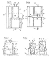
- Fig. 1 two expansion cylinders 1 and 2 of different diameters are nested and fastened with their lower ends to a common base plate 3.
- the space between the two expansion cylinders 1 and 2 is dimensioned so that a set of rings 5 made of round steel can be used as intermediate reinforcement.
- the upper floors or lids 6 and 7 touch.
- the interior 4 has connections 8 and can serve as a pressure accumulator, pulsation damper, etc.
- With axial expansion the wall thickness of both expansion cylinders decreases. While the inner diameter of the inner cylinder 1 increases, that of the outer cylinder (2) remains the same, since there is no internal pressure and, due to the constriction caused by longitudinal expansion, it rests on the reinforcement 5.
- the wall thickness of the inner cylinder 1 must of course have a minimum thickness which results from the properties of the elastomer and the design of the reinforcing elements (rings, winding, material).
- FIG. 2 shows a top view and in section of two concentrically arranged expansion cylinders 1 and 2 which are connected to one another via common end plates 3 and 9.
- the two interior spaces 10 and 11 have supply lines 12 and 13.
- one of the cylinders 1 or 2 expands due to pressure filling, it expands necessarily the other with, so that the arrangement as a pump. can serve as a pressure booster or coaster.
- FIG. 3 also shows a device with two concentric expansion cylinders 1 and 2. If the outer expansion cylinder 2 is pressurized (gas, liquid), it expands and its cover 7 rises, for example, from position a to a '.
- the overpressure in room 11 initially also acts on the expansion cylinder as an external overpressure. If the inner expansion cylinder 1 is now filled with a pressure medium or stretched from b to b 'by a rod 14, this also causes a further expansion of the outer cylinder from a' to a '', transmitted by the medium located therein. Its filling pressure and compressibility determine, in addition to the spring rates of the two expansion cylinders, the overall characteristics of the accumulator. 3, which is thus adjustable in operation.
- Expansion cylinders assigned in pairs to one another can be designed as a pump construction in that both cylinders act as a tandem, in which case an external drive is required, or in that one expansion cylinder can serve as a drive and the other as a pump.
- FIGS. 4 to 6 show some exemplary embodiments.
- two expansion cylinders 1 and 2 fastened on a base plate 3 next to one another with some intermediate space are each connected to a pressure line 15 and a suction line 16, preferably via one-way valves.
- the covers 6 are fastened via joints 19 to a pivot beam 20 mounted in the center. If the beam bearing 19 is raised by the extension length 18 with the aid of the support 17, then both expansion cylinders are stretched by the amount 18 with the same dimensions. biased. 2 x 18 is the total stroke 21 of each of the expansion cylinders, their unstretched length is designated 22.
- the pump is actuated by pivoting movement of the beam 20 about its pivot point 19.
- the two cylinders 1 and 2 do not have to be the same size, but can differ in size and stroke if the rotary actuator is adapted accordingly. - If you swap the pressure and suction line and ensure stroke-dependent control of the valves, the arrangement shown in Fig. 4 can also be used as a pneumatic or hydraulic two-piston engine.
- two unequal expansion accumulators 1 and 2 are arranged one above the other and by a common connecting plate 28 connected with each other.
- the unilaterally elongated floors 3 and 6 are connected to the ends of a cross member 25 so that both expansion cylinders bias one another.
- the preload stroke of cylinder 1 is greater than that of cylinder 2, as indicated by 26 and 27.
- the lower expansion cylinder 2 is alternately filled and emptied with a pressure medium via the feed line 8.
- the permissible stroke corresponds to the preload stroke amount 26 and is also the delivery stroke of the pump cylinder 1.
- FIG. 6 shows a pump of a similar design, in which, however, the two expansion cylinders 1 and 2 are flowed through by the pumped medium, and without reversing direction.
- the mutually facing floors 3 and 6 are connected to each other by a coupling rod 30 and together by a pivot lever 31 which swings about its pivot bearing 19 arranged on the crossmember 25, up and down.
- the lower expansion tank 2 is equipped with a suction port 24 with a check valve and serves as a pump chamber.
- the connecting pipe 29 leading to the upper expansion cylinder 1 is also provided with a check valve and serves as a pressure port.
- the interior of the upper cylinder 1 serves as a compensation space for the medium flowing through it.
- Fig. 7 shows an expansion cylinder construction as a shock absorber or spring element.
- a weakly dimensioned expansion cylinder 1 is arranged above a base plate 34, and a more dimensionally dimensioned expansion cylinder 2 is arranged below it. They are connected to one another through the opening 29.
- Port 8 gives the possibility to pressurize the two expansion cylinders as required.
- the upper expansion cylinder 1 experiences a preload stroke 21, which is available as a spring stroke with respect to the plate 34 for forces K acting from above.
- the elastic spring force is provided by the lower expansion memory 2, back vibrations can be limited by stops 35 for the cover 6 of the expansion memory 1.
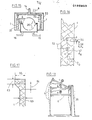
- FIG. 8 shows the combination of a piston pump with an expansion cylinder and a membrane to form a completely leak-free metering pump.
- the membrane 36 is firmly connected to the rod 14 of the piston 37 and separates two liquids at the same pressure from one another, on the one hand via the exchange line 32 or Pumped medium penetrated via the annular gap between piston 37 and cylinder 39, on the other hand a transfer liquid filled in via connection 8, which is inert for the elastomer.
- Figures 9 and 10 show two pressure accumulators, preferably for pulsation damping.
- the storage function is performed by a stretching cylinder 1.
- a pressure-operated membrane 36 serves as a separating element in FIG. A and B resp.
- a 'and B' give the empty resp. filled position d of the pressure accumulator.
- a bellows, folding cylinder or shaft cylinder 38 is provided instead of the membrane.
- the cover of the bellows can be firmly connected to the cover 6 of the expansion cylinder 1. If, however, the bellows are to be operated without pressure, the annular space 11 between bellows 38 and expansion cylinder 1 is to be filled with a transmission fluid, as shown.
- the stroke 26 of the bellows is larger than the stroke 27 of the expansion cylinder 1 because of its smaller cross section.
- Fig. 11 shows a pump in which a piston 37 is rigidly connected to the cover 6 of an expansion cylinder 1 of larger diameter via coupling rods 30.
- the cylinder-piston unit 37, 39 is operated in that the interior 4 of the expansion cylinder 1 via port 8 by pressure air is expanded and expands again after pressure relief.
- the piston can also serve hydraulically as a drive and the expansion cylinder can be used as a pump chamber.
- the pressure transmission ratio in the respective operating mode results from the ratio of the cross sections of piston 37 and expansion cylinder 1.
- the pump arrangement according to FIG. 12 contains the features of FIGS. 6 and 8 according to the invention. It represents a hermetic piston pump through which there is no reversal of direction. In order to carry out the pump stroke 21, the connecting plate 28 has to be moved alternately by an external drive.
- FIGS. 13 and 14 show examples of a pneumatic or hydraulic working cylinder.
- a piston 37 runs in a cylinder 39 provided with two connections 8, 24.
- the piston rod 59 is guided through a sleeve 61 by means of a non-sealing slide bearing.
- a Dehnz y linder small cross-section 60 provides sealing to the outside in that it is attached to the piston rod 59 on the one hand, and to the bottom of the cylinder 39 on the piston rod side on the other hand.
- 13 shows the sealing cylinder 60, which moves like the piston 37, in the most extended position.
- the 14 also has two pressure chambers with the connections 8, 24 for the pressure-dependent assignment of the piston rod 59.
- the piston 37 instead of the piston 37, however, it has an expansion cylinder 66 which has a much larger diameter than the sealing expansion cylinder 60 and in which rigid cylinder 39 is housed.
- One bottom of the drive cylinder 66 coincides with the bottom 3 of the cylinder 39 facing away from the piston rod, the other bottom, penetrated centrally by the piston rod 59, is firmly connected to the bottom.
- the cylinder 39 has a plain bearing 51 on one floor and the opposite one Bottom a guide sleeve 62 for the piston rod 59.
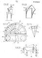
- the expansion cylinder 1 which is biased by a coil spring 33, is driven by pulsating excess pressure in the container 50 provided with the feed line 8.
- the resulting pumping action in the interior 4 of the expansion cylinder 1 is transmitted to the delivery medium through the membrane 36, which in turn is operated without pressure.
- the expansion cylinder 1 can also be driven mechanically via the rod 14.
- the biasing spring 33 and the outer housing 50 are omitted for simplification.
- the arrangement shown in FIG. 15 can also be operated as a hydraulic motor.
- the expansion cylinder 1 by a rhythmically changing pressure of a via connections 15, 16 zu- resp. removed hydraulic fluid moves back and forth and transmits its axial movements to the lifting rod 14, which can drive a crank.
- the membrane 36 the object of providing a contact of the elastomer of the Dehnz y Linders 1 with the pressure fluid. e.g. To prevent hydraulic oil.
- FIG. 16 represents a wall section of an expansion cylinder 1.
- the thickness of the unloaded rubber wall is t G
- the diameter of the reinforcement elements d R (57) measured in the radial direction, while its axially measured diameter is d A (56).
- the axial distance between the reinforcing elements 52 is s o (58).
- the ratio t G : d R should advantageously be greater than 2 to 3
- the ratio s o : d A should be greater than 1 and preferably greater than 2.
- arrangements are preferred in which t G : d R xs o : d A is greater than 3.
- Figure 17 gives suggested dimensions for the connection the cylinder body ends with the end covers made of metal or plastic of appropriate strength.
- 53 is the wall thickness of the expansion cylinder 1.
- dimension 54 is approximately the same as 53, and dimension 55 is approximately twice as large. If the flange is formed entirely of elastomer and are held by a clamping ring, so it is safe for a hme n up the stretching forces advantageous if the dimension 63 also is approximately equal to 53. If we use instead of or in addition to a clamping Vulcanization connection, for example with a ring of width 55, the thickness 63 may also be smaller than the dimension 53 according to the static requirements. Incidentally, it may be expedient to point a flange outwards and the opposite flange in the interior of the expansion hose.
- FIGS. 18 to 23 show precautions for executing multi-dimensional movements of expansion cylinders.
- Fig. 18 shows an expansion cylinder 1 with cover 6, on which a rod is attached with a connecting eye.
- a stop 35 is attached in such a way that after an initially straight initial stroke of the expansion cylinder 1 it comes into contact with its cover 6 and thereby prevents further expansion on this side of the expansion cylinder.
- the cover 6 executes a lateral inclination.
- the different positions of the connecting eye are marked by a, b and c.
- the expansion cylinder 1 is connected to the guide rail or curve via guide pieces 41 such that the free end of the expansion cylinder follows the guide rail 40 in its movements.
- FIG. 20 shows an axially elastic expansion cylinder which, when the filling pressure is increased, simultaneously expands and curves laterally. This is achieved in that a tensioning element 42 is laid between the surface of the expansion cylinder 1 and its outer reinforcement 52, which the connects both bottoms of the expansion cylinder 1 'to one another.
- the sequence of movements of the cylinder end can be done by placing the tensioning element. a combination of clamping aids changed or changed in wide areas. to be influenced.
- Fig. 21 shows possible embodiments for achieving a circular path of the free cylinder end. This creates hermetic, self-resetting rotary actuators for pneumatics and hydraulics.
- the expansion body 47 can be fastened on a base plate 64, in which a pivot point or pivot bearing 45 is provided at a distance from the center 65 of the base of the expansion cylinder.
- a pivot point or pivot bearing 45 is provided at a distance from the center 65 of the base of the expansion cylinder.
- One or more of these go with the expansion body or. with the external reinforcement pivotable spokes 46 connected to the cylinder end, which guide the expansion body as it moves.
- Another possibility is to attach guide rollers or sliding elements 44 to the expansion cylinder which are guided by guide rails or sliding surfaces 43.
- the guide of the free end and all portions of the Dehnz y Linders can also be effected by ' Komoination of the devices described above.
- care must also be taken to ensure that the pivoting cylinder cannot move out of the pivoting plane under the action of counterforces on its movable end.
- a spatial manipulator shown in FIG. 23 Multiple Strain cylinder 1 rigidly engage possibly at the corners of Manipulierrahmens 48, 4 9 and bring them by different degrees of filling of the individual cylinders in the desired positions.
Landscapes
- Engineering & Computer Science (AREA)
- Mechanical Engineering (AREA)
- Physics & Mathematics (AREA)
- Fluid Mechanics (AREA)
- General Engineering & Computer Science (AREA)
- Actuator (AREA)
- Reciprocating Pumps (AREA)
Applications Claiming Priority (4)
| Application Number | Priority Date | Filing Date | Title |
|---|---|---|---|
| DE3444978 | 1984-12-10 | ||
| DE19843444978 DE3444978A1 (de) | 1984-12-10 | 1984-12-10 | Vorrichtung zur speicherung bzw. uebertragung von energie |
| DE19853523717 DE3523717A1 (de) | 1985-07-03 | 1985-07-03 | Dehnzylinder mit elastisch veraenderbarer laenge |
| DE3523717 | 1985-07-03 |
Publications (3)
| Publication Number | Publication Date |
|---|---|
| EP0185953A2 true EP0185953A2 (fr) | 1986-07-02 |
| EP0185953A3 EP0185953A3 (en) | 1986-10-22 |
| EP0185953B1 EP0185953B1 (fr) | 1989-03-15 |
Family
ID=25827217
Family Applications (1)
| Application Number | Title | Priority Date | Filing Date |
|---|---|---|---|
| EP85115045A Expired EP0185953B1 (fr) | 1984-12-10 | 1985-11-27 | Cylindre de dilatation avec une longueur élastiquement variable |
Country Status (3)
| Country | Link |
|---|---|
| US (1) | US4995304A (fr) |
| EP (1) | EP0185953B1 (fr) |
| DE (1) | DE3568834D1 (fr) |
Families Citing this family (4)
| Publication number | Priority date | Publication date | Assignee | Title |
|---|---|---|---|---|
| DE4318553C2 (de) * | 1993-06-04 | 1995-05-18 | Daimler Benz Ag | Adaptiver hydropneumatischer Pulsationsdämpfer |
| WO2005021980A1 (fr) * | 2003-08-29 | 2005-03-10 | Matsushita Electric Industrial Co., Ltd. | Actionneur a pression de fluide compressible |
| US10655652B1 (en) * | 2019-04-10 | 2020-05-19 | Revolutionary Power Llc | Reciprocal motion fluid cylinder assembly |
| WO2023203662A1 (fr) * | 2022-04-20 | 2023-10-26 | リバーフィールド株式会社 | Procédé de fixation d'actionneur souple et unité d'actionneur souple |
Family Cites Families (17)
| Publication number | Priority date | Publication date | Assignee | Title |
|---|---|---|---|---|
| FR1317932A (fr) * | 1963-05-10 | |||
| US2464095A (en) * | 1945-02-07 | 1949-03-08 | William L Nies | Pump |
| GB971556A (en) * | 1961-03-01 | 1964-09-30 | Gen Electric | Improvements in fluid pressure servomotors |
| US3492946A (en) * | 1968-05-23 | 1970-02-03 | Union Carbide Corp | Dual volume fluid sample pump |
| DE1751865A1 (de) * | 1968-08-09 | 1971-08-19 | Rich Stanley Robert | Motorelement |
| US3839945A (en) * | 1972-05-05 | 1974-10-08 | Greer Hydraulics Inc | Rotary actuator |
| GB1404505A (en) * | 1972-09-28 | 1975-08-28 | Jaffray B J | Lifting air bag for the turning of loads |
| US3945770A (en) * | 1973-01-05 | 1976-03-23 | Welker Robert H | High pressure pump |
| DE2412458A1 (de) * | 1973-04-19 | 1974-11-07 | Rudolf Felix Dipl In Homberger | Vorrichtung mit mindestens einer druckmedium betaetigbaren einheit |
| DE2601831C3 (de) * | 1975-01-31 | 1979-08-02 | Jan Edvard Nacka Persson (Schweden) | Pumpe |
| GB1555957A (en) * | 1977-02-28 | 1979-11-14 | Secr Defence | Liquid pumps |
| DE2823697A1 (de) * | 1978-05-31 | 1979-12-06 | Transform Verstaerkungsmasch | Verfahren zum umformen pneumatischer oder hydraulischer energie oder umgekehrt und vorrichtung zur durchfuehrung des verfahrens |
| JPS5686208A (en) * | 1979-12-14 | 1981-07-13 | Nakayama Tekkosho:Kk | Elastic body constitution ram |
| US4525127A (en) * | 1981-01-05 | 1985-06-25 | Welker Engineering Company | Fluid pump mechanism |
| GB2100826B (en) * | 1981-06-18 | 1985-01-03 | Ferranti Ltd | Remotely-controlled arm |
| EP0123558B1 (fr) * | 1983-04-25 | 1990-11-14 | Bridgestone Corporation | Actionneur pneumatique pour manipulateur |
| US4769992A (en) * | 1986-12-30 | 1988-09-13 | Matsushita Electric Industrial Co., Ltd. | Reciprocation apparatus with sealing mechanism |
-
1985
- 1985-11-27 EP EP85115045A patent/EP0185953B1/fr not_active Expired
- 1985-11-27 DE DE8585115045T patent/DE3568834D1/de not_active Expired
-
1987
- 1987-12-28 US US07/117,048 patent/US4995304A/en not_active Expired - Fee Related
Also Published As
| Publication number | Publication date |
|---|---|
| DE3568834D1 (en) | 1989-04-20 |
| EP0185953A3 (en) | 1986-10-22 |
| EP0185953B1 (fr) | 1989-03-15 |
| US4995304A (en) | 1991-02-26 |
Similar Documents
| Publication | Publication Date | Title |
|---|---|---|
| DE69937809T2 (de) | Vorrichtung bestehend aus der kombination einer kammer mit einem kolben | |
| DE69010009T2 (de) | Druckfeder. | |
| DE102009036663B4 (de) | Innenhochdruckumformwerkzeug und ein Verfahren zum Betreiben dessen | |
| EP4098432A2 (fr) | Presse radiale | |
| DE69915404T2 (de) | Thermoplastische, elastomere Gasfeder | |
| DE69908960T2 (de) | Niederdruck- betätigungsglied | |
| EP0609719B1 (fr) | Vérin à fluide | |
| EP0185953A2 (fr) | Cylindre de dilatation avec une longueur élastiquement variable | |
| DE1911747A1 (de) | Hydraulischer Radialmotor | |
| DE2421487A1 (de) | Membranpumpe | |
| DE3523717A1 (de) | Dehnzylinder mit elastisch veraenderbarer laenge | |
| DE3444978A1 (de) | Vorrichtung zur speicherung bzw. uebertragung von energie | |
| EP0400693A2 (fr) | Pompe à haute pression | |
| DE602004005573T2 (de) | Hydraulischer Linearmotor und hin- und herbeweglicher Bodenförderer | |
| DE328806C (de) | Druckmesseraehnliche Einrichtung zur unmittelbaren Regelung von Maschinenteilen, insbesondere fuer Luftfahrzeuge | |
| DE3423307C2 (fr) | ||
| DE3215795C2 (de) | Druckmittelbeaufschlagbarer Arbeitszylinder | |
| DE102012008805A1 (de) | Vakuumventilbalg | |
| DE1755079B2 (de) | Hydropneumatische federung fuer fahrzeuge | |
| DE3121103C2 (de) | Membranpumpe | |
| DE3310508C2 (de) | Hydraulikzylinder-Kolben-Einheit mit änderbarem Wirkdurchmesser für Schwingfestigkeits-Untersuchung von Probestücken | |
| DE4340699A1 (de) | Vorrichtung zur dynamischen Bodenverdichtung | |
| DE2857091A1 (en) | Diaphragm pumps | |
| DE1601695C (de) | Druckmittelbetätigter Antriebszylinder | |
| DE3934896A1 (de) | Endanschlagdaempfer zur daempfung einer in ein fahrzeugrad eingeleiteten stossenergie |
Legal Events
| Date | Code | Title | Description |
|---|---|---|---|
| PUAI | Public reference made under article 153(3) epc to a published international application that has entered the european phase |
Free format text: ORIGINAL CODE: 0009012 |
|
| AK | Designated contracting states |
Kind code of ref document: A2 Designated state(s): DE FR GB IT |
|
| PUAL | Search report despatched |
Free format text: ORIGINAL CODE: 0009013 |
|
| AK | Designated contracting states |
Kind code of ref document: A3 Designated state(s): DE FR GB IT |
|
| 17P | Request for examination filed |
Effective date: 19870202 |
|
| 17Q | First examination report despatched |
Effective date: 19870724 |
|
| ITF | It: translation for a ep patent filed | ||
| GRAA | (expected) grant |
Free format text: ORIGINAL CODE: 0009210 |
|
| AK | Designated contracting states |
Kind code of ref document: B1 Designated state(s): DE FR GB IT |
|
| GBT | Gb: translation of ep patent filed (gb section 77(6)(a)/1977) | ||
| REF | Corresponds to: |
Ref document number: 3568834 Country of ref document: DE Date of ref document: 19890420 |
|
| ET | Fr: translation filed | ||
| PLBE | No opposition filed within time limit |
Free format text: ORIGINAL CODE: 0009261 |
|
| STAA | Information on the status of an ep patent application or granted ep patent |
Free format text: STATUS: NO OPPOSITION FILED WITHIN TIME LIMIT |
|
| 26N | No opposition filed | ||
| ITTA | It: last paid annual fee | ||
| PGFP | Annual fee paid to national office [announced via postgrant information from national office to epo] |
Ref country code: FR Payment date: 19921007 Year of fee payment: 8 |
|
| PGFP | Annual fee paid to national office [announced via postgrant information from national office to epo] |
Ref country code: GB Payment date: 19921029 Year of fee payment: 8 |
|
| PGFP | Annual fee paid to national office [announced via postgrant information from national office to epo] |
Ref country code: DE Payment date: 19931021 Year of fee payment: 9 |
|
| PG25 | Lapsed in a contracting state [announced via postgrant information from national office to epo] |
Ref country code: GB Effective date: 19931127 |
|
| GBPC | Gb: european patent ceased through non-payment of renewal fee |
Effective date: 19931127 |
|
| PG25 | Lapsed in a contracting state [announced via postgrant information from national office to epo] |
Ref country code: FR Effective date: 19940729 |
|
| REG | Reference to a national code |
Ref country code: FR Ref legal event code: ST |
|
| PG25 | Lapsed in a contracting state [announced via postgrant information from national office to epo] |
Ref country code: DE Effective date: 19950801 |