EP0185953B1 - Cylindre de dilatation avec une longueur élastiquement variable - Google Patents
Cylindre de dilatation avec une longueur élastiquement variable Download PDFInfo
- Publication number
- EP0185953B1 EP0185953B1 EP85115045A EP85115045A EP0185953B1 EP 0185953 B1 EP0185953 B1 EP 0185953B1 EP 85115045 A EP85115045 A EP 85115045A EP 85115045 A EP85115045 A EP 85115045A EP 0185953 B1 EP0185953 B1 EP 0185953B1
- Authority
- EP
- European Patent Office
- Prior art keywords
- expanding cylinder
- cylinder according
- cylinder
- reinforcing elements
- expansion
- Prior art date
- Legal status (The legal status is an assumption and is not a legal conclusion. Google has not performed a legal analysis and makes no representation as to the accuracy of the status listed.)
- Expired
Links
- 230000003014 reinforcing effect Effects 0.000 claims abstract description 11
- 230000009969 flowable effect Effects 0.000 claims abstract description 3
- 239000013536 elastomeric material Substances 0.000 claims abstract 2
- 238000005086 pumping Methods 0.000 claims description 4
- 239000006096 absorbing agent Substances 0.000 claims description 3
- 230000006835 compression Effects 0.000 claims description 3
- 238000007906 compression Methods 0.000 claims description 3
- 230000010349 pulsation Effects 0.000 claims description 3
- 230000035939 shock Effects 0.000 claims description 3
- 230000002787 reinforcement Effects 0.000 description 12
- 229920001971 elastomer Polymers 0.000 description 8
- 239000012528 membrane Substances 0.000 description 8
- 230000008878 coupling Effects 0.000 description 5
- 238000010168 coupling process Methods 0.000 description 5
- 238000005859 coupling reaction Methods 0.000 description 5
- 238000007789 sealing Methods 0.000 description 5
- 238000010276 construction Methods 0.000 description 4
- 239000000806 elastomer Substances 0.000 description 4
- 239000007788 liquid Substances 0.000 description 4
- 239000013013 elastic material Substances 0.000 description 3
- 230000036316 preload Effects 0.000 description 3
- 230000002028 premature Effects 0.000 description 3
- 230000000284 resting effect Effects 0.000 description 3
- 230000005540 biological transmission Effects 0.000 description 2
- 230000001419 dependent effect Effects 0.000 description 2
- 239000012530 fluid Substances 0.000 description 2
- 238000010521 absorption reaction Methods 0.000 description 1
- 239000000853 adhesive Substances 0.000 description 1
- 230000001070 adhesive effect Effects 0.000 description 1
- 238000005452 bending Methods 0.000 description 1
- 238000013016 damping Methods 0.000 description 1
- 238000006073 displacement reaction Methods 0.000 description 1
- 230000000694 effects Effects 0.000 description 1
- 230000006870 function Effects 0.000 description 1
- 239000010720 hydraulic oil Substances 0.000 description 1
- 239000000463 material Substances 0.000 description 1
- 239000002184 metal Substances 0.000 description 1
- 239000004033 plastic Substances 0.000 description 1
- 230000003068 static effect Effects 0.000 description 1
- 238000004073 vulcanization Methods 0.000 description 1
Images


Classifications
-
- B—PERFORMING OPERATIONS; TRANSPORTING
- B23—MACHINE TOOLS; METAL-WORKING NOT OTHERWISE PROVIDED FOR
- B23Q—DETAILS, COMPONENTS, OR ACCESSORIES FOR MACHINE TOOLS, e.g. ARRANGEMENTS FOR COPYING OR CONTROLLING; MACHINE TOOLS IN GENERAL CHARACTERISED BY THE CONSTRUCTION OF PARTICULAR DETAILS OR COMPONENTS; COMBINATIONS OR ASSOCIATIONS OF METAL-WORKING MACHINES, NOT DIRECTED TO A PARTICULAR RESULT
- B23Q1/00—Members which are comprised in the general build-up of a form of machine, particularly relatively large fixed members
- B23Q1/25—Movable or adjustable work or tool supports
- B23Q1/26—Movable or adjustable work or tool supports characterised by constructional features relating to the co-operation of relatively movable members; Means for preventing relative movement of such members
- B23Q1/34—Relative movement obtained by use of deformable elements, e.g. piezoelectric, magnetostrictive, elastic or thermally-dilatable elements
-
- F—MECHANICAL ENGINEERING; LIGHTING; HEATING; WEAPONS; BLASTING
- F15—FLUID-PRESSURE ACTUATORS; HYDRAULICS OR PNEUMATICS IN GENERAL
- F15B—SYSTEMS ACTING BY MEANS OF FLUIDS IN GENERAL; FLUID-PRESSURE ACTUATORS, e.g. SERVOMOTORS; DETAILS OF FLUID-PRESSURE SYSTEMS, NOT OTHERWISE PROVIDED FOR
- F15B15/00—Fluid-actuated devices for displacing a member from one position to another; Gearing associated therewith
- F15B15/08—Characterised by the construction of the motor unit
- F15B15/10—Characterised by the construction of the motor unit the motor being of diaphragm type
Definitions
- the invention relates to an expansion cylinder, consisting of a hollow cylinder made of rubber-elastic material, the length of which can be changed elastically with a substantially unchangeable cross section and is closed at the end by a stationary and a relatively movable base part, the free space contained optionally being available through an inlet / outlet opening can be connected to a connection for a flowable, pressurizable medium or the atmosphere and the relatively movable base part is designed as a drive piece and guide means are assigned to determine its direction of movement due to expansion.
- Such an expansion cylinder is known from US-A-3 839 945.
- the guide means consist of a tube enclosing the expansion cylinder on the outside, in which a piston which is displaceable by the expansion cylinder is arranged.
- the displacement of the piston results in a sliding movement of the expansion cylinder on the inner wall of the tube, which makes it difficult due to friction to control the actual expansion sensitively and can result in premature damage to the expansion cylinder, which is made of rubber-elastic material.
- the invention has for its object to develop such an expansion cylinder such that premature damage to the expansion cylinder made of rubber-elastic material is avoided.
- FIG. 16 represents a wall section of an expansion cylinder 1.
- the thickness of the unloaded rubber wall is denoted by t G , the diameter of the reinforcing elements measured in the radial direction by d R (57), its axially measured diameter by d A (56) and the axial distance of the reinforcing elements 52 So (58).
- the ratio t G : d R should advantageously be greater than 2 to 3 and the ratio So : d A greater than 1, preferably greater than 2.
- t G : d R x So : d A is greater than 3. This coordination rule is always observed in the explanations described below.
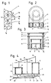
- FIG. 2 shows a plan view and in section of two concentrically arranged hollow cylinders 1 and 2 which are connected to one another via a common end plate 3 and 6.
- the two interior spaces 10 and 11 have feed lines 12 and 13.
- FIG. 3 also shows a device with two concentric hollow cylinders 1 and 2. If the outer hollow cylinder 2 is pressurized (gas, liquid), it expands and its movable base part 7 rises, for example, from position a to a '. The overpressure in the free space 11 initially also acts on the inner hollow cylinder 1 as an external overpressure. If the inner hollow cylinder 1 is now filled with a pressure medium or stretched from b to b 'by a rod 14, this at the same time also causes the outer hollow cylinder to expand further from a' to a ", transmitted by the medium therein. Its filling pressure and In addition to the spring rates of the two hollow cylinders, compressibility determines the overall characteristic of the accumulator or the spring of FIG. 3, which is thus adjustable during operation.
- Hollow cylinders assigned to one another in pairs can be designed as a pump construction in that both hollow cylinders act as a tandem, in which case an external drive is required, or in that one hollow cylinder can serve as a motor drive and the other as a pumping working medium.
- FIGS. 4 to 6 show some exemplary embodiments.
- two hollow cylinders 1 and 2 fastened on a base plate 3 next to one another with some intermediate space are each connected to a pressure line 15 and a suction line 16, preferably via one-way valves.
- the movable floor parts 6 are fastened to a centrally mounted swivel beam 20 via joints 19. If the beam bearing 19 is raised by the extension length 18 with the aid of the support 17, both hollow cylinders are stretched or preloaded by the amount 18 with the same dimensions.
- 2 x 18 is the total stroke 21 of each of the hollow cylinders, their unextended length is designated by 22.
- the two cylinders 1 and 2 do not have to be the same size, but can differ in size and stroke if the rotary actuator is adapted accordingly. If the pressure and suction lines are exchanged and the valves are controlled in a stroke-dependent manner, the arrangement shown in FIG. 4 can also serve as a pneumatic or hydraulic two-piston motor.
- FIG. 5 two different hollow cylinders 1 and 2 are arranged one above the other and connected by a common movable bottom part 7.
- the one-sided extended, resting bottom parts are connected to the ends of a cross member 25 so that the two hollow cylinders prestress each other.
- the preload stroke of the hollow cylinder 1 is greater than that of the hollow cylinder 2, as indicated by 26 and 27.
- the lower hollow cylinder 2 is alternately filled and emptied with a pressure medium via the feed line 8.
- the permissible stroke corresponds to the preload stroke amount 26 and is also the delivery stroke of the pumping hollow cylinder 1.
- FIG. 6 shows a pump of a similar design, in which, however, the two hollow cylinders 1 and 2 are flowed through by the conveying medium, without reversing direction.
- the mutually facing base parts 3 and 6 are connected by a coupling rod 30 and together by a pivot lever 31 which swings about its pivot bearing 19 arranged on the cross member 25, up and down.
- the lower hollow cylinder 2 is equipped with a suction port 24 with a check valve and serves as a pump chamber.
- the connecting pipe 29 leading to the upper hollow cylinder 1 is also provided with a check valve and serves as a pressure port.
- the interior of the upper hollow cylinder 1 serves as a compensation space for the medium flowing through it.
- Fig. 7 shows a hollow cylinder construction as a shock absorber or spring element.
- a weakly dimensioned hollow cylinder 1 is arranged above a stationary base part 3 and a more dimensionally dimensioned hollow cylinder 2 is arranged below it. They are connected to one another through the opening 29.
- Port 8 enables the two hollow cylinders to be pressurized as required.
- the upper hollow cylinder 1 experiences a preload stroke 21, which is available as a spring stroke with respect to the plate 34 for forces K which act from above.
- the elastic spring force is provided by the lower hollow storage 2, back vibrations can be limited by stops 35 for the movable bottom part of the hollow cylinder 1.
- Fig. 8 shows a combination of a piston pump and a hollow cylinder 1 with a membrane to a completely leak-free metering pump.
- the membrane 36 is tightly connected to the rod 14 of the piston 37 and separates two liquids at the same pressure, namely on the one hand that Via the exchange line 32 or via the annular gap between the piston 37 and the cylinder 39, the medium which has penetrated, on the other hand, a transfer liquid which is filled in via the connector 8 and is inert for the elastomer.
- Figures 9 and 10 show two pressure accumulators, preferably for pulsation damping.
- the storage function is performed by a hollow cylinder 1
- a pressure-operated membrane 36 serves as a separating element in FIG. 9.
- a and B or A 'and B' indicate the empty or filled position of the pressure accumulator.
- a bellows, folding cylinder or shaft cylinder 38 is provided instead of the membrane.
- the cover of the bellows can be firmly connected to the movable bottom part 6 of the hollow cylinder 1. If, however, the bellows is to be operated without pressure, the space 11 between the bellows 38 and the hollow cylinder 1 is to be filled with a transmission liquid, as shown.
- the stroke 26 of the bellows is larger than the stroke 27 of the hollow cylinder 1 because of its smaller cross section.
- FIG. 11 shows a pump in which a piston 37 is rigidly connected to the movable bottom part 6 of a hollow cylinder 1 of larger diameter via coupling rods 30.
- the cylinder-piston unit 37, 39 is operated in that the interior 4 of the hollow cylinder 1 is expanded via port 8 by compressed air and expands again after pressure relief. If the connections are modified accordingly, the piston can also serve hydraulically as a drive and the hollow cylinder can be used as a pump chamber.
- the pressure transmission ratio in the respective operating mode results from the ratio of the cross sections of piston 37 and hollow cylinder 1.
- the pump arrangement according to FIG. 12 contains the features of FIGS. 6 and 8 according to the invention. It represents a hermetically sealed piston pump through which there is no reversal of direction.
- FIGS. 13 and 14 show examples of a pneumatic or hydraulic working cylinder.
- a piston 37 slides in a cylinder 39 provided with two connections 8, 24.
- the piston rod 59 is guided through a sleeve 61 by means of a non-sealing slide bearing.
- a hollow cylinder with a small cross-section 60 provides sealing to the outside in that it is fastened on the one hand to the piston rod 59 and on the other hand to the bottom of the cylinder 39 on the piston rod side.
- 13 shows the sealing cylinder 60, which moves like the piston 37, in the most extended position.
- the 14 also has two pressure chambers with the connections 8, 24 for the pressure-dependent movement of the piston rod 59.
- the piston 37 instead of the piston 37, however, it has an expansion cylinder 66 which has a much larger diameter than the sealing expansion cylinder 60 and the in the rigid cylinder 39 is housed.
- the resting bottom part 3 of the drive cylinder 66 coincides with the bottom of the cylinder 39 facing away from the piston rod, the other bottom, penetrated centrally by the piston rod 59, is firmly connected to the bottom.
- the cylinder 39 has a slide bearing 51 on one floor and a guide sleeve 62 for the piston rod 59 on the opposite floor.
- the combination of a hollow cylinder with a rigid pressure chamber also shows the pump shown in FIG. 15.
- the hollow cylinder 1 preloaded by a coil spring 33 is driven by pulsating excess pressure in the container 50 provided with the feed line 8.
- the resulting pumping action in the interior 4 of the expansion cylinder 1 is transmitted to the delivery medium through the membrane 36, which in turn is operated without pressure.
- the hollow cylinder 1 can also be driven mechanically via the rod 14.
- the biasing spring 33 and the outer housing 50 are omitted for simplification.
- the arrangement shown in FIG. 15 can also be operated as a hydraulic motor.
- the hollow cylinder 1 by rhythmically changing pressure one of connections 15, 16 to resp. removed hydraulic fluid moves back and forth and transmits its axial movements to the lifting rod 14, which can drive a crank.
- the membrane 36 has the task of contacting the elastomer of the hollow cylinder 1 with the pressure fluid, for. B. prevent hydraulic oil.
- FIG. 16 refers to suggested dimensions for the adhesive connection of the hollow cylinder ends to flange-shaped base parts made of metal or plastic of corresponding strength.
- 53 is the wall thickness of the expansion cylinder 1.
- dimension 54 is approximately the same as 53
- dimension 55 is approximately twice as large. If the flange is to be made entirely of rubber and is to be held by a clamping ring, it is advantageous for the absorption of the expansion forces if the dimension 63 is also approximately the same size as 53. If a vulcanization connection is used instead of or in addition to such clamping, for example with a ring of width 55, its thickness 63 may also be smaller than dimension 53, according to the static requirements. Incidentally, it may be expedient to direct one flange outwards and the opposite flange into the interior of the expansion hose.
- FIGS. 17 to 22 show precautions for executing multidimensional movements of hollow cylinders.
- Fig. 18 shows an expansion cylinder 1 with a movable bottom part 6, on which a rod is attached with a connecting eye.
- a stop 35 is attached in such a way that it comes into contact with its cover 6 after an initially straight initial stroke of the hollow cylinder 1 and thereby prevents further expansion on this side of the hollow cylinder.
- the movable base 6 performs a lateral pivoting movement.
- the different positions of the connecting eyes are marked by a, b and c.
- the hollow cylinder 1 is connected via guide pieces 41 to a guide rail or curve such that the free hollow cylinder end follows the guide rail 40 in its movements.
- FIG. 19 An axially elastic hollow cylinder is shown in FIG. 19, which simultaneously expands and curves laterally when the filling pressure is increased. This is achieved in that a clamping element 42 is laid on the inside of the hollow cylinder 1, which connects the two bottom parts 6.7 of the expansion cylinder 1 with each other.
- the sequence of movements of the movable hollow cylinder end can be changed or influenced over a wide range by the placement of the clamping element or a combination of clamping aids.
- the hollow cylinder 1 can be fastened on a base plate 64, in which a pivot point or pivot bearing 45 is provided at a distance from the center 65 of the base surface of the hollow cylinder.
- a pivot point or pivot bearing 45 is provided at a distance from the center 65 of the base surface of the hollow cylinder.
- Another possibility is to attach guide rollers or sliding elements 44 to the hollow cylinder, which are guided by guide rails or sliding surfaces 43.
- the guidance of the free end and all sections of the hollow cylinder can also be effected by combining the devices described above. In any case, as is shown in FIG. 20 by the arrangement of the guide rails 43, care must also be taken to ensure that the pivoting cylinder cannot move out of the pivoting plane under the action of opposing forces on its movable end.
- 21 indicates the possibility of giving a hollow cylinder 1 guided on spokes 46 a straight cylindrical shape in its fully expanded position. This is achieved in that the hollow cylinder 1 is fastened to the spokes 46 in a pre-curved manner.
- a spatial manipulator is shown in FIG. 22.
- a plurality of hollow cylinders 1, if necessary, rigidly engage the corner of a manipulation frame 48, 49 and bring it into the desired positions by filling the individual hollow cylinders 1 with different strengths.
Landscapes
- Engineering & Computer Science (AREA)
- Mechanical Engineering (AREA)
- Physics & Mathematics (AREA)
- Fluid Mechanics (AREA)
- General Engineering & Computer Science (AREA)
- Actuator (AREA)
- Reciprocating Pumps (AREA)
Claims (16)
Applications Claiming Priority (4)
| Application Number | Priority Date | Filing Date | Title |
|---|---|---|---|
| DE3444978 | 1984-12-10 | ||
| DE19843444978 DE3444978A1 (de) | 1984-12-10 | 1984-12-10 | Vorrichtung zur speicherung bzw. uebertragung von energie |
| DE19853523717 DE3523717A1 (de) | 1985-07-03 | 1985-07-03 | Dehnzylinder mit elastisch veraenderbarer laenge |
| DE3523717 | 1985-07-03 |
Publications (3)
| Publication Number | Publication Date |
|---|---|
| EP0185953A2 EP0185953A2 (fr) | 1986-07-02 |
| EP0185953A3 EP0185953A3 (en) | 1986-10-22 |
| EP0185953B1 true EP0185953B1 (fr) | 1989-03-15 |
Family
ID=25827217
Family Applications (1)
| Application Number | Title | Priority Date | Filing Date |
|---|---|---|---|
| EP85115045A Expired EP0185953B1 (fr) | 1984-12-10 | 1985-11-27 | Cylindre de dilatation avec une longueur élastiquement variable |
Country Status (3)
| Country | Link |
|---|---|
| US (1) | US4995304A (fr) |
| EP (1) | EP0185953B1 (fr) |
| DE (1) | DE3568834D1 (fr) |
Families Citing this family (4)
| Publication number | Priority date | Publication date | Assignee | Title |
|---|---|---|---|---|
| DE4318553C2 (de) * | 1993-06-04 | 1995-05-18 | Daimler Benz Ag | Adaptiver hydropneumatischer Pulsationsdämpfer |
| WO2005021980A1 (fr) * | 2003-08-29 | 2005-03-10 | Matsushita Electric Industrial Co., Ltd. | Actionneur a pression de fluide compressible |
| US10655652B1 (en) * | 2019-04-10 | 2020-05-19 | Revolutionary Power Llc | Reciprocal motion fluid cylinder assembly |
| WO2023203662A1 (fr) * | 2022-04-20 | 2023-10-26 | リバーフィールド株式会社 | Procédé de fixation d'actionneur souple et unité d'actionneur souple |
Family Cites Families (17)
| Publication number | Priority date | Publication date | Assignee | Title |
|---|---|---|---|---|
| FR1317932A (fr) * | 1963-05-10 | |||
| US2464095A (en) * | 1945-02-07 | 1949-03-08 | William L Nies | Pump |
| GB971556A (en) * | 1961-03-01 | 1964-09-30 | Gen Electric | Improvements in fluid pressure servomotors |
| US3492946A (en) * | 1968-05-23 | 1970-02-03 | Union Carbide Corp | Dual volume fluid sample pump |
| DE1751865A1 (de) * | 1968-08-09 | 1971-08-19 | Rich Stanley Robert | Motorelement |
| US3839945A (en) * | 1972-05-05 | 1974-10-08 | Greer Hydraulics Inc | Rotary actuator |
| GB1404505A (en) * | 1972-09-28 | 1975-08-28 | Jaffray B J | Lifting air bag for the turning of loads |
| US3945770A (en) * | 1973-01-05 | 1976-03-23 | Welker Robert H | High pressure pump |
| DE2412458A1 (de) * | 1973-04-19 | 1974-11-07 | Rudolf Felix Dipl In Homberger | Vorrichtung mit mindestens einer druckmedium betaetigbaren einheit |
| DE2601831C3 (de) * | 1975-01-31 | 1979-08-02 | Jan Edvard Nacka Persson (Schweden) | Pumpe |
| GB1555957A (en) * | 1977-02-28 | 1979-11-14 | Secr Defence | Liquid pumps |
| DE2823697A1 (de) * | 1978-05-31 | 1979-12-06 | Transform Verstaerkungsmasch | Verfahren zum umformen pneumatischer oder hydraulischer energie oder umgekehrt und vorrichtung zur durchfuehrung des verfahrens |
| JPS5686208A (en) * | 1979-12-14 | 1981-07-13 | Nakayama Tekkosho:Kk | Elastic body constitution ram |
| US4525127A (en) * | 1981-01-05 | 1985-06-25 | Welker Engineering Company | Fluid pump mechanism |
| GB2100826B (en) * | 1981-06-18 | 1985-01-03 | Ferranti Ltd | Remotely-controlled arm |
| EP0123558B1 (fr) * | 1983-04-25 | 1990-11-14 | Bridgestone Corporation | Actionneur pneumatique pour manipulateur |
| US4769992A (en) * | 1986-12-30 | 1988-09-13 | Matsushita Electric Industrial Co., Ltd. | Reciprocation apparatus with sealing mechanism |
-
1985
- 1985-11-27 EP EP85115045A patent/EP0185953B1/fr not_active Expired
- 1985-11-27 DE DE8585115045T patent/DE3568834D1/de not_active Expired
-
1987
- 1987-12-28 US US07/117,048 patent/US4995304A/en not_active Expired - Fee Related
Also Published As
| Publication number | Publication date |
|---|---|
| DE3568834D1 (en) | 1989-04-20 |
| EP0185953A3 (en) | 1986-10-22 |
| US4995304A (en) | 1991-02-26 |
| EP0185953A2 (fr) | 1986-07-02 |
Similar Documents
| Publication | Publication Date | Title |
|---|---|---|
| EP2498982B1 (fr) | Presse | |
| DE2502566C3 (de) | Membranpumpe | |
| DE69937809T2 (de) | Vorrichtung bestehend aus der kombination einer kammer mit einem kolben | |
| EP0438428A1 (fr) | Pompe a soufflet a double action. | |
| EP2912310B1 (fr) | Pompe à piston membrane | |
| WO2020225205A1 (fr) | Amortisseur de vibrations comprenant deux dispositifs de soupape d'amortissement ajustables | |
| DE2255413A1 (de) | Steuerschieber fuer druckmedien | |
| DE102009036663B4 (de) | Innenhochdruckumformwerkzeug und ein Verfahren zum Betreiben dessen | |
| EP0177850A1 (fr) | Vérin hydraulique sans tige | |
| DE2355191C3 (de) | Kolbenpumpe | |
| DE485647T1 (de) | Hydraulisch betaetigter reibungsdaempfer. | |
| DE102005053394B4 (de) | Schwingungsdämpfer mit verstellbarer Dämpfkraft | |
| DE69908960T2 (de) | Niederdruck- betätigungsglied | |
| EP0185953B1 (fr) | Cylindre de dilatation avec une longueur élastiquement variable | |
| DE2421487A1 (de) | Membranpumpe | |
| DE3920293A1 (de) | Kolben-zylinder-aggregat | |
| DE2939153A1 (de) | Stroemungsmittelbetriebener linearantrieb fuer ein mit grossem hub geradlinig bewegtes abtriebsglied | |
| DE3444978A1 (de) | Vorrichtung zur speicherung bzw. uebertragung von energie | |
| DE3523717A1 (de) | Dehnzylinder mit elastisch veraenderbarer laenge | |
| AT410357B (de) | Arbeitszylinder | |
| EP0160340B1 (fr) | Appareil de radiologie muni d'une partie coulissante | |
| CH652805A5 (de) | Druckumsetzer mit mindestens drei oelhydraulisch angetriebenen kolben. | |
| DE3215795C2 (de) | Druckmittelbeaufschlagbarer Arbeitszylinder | |
| DE1755079B2 (de) | Hydropneumatische federung fuer fahrzeuge | |
| DE2101963C3 (de) | Axialkolbenmaschine mit veränderbarem Hubvolumen |
Legal Events
| Date | Code | Title | Description |
|---|---|---|---|
| PUAI | Public reference made under article 153(3) epc to a published international application that has entered the european phase |
Free format text: ORIGINAL CODE: 0009012 |
|
| AK | Designated contracting states |
Kind code of ref document: A2 Designated state(s): DE FR GB IT |
|
| PUAL | Search report despatched |
Free format text: ORIGINAL CODE: 0009013 |
|
| AK | Designated contracting states |
Kind code of ref document: A3 Designated state(s): DE FR GB IT |
|
| 17P | Request for examination filed |
Effective date: 19870202 |
|
| 17Q | First examination report despatched |
Effective date: 19870724 |
|
| ITF | It: translation for a ep patent filed | ||
| GRAA | (expected) grant |
Free format text: ORIGINAL CODE: 0009210 |
|
| AK | Designated contracting states |
Kind code of ref document: B1 Designated state(s): DE FR GB IT |
|
| GBT | Gb: translation of ep patent filed (gb section 77(6)(a)/1977) | ||
| REF | Corresponds to: |
Ref document number: 3568834 Country of ref document: DE Date of ref document: 19890420 |
|
| ET | Fr: translation filed | ||
| PLBE | No opposition filed within time limit |
Free format text: ORIGINAL CODE: 0009261 |
|
| STAA | Information on the status of an ep patent application or granted ep patent |
Free format text: STATUS: NO OPPOSITION FILED WITHIN TIME LIMIT |
|
| 26N | No opposition filed | ||
| ITTA | It: last paid annual fee | ||
| PGFP | Annual fee paid to national office [announced via postgrant information from national office to epo] |
Ref country code: FR Payment date: 19921007 Year of fee payment: 8 |
|
| PGFP | Annual fee paid to national office [announced via postgrant information from national office to epo] |
Ref country code: GB Payment date: 19921029 Year of fee payment: 8 |
|
| PGFP | Annual fee paid to national office [announced via postgrant information from national office to epo] |
Ref country code: DE Payment date: 19931021 Year of fee payment: 9 |
|
| PG25 | Lapsed in a contracting state [announced via postgrant information from national office to epo] |
Ref country code: GB Effective date: 19931127 |
|
| GBPC | Gb: european patent ceased through non-payment of renewal fee |
Effective date: 19931127 |
|
| PG25 | Lapsed in a contracting state [announced via postgrant information from national office to epo] |
Ref country code: FR Effective date: 19940729 |
|
| REG | Reference to a national code |
Ref country code: FR Ref legal event code: ST |
|
| PG25 | Lapsed in a contracting state [announced via postgrant information from national office to epo] |
Ref country code: DE Effective date: 19950801 |