EP0186167B1 - Clapet d'écoulement à réglage électromagnétique - Google Patents
Clapet d'écoulement à réglage électromagnétique Download PDFInfo
- Publication number
- EP0186167B1 EP0186167B1 EP19850116408 EP85116408A EP0186167B1 EP 0186167 B1 EP0186167 B1 EP 0186167B1 EP 19850116408 EP19850116408 EP 19850116408 EP 85116408 A EP85116408 A EP 85116408A EP 0186167 B1 EP0186167 B1 EP 0186167B1
- Authority
- EP
- European Patent Office
- Prior art keywords
- plunger
- control valve
- directional control
- electromagnetic directional
- electromagnetic
- Prior art date
- Legal status (The legal status is an assumption and is not a legal conclusion. Google has not performed a legal analysis and makes no representation as to the accuracy of the status listed.)
- Expired - Lifetime
Links
- 230000007935 neutral effect Effects 0.000 claims description 13
- 239000000696 magnetic material Substances 0.000 claims description 5
- 239000012530 fluid Substances 0.000 claims description 2
- 230000002093 peripheral effect Effects 0.000 description 3
- 230000001105 regulatory effect Effects 0.000 description 3
- 230000000694 effects Effects 0.000 description 2
- 230000003213 activating effect Effects 0.000 description 1
- 230000006835 compression Effects 0.000 description 1
- 238000007906 compression Methods 0.000 description 1
- 230000001276 controlling effect Effects 0.000 description 1
- 230000001934 delay Effects 0.000 description 1
- 230000003292 diminished effect Effects 0.000 description 1
- 238000006073 displacement reaction Methods 0.000 description 1
- 230000005284 excitation Effects 0.000 description 1
- 239000007788 liquid Substances 0.000 description 1
- 238000007789 sealing Methods 0.000 description 1
Images

Classifications
-
- B—PERFORMING OPERATIONS; TRANSPORTING
- B60—VEHICLES IN GENERAL
- B60G—VEHICLE SUSPENSION ARRANGEMENTS
- B60G17/00—Resilient suspensions having means for adjusting the spring or vibration-damper characteristics, for regulating the distance between a supporting surface and a sprung part of vehicle or for locking suspension during use to meet varying vehicular or surface conditions, e.g. due to speed or load
- B60G17/06—Characteristics of dampers, e.g. mechanical dampers
- B60G17/08—Characteristics of fluid dampers
-
- F—MECHANICAL ENGINEERING; LIGHTING; HEATING; WEAPONS; BLASTING
- F16—ENGINEERING ELEMENTS AND UNITS; GENERAL MEASURES FOR PRODUCING AND MAINTAINING EFFECTIVE FUNCTIONING OF MACHINES OR INSTALLATIONS; THERMAL INSULATION IN GENERAL
- F16F—SPRINGS; SHOCK-ABSORBERS; MEANS FOR DAMPING VIBRATION
- F16F9/00—Springs, vibration-dampers, shock-absorbers, or similarly-constructed movement-dampers using a fluid or the equivalent as damping medium
- F16F9/32—Details
- F16F9/44—Means on or in the damper for manual or non-automatic adjustment; such means combined with temperature correction
- F16F9/46—Means on or in the damper for manual or non-automatic adjustment; such means combined with temperature correction allowing control from a distance, i.e. location of means for control input being remote from site of valves, e.g. on damper external wall
- F16F9/466—Throttling control, i.e. regulation of flow passage geometry
-
- Y—GENERAL TAGGING OF NEW TECHNOLOGICAL DEVELOPMENTS; GENERAL TAGGING OF CROSS-SECTIONAL TECHNOLOGIES SPANNING OVER SEVERAL SECTIONS OF THE IPC; TECHNICAL SUBJECTS COVERED BY FORMER USPC CROSS-REFERENCE ART COLLECTIONS [XRACs] AND DIGESTS
- Y10—TECHNICAL SUBJECTS COVERED BY FORMER USPC
- Y10T—TECHNICAL SUBJECTS COVERED BY FORMER US CLASSIFICATION
- Y10T137/00—Fluid handling
- Y10T137/8593—Systems
- Y10T137/86493—Multi-way valve unit
- Y10T137/86574—Supply and exhaust
- Y10T137/86622—Motor-operated
-
- Y—GENERAL TAGGING OF NEW TECHNOLOGICAL DEVELOPMENTS; GENERAL TAGGING OF CROSS-SECTIONAL TECHNOLOGIES SPANNING OVER SEVERAL SECTIONS OF THE IPC; TECHNICAL SUBJECTS COVERED BY FORMER USPC CROSS-REFERENCE ART COLLECTIONS [XRACs] AND DIGESTS
- Y10—TECHNICAL SUBJECTS COVERED BY FORMER USPC
- Y10T—TECHNICAL SUBJECTS COVERED BY FORMER US CLASSIFICATION
- Y10T137/00—Fluid handling
- Y10T137/8593—Systems
- Y10T137/86493—Multi-way valve unit
- Y10T137/86718—Dividing into parallel flow paths with recombining
- Y10T137/86759—Reciprocating
- Y10T137/86791—Piston
-
- Y—GENERAL TAGGING OF NEW TECHNOLOGICAL DEVELOPMENTS; GENERAL TAGGING OF CROSS-SECTIONAL TECHNOLOGIES SPANNING OVER SEVERAL SECTIONS OF THE IPC; TECHNICAL SUBJECTS COVERED BY FORMER USPC CROSS-REFERENCE ART COLLECTIONS [XRACs] AND DIGESTS
- Y10—TECHNICAL SUBJECTS COVERED BY FORMER USPC
- Y10T—TECHNICAL SUBJECTS COVERED BY FORMER US CLASSIFICATION
- Y10T137/00—Fluid handling
- Y10T137/8593—Systems
- Y10T137/86493—Multi-way valve unit
- Y10T137/86718—Dividing into parallel flow paths with recombining
- Y10T137/86759—Reciprocating
- Y10T137/86791—Piston
- Y10T137/86799—With internal flow passage
Definitions
- This invention relates to an electromagnetic directional control valve capable of changing over flow paths of fluid to three different positions and, more particularly to a compact electromagnetic directional control valve which can be housed in a tubular member having a relatively small size such as a piston rod.
- a prior electromagnetic directional control valve as disclosed in the US-PS 3 701 366 In the case of this known valve a plunger is provided for opening and closing the flow paths. This plunger is held in its neutral position by means of the biasing means. At both sides of the plunger electromagnetic means are provided in the axial direction; by activating them the plunger is adjustable in one axial direction. An actuating member, which is displaced axially when the corresponding electromagnetic means is activated and at least partly transmits this axial displacement to the plunger by means of mechanical engagement of its pusher with its plunger, serves to adjust the plunger in each case. By means of the thus effected axial shift of the plunger the flow paths of the valve are opened and closed.
- the plunger serves exclusively as a valve element. Its actuation is effected by means of the two actuating members.
- One actuating member is disposed in the axial direction on the right side of the plunger, the other on the left side of the plunger.
- every actuating member is fixedly connected to the corresponding pusher extending in the axial direction.
- an electromagnetic directional control valve in which, the plunger is made of magnetic material and has flow paths capable of affording communication with the flow path provided in the tubular case.
- the plunger serves as a valve body.
- this plunger or valve body is actuated immediately and directly by the electromagnetic means, i.e. without interposing any kind of actuating members. Delays between the excitation of the electromagnetic means and the adjustment of the plunger are eliminated. It is no longer necessary to dispose actuating members between the plunger and the electromagnetic means.
- the electromagnetic directional control valve according to the subject matter of the application can be built significantly smaller and more compact compared to the prior art.
- Reference numeral 10 designates a yoke serving as a case and made generally cylindrically.
- a first electromagnetic means having a first bobbin 11A including a cylindrical portion, a first coil 12A and a first core 13A is fixed to an upper interior of the yoke 10.
- a first sleeve 14A made of non-magnetic material.
- a second electromagnetic means having a second bobbin 11B, a second coil 12B and a second core 13B is fixed to a lower interior ofthe yoke 10 coaxially with the first electromagnetic means.
- a second sleeve 14B is fixed to the inside of the cylindrical portion of the second bobbin 11B.
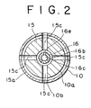
- a third cylindrical core 15 formed radially with four first ports 15c.
- the yoke 10 is formed on an inner peripheral surface with an annular groove 10a, from which are provided four holes 10b to an outer peripheral surface. Therefore, a necessary area of flow path is ensured even if the third core 15 is rotated to move the port 15c out of the hole 10b of the yoke 10.
- a cylindrical plunger 16 made of magnetic material is movably housed inside of the third core 15.
- the plunger 16 is formed on an outer peripheral surface at an axial interval with annular grooves 16a,16b. Three orifices 16d,16e are radially formed to afford communication between a flow path 16c provided in the plunger 16 and said annular grooves 16a,16b respectively.
- the plunger 16 serves also as a valve body.
- Each of the orifices 16d is different from each of the orifices 16e in the size of bore so that different quantity of liquid can flow therethrough. All of orifices 16e do not align with all of ports 15c even if the plunger 16 is rotated, since the number of orifices 16e differs from that of the ports 15c. As a result, change of flow resistance hardly occurs.
- the plunger 16 is provided on both ends with a first non-magnetic stopper 17A moved from a neutral position of the plunger in one axial direction together with the plunger 16 and a second non-magnetic stopper 17B moved from the neutral position in the other axial direction together with the plunger 16.
- the first and second stoppers 17A,17B are pressed to bear against the end faces of the plunger 16 respectively by first and second springs 18A,18B supported by the first and second cores 13A,13B and having relatively small spring constant respectively.
- the first stopper 17A is regulated not to move from a position in which it contacts one end 15a of said third core 15 to the lower portion of Fig. 1, i.e., toward the second electromagnetic means.
- the second stopper 17B is regulated not to move from a position in which it contacts the other end 15b of the third core 15 toward the first electromagnetic means. Under these conditions occupies the plunger 16 the neutral position.
- reference numeral 13c designates a flow path provided in the center of the second core 13B, 19 a sealing O-ring, 20 a second port formed in the yoke 10, 21 lead wires for supplying current to the first and second coils 12A,12B and 22 terminals.
- the plunger 16 is pressed by the first and second springs 18A,18B through the first and second stoppers 17A,17B to be located at the first position (hereinafter referred to as the neutral position).
- the first and second ports 15c,20 communicate to each other through the orifices 16e in the plunger 16.
- the plunger 16 When the first coil 12A is excited and the second coil 12B is not excited, the plunger 16 is attracted upward as viewed in Fig. 1. Then the second stopper 17B abuts against the end 15b of the third core 15 to be restrained from the movement above that position so that the plunger 16 is moved easily to the second position (hereinafter referred to as one side position) against only the set load of the spring 18A. As a result, the first and second ports 15c,20 are closed by the plunger 16 into the completely closed condition.
- the plunger 16 is attracted downward as viewed in Fig. 1. Then, the plunger 16, reversely to the above mentioned, is moved easily to the third position (hereinafter refered to as the other side position) against only the set load of the second spring 18B. As a result, the first and second ports 15c,20 will communicate to each other through the orifices 16d in the plunger 16, the path area, i.e., flow resistance of the orifices 16d being different from that of the orifices 16e at said neutral position.
- a directional control valve is provided which is operatively changed over to three positions by controlling the current supply to the first and second coils 12A,12B.
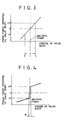
- the prior directional control valve shows characteristics shown in Fig. 3. That is, a press force of the spring constant composed of two springs multiplied by the stroke of movement of the valve body, i.e., the press force proportional to the stroke acts on the valve body.
- a press force of the spring constant composed of two springs multiplied by the stroke of movement of the valve body, i.e., the press force proportional to the stroke acts on the valve body.
- the present invention has characteristics shown by the solid line in Fig. 11. Namely, when the plunger is moved upwardly from the neutral position by a small distance, the second spring 18B is regulated by the second stopper 17B as above described, so that the plunger 16 receives the load P set by the first spring 18A (hereinafter referred to as P for convenience) and when moved, further receives a press force proportional to the stroke (with the spring constant of only the first spring 18A being the proportional constant ). Similarly, when the plunger is moved downwardly, it receives same press force.
- the certain stationary force can be obtained even by reducing the spring constants of the first and second springs 18A,18B so that the present invention has excellent effects of providing the compact first and second coils 12A,12B.
Landscapes
- Engineering & Computer Science (AREA)
- General Engineering & Computer Science (AREA)
- Mechanical Engineering (AREA)
- Magnetically Actuated Valves (AREA)
Claims (8)
- Une électrovalve directionnelle pour commuter les trajets d'écoulement de fluides, comprenant un corps tubulaire (10), des premiers et seconds moyens électromagnétiques (11A, 12A, 13A, 11B, 12B, 13B) fixés avec un espacement axial les uns par rapport aux autres dans ledit corps tubulaire (10) un plongeur (16) disposé dans ledit corps (10) et susceptible d'être déplacé par lesdits premiers moyens électromagnétiques (11A, 12A, 13A) à partir d'une position neutre ou de point mort dans une direction axiale et, dans l'autre direction axiale, par lesdits seconds moyens électromagnétiques (11B, 12B, 13B) pour participer à ladite commutation de trajet d'écoulement, et des premiers et seconds moyens de sollicitation (18A, 18B) pour solliciter ledit plongeur (16) vers sa position de point mort, ledit plongeur (16) définissant également une seconde position vers laquelle ledit plongeur (16) est déplacé dans une direction axiale par lesdits premiers moyens électromagnétiques (11A, 12A, 13A), contre lesdits premiers moyens de sollicitation (18A) et une troisième position vers laquelle ledit plongeur (16) est déplacé dans l'autre direction axiale par lesdits seconds moyens électromagnétiques (11B, 12B, 13B) contre lesdits seconds moyens de sollicitation (18B), caractérisé en ce que ledit plongeur (16) est réalisé en matériau magnétique et qu'ils définit des trajets d'écoulement (16d, 16e) susceptibles d'établir une communication avec les trajets d'écoulement (10b) ménagés dans ledit corps tubulaire (10), le plongeur servant ainsi de corps de valve ou obturateur.
- Une électrovalve directionnelle selon la revendication 1, comprenant en outre un premier élément formant poussoir ou butée d'arrêt (17A) portant contre ledit plongeur (16) et se déplaçant dans une direction axiale avec ledit plongeur (16) et un second élément formant poussoir ou butée d'arrêt (17B) portant contre ledit plongeur (16), et se déplaçant dans l'autre direction axiale avec ledit plongeur (16), lesdits premier et second éléments formant poussoir ou butée d'arrêt (17A, 17B) étant réalisés en matériau amagnétique et étant sollicités par lesdits premiers et seconds moyens de sollicitation (18A, 18B), respectivement, dans les directions de butée dudit plongeur (16).
- Une électrovalve directionnelle selon la revendication 2, dans laquelle ledit plongeur (16) est monté mobile dans un noyau tubulaire (15) et lesdits premier et second éléments formant poussoir ou butée d'arrêt (17A, 17B) viennent en butée contre ledit noyau (15) de manière à empêcher tout déplacement éventuel supplémentaire.
- Une électrovalve directionnelle selon la revendication 3, dans laquelle ledit plongeur (16) occupe sa position de point mort lorsque lesdits premier et second éléments formant poussoir ou butée d'arrêt (17A, 17B), respectivement, portent contre ledit noyau tubulaire (15).
- Une électrovalve directionnelle selon la revendication 2, dans laquelle lesdits premier et second éléments formant poussoir ou butée d'arrêt (17A, 17B), respectivement, portent contre les faces d'extrémité dudit plongeur (16).
- Une électrovalve directionnelle selon l'une quelconque des revendications 1 à 5, dans lequel lesdits trajets d'écoulement du plongeur (16), au nom de deux (16d, 16e), s'étendent diamétralement et sont espacés axialement l'un de l'autre et établissent une communication par l'intermédiaire d'un trajet d'écoulement de grande et de petite section.
- Une électrovalve directionnelle selon la revendication 6, dans la mesure où la revendication 6 vise les revendications 3 et 4, dans laquelle ledit noyau tubulaire (15) définit un trajet d'écoulement (15C) s'étendant radialement et communiquant avec ledit trajet d'écoulement (10b) du corps (10), le trajet d'écoulement (15C) étant susceptible de communiquer avec lesdits deux trajets d'écoulement (16d, 16e).
- Une électrovalve directionnelle selon la revendication 7, dans laquelle lesdits trajets d'écoulement respectifs (16d, 16e) dudit plongeur (16) comportent une pluralité d'orifices, ledit trajet d'écoulement (15C) dudit noyau tubulaire (15) comprenant une pluralité d'orifices, différents de ceux de chacun desdits orifices d'écoulement ménagés dans ledit plongeur (16).
Applications Claiming Priority (4)
| Application Number | Priority Date | Filing Date | Title |
|---|---|---|---|
| JP27396684A JPS61153032A (ja) | 1984-12-27 | 1984-12-27 | 液圧緩衝器 |
| JP273966/84 | 1984-12-27 | ||
| JP87095/85 | 1985-04-23 | ||
| JP8709585A JPS61244985A (ja) | 1985-04-23 | 1985-04-23 | 3位置電磁切換弁 |
Publications (3)
| Publication Number | Publication Date |
|---|---|
| EP0186167A2 EP0186167A2 (fr) | 1986-07-02 |
| EP0186167A3 EP0186167A3 (en) | 1988-07-27 |
| EP0186167B1 true EP0186167B1 (fr) | 1991-09-18 |
Family
ID=26428406
Family Applications (1)
| Application Number | Title | Priority Date | Filing Date |
|---|---|---|---|
| EP19850116408 Expired - Lifetime EP0186167B1 (fr) | 1984-12-27 | 1985-12-20 | Clapet d'écoulement à réglage électromagnétique |
Country Status (3)
| Country | Link |
|---|---|
| US (1) | US4681143A (fr) |
| EP (1) | EP0186167B1 (fr) |
| DE (1) | DE3584151D1 (fr) |
Families Citing this family (35)
| Publication number | Priority date | Publication date | Assignee | Title |
|---|---|---|---|---|
| GB8618301D0 (en) * | 1986-07-26 | 1986-09-03 | Eaton Sa Monaco | Three-port fluid valve |
| DE3635894A1 (de) * | 1986-10-22 | 1988-05-05 | Bosch Gmbh Robert | Stossdaempfer |
| DE3736695C2 (de) * | 1986-10-31 | 1995-03-23 | Atsugi Motor Parts Co Ltd | Stoßdämpfer mit variabler Dämpfung |
| DE3832625C2 (de) * | 1987-10-13 | 1999-06-24 | Hauni Werke Koerber & Co Kg | Schwingungsdämpfer mit veränderbarer Dämpfungscharakteristik |
| US4907680A (en) * | 1988-01-29 | 1990-03-13 | Lord Corporation | Semi-active damper piston valve assembly |
| DE3868398D1 (de) * | 1988-02-15 | 1992-03-26 | Bendix Espana | Daempfer mit veraenderbarer daempfkraft. |
| DE3805934A1 (de) * | 1988-02-25 | 1989-09-07 | Bosch Gmbh Robert | Hydraulischer stossdaempfer |
| FR2627829B1 (fr) * | 1988-02-26 | 1990-08-10 | Applic Mach Motrices | Dispositif amortisseur pour element de suspension hydropneumatique de vehicule, et amortisseur faisant partie de ce dispositif |
| NL8800944A (nl) * | 1988-04-12 | 1989-11-01 | Koni Bv | Stelinrichting met geheugenmetaal en een met deze stelinrichting uitgeruste schokdemper. |
| US4909063A (en) * | 1988-10-24 | 1990-03-20 | The Foxboro Company | Pressure calibration method and apparatus |
| GB2227547B (en) * | 1988-12-14 | 1992-10-28 | Tokico Ltd | Adjustable damping force hydraulic shock absorber |
| JP2964148B2 (ja) * | 1989-04-20 | 1999-10-18 | トキコ株式会社 | 減衰力調整式油圧緩衝器 |
| DE3922891A1 (de) * | 1989-07-12 | 1991-01-17 | Bosch Gmbh Robert | Hydraulischer, regelbarer stossdaempfer |
| DE4033190C1 (fr) * | 1990-10-19 | 1992-01-02 | Mercedes-Benz Aktiengesellschaft, 7000 Stuttgart, De | |
| US5348224A (en) * | 1992-11-24 | 1994-09-20 | Hydro Flame Corporation | Gas flow modulator |
| US5339777A (en) * | 1993-08-16 | 1994-08-23 | Caterpillar Inc. | Electrohydraulic device for actuating a control element |
| US6161770A (en) | 1994-06-06 | 2000-12-19 | Sturman; Oded E. | Hydraulically driven springless fuel injector |
| US6257499B1 (en) | 1994-06-06 | 2001-07-10 | Oded E. Sturman | High speed fuel injector |
| DE69422284T2 (de) * | 1994-09-15 | 2000-05-11 | Yamaha Hatsudoki K.K., Iwata | Hydraulischer Stossdämpfer |
| US5522484A (en) * | 1994-09-16 | 1996-06-04 | Yamaha Hatsudoki Kabushiki Kaisha | Variable damping force hydraulic shock absorber |
| US6148778A (en) | 1995-05-17 | 2000-11-21 | Sturman Industries, Inc. | Air-fuel module adapted for an internal combustion engine |
| US6085991A (en) | 1998-05-14 | 2000-07-11 | Sturman; Oded E. | Intensified fuel injector having a lateral drain passage |
| US6113014A (en) * | 1998-07-13 | 2000-09-05 | Caterpillar Inc. | Dual solenoids on a single circuit and fuel injector using same |
| JP2001012636A (ja) * | 1999-06-29 | 2001-01-16 | Aisan Ind Co Ltd | 複数のソレノイドと共通筒を有する燃料噴射装置 |
| JP3687499B2 (ja) * | 2000-06-30 | 2005-08-24 | 豊田工機株式会社 | 流量制御弁 |
| JP2002130511A (ja) * | 2000-10-26 | 2002-05-09 | Aisin Seiki Co Ltd | 電磁弁 |
| JP3925091B2 (ja) * | 2001-02-28 | 2007-06-06 | 株式会社豊田自動織機 | 容量可変型圧縮機の制御弁及び同制御弁の調整方法 |
| US6957655B2 (en) * | 2002-09-20 | 2005-10-25 | Advanced Neuromodulation Systems, Inc. | Apparatus for dosage control |
| US6677844B1 (en) * | 2002-10-21 | 2004-01-13 | Adams Rite Aerospace, Inc. | Quick-return electro-mechanical actuator |
| DE102005004327A1 (de) * | 2005-01-31 | 2006-08-03 | Robert Bosch Gmbh | Elektrische Trennung in Kraftstoffinjektoren |
| US7921877B2 (en) * | 2007-05-24 | 2011-04-12 | International Engine Intellectual Property Company, Llc | Spool valve and method |
| US8104511B2 (en) * | 2007-08-27 | 2012-01-31 | Parker Hannifin Corporation | Sequential stepped directional control valve |
| US9328841B2 (en) * | 2013-09-17 | 2016-05-03 | Nordson Corporation | Fluid dispenser utilizing dual coils and methods of fluid dispensing |
| US10935158B2 (en) * | 2017-10-10 | 2021-03-02 | Ferplast S.R.L. | Inlet valve locking system for inflatable underwater equipment |
| JP7112356B2 (ja) * | 2019-03-04 | 2022-08-03 | Kyb株式会社 | 緩衝器 |
Family Cites Families (7)
| Publication number | Priority date | Publication date | Assignee | Title |
|---|---|---|---|---|
| US2407184A (en) * | 1942-10-14 | 1946-09-03 | Honeywell Regulator Co | Solenoid valve |
| US3357454A (en) * | 1964-01-20 | 1967-12-12 | Snap Tite Inc | Balanced multi-way valve |
| US3701366A (en) * | 1970-08-14 | 1972-10-31 | Atos Apparecchiature Oleodinam | Hydraulic solenoid valve directly operated with adjustable over-ride speed |
| US3784943A (en) * | 1972-07-19 | 1974-01-08 | Honeywell Inf Systems | Solenoid actuator |
| US4144514A (en) * | 1976-11-03 | 1979-03-13 | General Electric Company | Linear motion, electromagnetic force motor |
| JPS627033Y2 (fr) * | 1981-01-09 | 1987-02-18 | ||
| JPS57115468A (en) * | 1981-01-10 | 1982-07-17 | Orient Kagaku Kogyo Kk | Water-based black ink composition |
-
1985
- 1985-12-20 DE DE8585116408T patent/DE3584151D1/de not_active Expired - Lifetime
- 1985-12-20 EP EP19850116408 patent/EP0186167B1/fr not_active Expired - Lifetime
- 1985-12-24 US US06/813,144 patent/US4681143A/en not_active Expired - Fee Related
Also Published As
| Publication number | Publication date |
|---|---|
| EP0186167A3 (en) | 1988-07-27 |
| EP0186167A2 (fr) | 1986-07-02 |
| US4681143A (en) | 1987-07-21 |
| DE3584151D1 (de) | 1991-10-24 |
Similar Documents
| Publication | Publication Date | Title |
|---|---|---|
| US4681143A (en) | Electromagnetic directional control valve | |
| US4250922A (en) | Electromagnetically operated control valve | |
| CA2347610C (fr) | Electrovanne de reglage de la pression | |
| EP0718532B1 (fr) | Distributeur | |
| US5246033A (en) | Electromagnetically actuatable double seat valve | |
| KR102113102B1 (ko) | 직접 작용식 솔레노이드 작동기 | |
| EP3117131B1 (fr) | Vanne de commande de pompe à huile à gaine double/variable | |
| US6065496A (en) | Electromagnetically operated directional valve | |
| US5868167A (en) | Pressure regulating valve in a hydraulic control system for an automatic transmission | |
| US7422033B2 (en) | Position feedback pilot valve actuator for a spool control valve | |
| EP1463890B1 (fr) | Soupape pneumatique commandee par pilote | |
| US4905961A (en) | Electromagnetic actuator | |
| KR100476246B1 (ko) | 비례압력 제어밸브 | |
| US6557823B2 (en) | Electromagnetic valve | |
| EP0702166B1 (fr) | Amortisseur de chocs hydraulique | |
| JPH0245569Y2 (fr) | ||
| JPH0217258Y2 (fr) | ||
| EP0908654B1 (fr) | Electrovanne pour la régulation de débit | |
| GB2110795A (en) | Electro-pneumatic valve | |
| EP0051591B1 (fr) | Dispositif de reglage electro-hydraulique | |
| JPH01307574A (ja) | 油圧制御弁 | |
| JPS6227315B2 (fr) | ||
| JPH082543Y2 (ja) | 電磁比例圧力制御弁 | |
| JPH04231782A (ja) | 電気機械式装置 | |
| JPS60175878A (ja) | 電磁比例型圧力制御弁 |
Legal Events
| Date | Code | Title | Description |
|---|---|---|---|
| PUAI | Public reference made under article 153(3) epc to a published international application that has entered the european phase |
Free format text: ORIGINAL CODE: 0009012 |
|
| AK | Designated contracting states |
Kind code of ref document: A2 Designated state(s): DE FR GB |
|
| PUAL | Search report despatched |
Free format text: ORIGINAL CODE: 0009013 |
|
| RHK1 | Main classification (correction) |
Ipc: B60G 17/08 |
|
| AK | Designated contracting states |
Kind code of ref document: A3 Designated state(s): DE FR GB |
|
| 17P | Request for examination filed |
Effective date: 19880811 |
|
| 17Q | First examination report despatched |
Effective date: 19881019 |
|
| RAP1 | Party data changed (applicant data changed or rights of an application transferred) |
Owner name: NIPPONDENSO CO., LTD. Owner name: TOYOTA JIDOSHA KABUSHIKI KAISHA |
|
| GRAA | (expected) grant |
Free format text: ORIGINAL CODE: 0009210 |
|
| AK | Designated contracting states |
Kind code of ref document: B1 Designated state(s): DE FR GB |
|
| ET | Fr: translation filed | ||
| REF | Corresponds to: |
Ref document number: 3584151 Country of ref document: DE Date of ref document: 19911024 |
|
| PLBE | No opposition filed within time limit |
Free format text: ORIGINAL CODE: 0009261 |
|
| STAA | Information on the status of an ep patent application or granted ep patent |
Free format text: STATUS: NO OPPOSITION FILED WITHIN TIME LIMIT |
|
| 26N | No opposition filed | ||
| REG | Reference to a national code |
Ref country code: GB Ref legal event code: 746 Effective date: 19930105 |
|
| REG | Reference to a national code |
Ref country code: FR Ref legal event code: DL |
|
| PGFP | Annual fee paid to national office [announced via postgrant information from national office to epo] |
Ref country code: GB Payment date: 19951211 Year of fee payment: 11 |
|
| PGFP | Annual fee paid to national office [announced via postgrant information from national office to epo] |
Ref country code: FR Payment date: 19951212 Year of fee payment: 11 |
|
| PGFP | Annual fee paid to national office [announced via postgrant information from national office to epo] |
Ref country code: DE Payment date: 19951222 Year of fee payment: 11 |
|
| PG25 | Lapsed in a contracting state [announced via postgrant information from national office to epo] |
Ref country code: GB Effective date: 19961220 |
|
| GBPC | Gb: european patent ceased through non-payment of renewal fee |
Effective date: 19961220 |
|
| PG25 | Lapsed in a contracting state [announced via postgrant information from national office to epo] |
Ref country code: FR Effective date: 19970829 |
|
| PG25 | Lapsed in a contracting state [announced via postgrant information from national office to epo] |
Ref country code: DE Effective date: 19970902 |
|
| REG | Reference to a national code |
Ref country code: FR Ref legal event code: ST |