EP0186178A2 - Système d'essuie-glace caché - Google Patents
Système d'essuie-glace caché Download PDFInfo
- Publication number
- EP0186178A2 EP0186178A2 EP85116477A EP85116477A EP0186178A2 EP 0186178 A2 EP0186178 A2 EP 0186178A2 EP 85116477 A EP85116477 A EP 85116477A EP 85116477 A EP85116477 A EP 85116477A EP 0186178 A2 EP0186178 A2 EP 0186178A2
- Authority
- EP
- European Patent Office
- Prior art keywords
- wiper
- actuation
- wiper motor
- signals
- intermittent
- Prior art date
- Legal status (The legal status is an assumption and is not a legal conclusion. Google has not performed a legal analysis and makes no representation as to the accuracy of the status listed.)
- Granted
Links
Images


Classifications
-
- B—PERFORMING OPERATIONS; TRANSPORTING
- B60—VEHICLES IN GENERAL
- B60S—SERVICING, CLEANING, REPAIRING, SUPPORTING, LIFTING, OR MANOEUVRING OF VEHICLES, NOT OTHERWISE PROVIDED FOR
- B60S1/00—Cleaning of vehicles
- B60S1/02—Cleaning windscreens, windows or optical devices
- B60S1/46—Cleaning windscreens, windows or optical devices using liquid; Windscreen washers
- B60S1/48—Liquid supply therefor
- B60S1/481—Liquid supply therefor the operation of at least part of the liquid supply being controlled by electric means
- B60S1/486—Liquid supply therefor the operation of at least part of the liquid supply being controlled by electric means including control systems responsive to a vehicle driving condition, e.g. speed
Definitions
- the present invention relates to a concealed wiper system applicable for use with vehicles wherein the wiper has a mechanism to house the wiper blade in the retracted position by reversing rotation of the wiper motor, more paticularly, it relates to new composition of an intermittent actuation wiper device, a speed sensitive intermittent windshield wiper control, a washer interlocked windshield wiper control, a device to cancel the housing in the winter, and a protection device from wiper motor overload, in said concealed wiper system.
- the desired intermittent pause period is recorded within the microcomputer memory and is operated by means of a switch or similar device controlled by the vehicle operator (1983 publication No. 171756).
- a limitation of the existing device is the necessity for the operator to reset the intermittent pause period when restarting the vehicle due to loss of memory content when the power source to the microcomputer is cut at the time the vehicle is stopped.
- a device to eliminate the aforementioned limitation has been proposed (1983 publication No. 171758) wherein multiple pause periods may be selected by means of a pause period selection switch.
- This device can select various oscillation frequencies by means of a combination of oscillators and variable resistors whereby the oscillation signal of the selected frequency is converted to a corresponding voltage by means of a frequency-voltage converter, said voltage being controlled by a microcomputer and compared with a reference voltage by means of a comparator to determine the intermittent pause period.
- the aforementioned device possesses the limitation of requiring a comparator which can select a prescribed number of intermittent pause periods, and possesses the further limitation of requiring a frequency-voltage converter device.
- a still further limitation of the aforesaid device is that it cannot continuously create intermittent pause periods the duration of which correspond to the volume of rainfall, or a vehicle speed.
- the timing periods for every system, are dispersed due to dispersion of the condenser capacity and resistance value elements, and the effects of voltage and temperature also cause variations in the timing period.
- the wiper's wiping frequency during the washer interlocked actuation period is unstable and subject to variation.
- a further limitation includes variations in wiper rotation speed due to friction between the wiper blade and the windshield glass which leads to variations in the wiper's wiping frequency during periods of interlocked actuation.
- a limitation of this construction is the requirement of a circuit breaker within the wiper motor, because a bimetal composition is utilized, the load conditions during circuit breaker actuation are affected by external temperature and motor temperature, resulting in aberrant performance.
- a further limitation is the greatly-dispersed recovery time due to external temperatures.
- a still further limitation is the increasingly complicated construction as extra contacts become necessary in the circuit breaker in order to notify the vehicle operator of circuit breaker actuation.
- Another object of the invention is to provide a concealed wiper system wherein the vehicle operator can optionally determine an intermittent pause period, and wherein once the intermittent pause period have been determined, the determined values are maintained even when the power source is cut.
- Another object of the present invention is to provide a concealed wiper system wherein the intermittent pause period can be automatically varied in accordance to vehicle speed and based upon the operator-determined intermittent pause period.
- This invention has as an another object the provision of a concealed wiper system, wherein washing solution discharge is reliably interlocked with the wiper's wiping action.
- This invention has as still another object the provision of a concealed wiper system, which can override the housing function by means of a simple switch operation.
- Fig. 14 is a flow chart showing the another overload detection sub-routine.
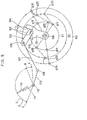
- the wiper motor position detector 2 in this embodiment consists of the motor gear 1D made of synthetic resin in the final reduction stage of wiper motor 1, the pattern plate 7 (metal) fastened to the side of said motor gear, and the contact levers 8A, 8B and 8C on the front of said pattern plate 7 the protruding ends of which, under their own spring action, make suitable contact under oscillating contact movement.
- These contact levers are secured to gear cover lE by means of contact bush 9, and each of the levers is connected with lead wires 10A, 10B and 10C, respectively.
- Pattern plate 7 is formed by the three zones ZA, ZB and ZC consisting of concentric circles with different radii; two zones (ZA, ZB) form a part of a circle, while the other zone (ZC) is a circle itself.
- the three zones (ZA, ZB, ZC) form one body so as to interconnect.
- the contact levers 8A and 8B are arranged so that they have different radial positions in relation to the center of wiper motor 1 output shaft 100, making it feasible for the respective zones ZA, ZB and ZC on the motor gear 1D flank to be contacted with oscillation.
- the other contact lever, 8C is positioned radially so that contact can be made with the circular zone ZC under osciallation.
- contact lever 8C is grounded through the lead wire 10C, and pattern plate 7 is given either a negative or a positive potential.
- pattern plate 7 and contact levers 8A and 8B form a switch system to open and close in terms of the ratational position of the output shaft 100 in the wiper motor 1.
- the protruding end of contact levers 8A and 8B, respectively form contact 2A and 2B, respectively, of the wiper position detector.
- On the front of pattern plate 7 and the motor gear 1D is grease lubrication to reduce friction by contact lever 8A, 8B and 8C.
- Fig. 3 is a table indicating signal outputs summarizing operations of the position detector 2.
- the wiper motor which drives the wiper is a motor equipped with a reduction gear, and said motor incorporates a position.detector 2 for a windshield wiper enabling it to detect the output shaft position.
- Said wiper motor 1 is a DC type with three brushes (low-speed brush lA, high-speed brush lB, and common brush 1C). By brush selection switching one can choose two modes of operation, either at low or high speed.
- Position detector 2 is a switch which opens and closes in accordance with the position of the output shaft 100, of wiper motor 1, and it has contacts 2A and 2B. Said contacts, as described earlier, are arranged to be both closed in the output shaft retracted stop position, open and closed in the intermittent pause position, closed and open in the reverse position, and both open in the median position other than the above three positions. Position detector 2 can output two-bit position signals for the output shaft position.
- Wiper actuation switch 3 is a four-way switch settable to retracted stop actuation (OFF), intermittent actuation (INT), low-speed actuation (LOW), and high-speed actuation (HIGH).
- OFF retracted stop actuation
- INT intermittent actuation
- LOW low-speed actuation
- HGH high-speed actuation
- terminal 3A, 3B and 3C open and close in relation to each other as follows: OFF position (open, open), INT position (open, closed), LOW position (closed, closed), HIGH position (closed, open).
- the wiper actuation switch 3 can be set to the given position by means of two-bit selected signal outputs.
- Control unit 4 has the microcomputer 5 and the wiper motor drive circuit 6.
- Microcomputer 5 is a conventional control-type computer incroporating a read-only memory (ROM), and random access memory (RAM), and input/output ports. In accordance with a predetermined program, the microcomputer computes, calculates and compares so as to control the wiper motor drive circuit 6.
- ROM read-only memory
- RAM random access memory
- the vehicle voltage VB (12 V) is supplied by the automotive power source battery 11 via the key switch 12.
- the voltage in the microcomputer 5 is supplied through the power circuit 13, converting the vehicle voltage VB (12 V) into logic citcuit voltage VDD (5 V).
- microcomputer 5 Connected within microcomputer 5 is a clock circuit formed by the crystal oscillator 14 (frequency of several MHz) and the condensers 15 and 16, which serve to stabilize the oscillations. This clock emits the basic clock signals. Then, a reset circuit consisting of diode 17 and condenser 18 is connected, so that when the power is put on with key switch 12 a low level (LOW) reset signal is generated.
- a reset circuit consisting of diode 17 and condenser 18 is connected, so that when the power is put on with key switch 12 a low level (LOW) reset signal is generated.
- Wiper motor drive circuit 6 is provided with forward drive relay 21, high-speed changeover relay 22, and reserse drive relay -23.
- Relay 21, 22 and 23,, respectively, are connected by the coil end to the vehicle power source VB (12 V), with the other end connected to transistor 24, 25 and 26, respectively.
- Each transistor 24, 25 and 26 has an emitter connected in the ground; the base is respectively hooked up via resistors 27, 28 and 29 to the microcomputer output port Pl, P2 and P3.
- each relay coil 21, 22 and 23 is connected in parallel adsorbance diodes 30, 31 and 32.
- Normally closed terminal 21B and 23B of forward drive relay 21 and reverse drive relay 23 contacts are both connected up to the vehicle power source VB (12 V), and the normally open terminal 21A and 23A of relay 21 and 23 are both grounded.
- the common terminal 21C of the forward drive relay 21 is connected to common terminal 22C of the high-speed changeover relay 22 contact; relay 22 normally closed terminal 22B is connected to the low-speed brush lA of wiper motor 1, while relay 22 normally open terminal 22A is connected to high-speed brush 1B.
- Common bruch lC is connected to common terminal 23C of relay 23 contact. Since surge voltage generated when the wiper motor 1 is put on and off must escape, diodes 33, 34 and 35 are connected between brush lA, 1B, lC and the ground.
- Position detecter 2 has only one end of its two switch contact terminals 2A and 2B grounded; the other end is connected through resistor 36 and 37 as well as condenser 38 and 39 of the chattering absorbance circuit to input port P4 and P5, respectively, of microcomputer 5.
- D the signal line from contact 2A and 2B to input port P4 and P5, to assure that a high-level voltage (H) is maintained in the signal line whenever contact 2A and 2B are open, pull-up resistor 40 and 41 are connected in, as well as clamping diode 42, 43, 44 and 45 are connected in to release any noise voltage induced by the wiper motor 1.
- the two-but position signal is inputted by input port P4 and P5, at the retracted stop (OFF) position (L, L), the intermittent pause position (H, L), the reverse position (L, H), or some other median position (H, H).
- wiper acutuation switch 3 is a switch to start and end actuation, its terminal 3C is grounded, and terminal 3A and 3B are connected to input port P6 and P7 of microcomputer 5 via resistor 46 and 47, respectively, as well as being hooked up to pull-up resistor 48 and 49.
- two-bit selected signals are inputted by input port P6 and P7 at the retracted stop (OFF) position (H, H), the intermittent (INT) position (H, L), the low-speed (LOW) position (L, L), and the high-speed (HIGH) position (L, H).
- Variable resistor 59 is installed within the vehicle compartment in order that the vehicle operator may set the wiper's intermittent pause period, and is connected to oscillation circuit 50.
- Variable resistor 59 and oscillation circuit 50 comprise the components of the oscillation means.
- Oscillation circuit 50 varies its oscillation frequencies by means of variable resistor 59's resistance value, whereupon the oscillation signal is input to microcomputer 5.
- Oscillating circuit 50 to which is connected variable resistor 59, is a well-known type free running multivibrator circuit consisting of two transistors, 51 and 52; condenser 53; and resistors 54-58.
- Collector resistor 54 of transister 52 is not directly grounded, but is grounded via variable resistor 59.
- the oscillating frequency of said free running multivibrator circuit is determined by means of the charge and discharge times of condenser 53, that is the charge times of resistor 54 and variable resistor 59, as well as the discharge time of resistor 55.
- the oscillation period is varied linearly by means of the resistance value of variable resistor 59.
- the oscillation frequency may be varied within the region of approximately 10 Hz to 60 Hz, while the constants for each component 51-58 of oscillation circuit 50 are selected with an output signal duty ratio of, at most, 50-to-50.
- the collector of transistor 51 is connected to input port P8 of microcomputer 5, and to which the output signal of oscillation circuit 50 is input.
- Speed auto switch 64 to which vehicle speed detector 63 is connected, is connected to microcomputer 5 input port P9 via diode 60, which is used to block reverse voltage. Connected to input port P9 are pull-up resistor 61 and diode 62 which is installed due to the released noise voltage. When speed auto switch 64 is closed, the speed signal from vehicle speed detector 63 is input to said input port P9.
- Vehicle speed detector 63 generates a frequency pulse signal in proportion to vehicle speed. For example, a method may be utilized wherein the passage of a magnet, which is embedded in the drive shaft, is detected by a lead switch or other device. Speed-auto switch 64 allows selection of validation or override of the speed-sensitive function.
- Washer motor 70 is connected to vehicle power source VB and washer switch 71, while one terminal or said washer switch 71 is grounded. When closed, washer switch 71 has an output capability consisting of a one-bit washer signal depending upon whether or not washer motor 70 has a grounded current flow.
- the terminal connecting washer motor 70 and washer switch 71 is connected to microcomputer 5 input port P10 by way of reverse voltage blocking diode 72. Also connected to input port P10 are pull - up resistor 73 and diode 74 which is installed due to the release of surge voltage. When washer switch 71 is closed and washer motor 70 is actuated, a low level (L) washer signal is input to input port P10.
- Housing-cancel switch 80 is a selection switch installed within the vehicle compartment is indicate selection of housing actuation validation or override. By making and breaking a single contact is has the capacity to output a one-bit housing-cancel signal.
- One end of the housing-cancel switch 80 contact is grounded, while the other end is connected to both microcomputer 5 input port Pll via resistor 81, and pull-up resistor 82.
- a low level (L) cancel signal is input to input port Pll.
- Warning light 90 is a light-emitting diode installed in the instrument panel within the vehicle compartment. One end of said diode is connected to vehicle power source VB through the medium of resistor 91, while the other end of said diode is connected to the collector os transistor 92 within the control unit. The base of transistor 92 within the control unit. The base of transistor 92 is connected to microcomputer 5 output port P15 via resistor 93, while the emitter is grounded.
- Fig. 5 is a schematic drawing of the mechanism of the wiper system.
- the first crank arm 101 is fastened to the output shaft 100 of the reduction gear-equipped wiper motor 1 so as- to be unitized and thus revolve with it.
- the second crank arm 102 on the first crank arm 101 is so supported that it can oscillate with shaft 103 as its center.
- Second crank arm 102 has an oscillation area defined by retainer edge 104 and 105 on the first crank arm 101.
- Second crank arm 102 extends straight out is relation to first crank arm 101 so as to contact the retainer edge 104 in the extended condition, from which is flexed nearly 90 degrees to contact retainer edge 105 in the flexed condition.
- Second crank arm 102 has a link rod 107 passing through the coupling shaft 106 on its end portion, and this link rod 107 is connected with coupling rod 109 through coupling shaft 108.
- Coupling rod 109 is secured to wiper arm 111, which is equipped with wiper blade 110 and so supported on oscillation shaft 112 as to oscillate freely.
- the operation of the wiper system mechanism is as follows.
- wiper blade 110 is retracted and housed at retracted stop position A outside of the normal sweep range (between B and C).
- first crank arm 101 is at the retracted stop position glA
- second crank arm 102 is in the fully extended position
- coupling shaft 106 is at retracted stop position g2A.
- the lock of the above-mentioned lock mechanism is in the released condition at this time.
- the position of second crank arm 102 indicates the position of coupling shaft 106.
- the wiper motor output shaft 100 is made to turn with forward rotation (clockwise on the figure schematic).
- first crank arm 101 is moved forward circumferentially from Rl retracted stop position glA to intermittent pause position glB
- the second crank arm 102 rotates leftward with shaft 103 as its center under the reactionary ortational force drawing it from link rod 107, in the flexed condition.
- second crank arm 102 moves from the retracted stop position g2A to intermittent pause position g2B, as a result of which wiper blade 110 ascends from retracted stop position A to intermittent pause position B.
- the first crank arm 101 is reverse rotated (counterclockwise) from near the reverse position glC to the retracted stop position glA.
- crank arm 101 When the crank arm 101 reaches the reverse position glC, the lock mechanism is released.
- second crank arm 102 is made to rotate rightward with shaft 103 as its center under reactionary rotational force exerted by link rod 107. This changes the condition from flexed to extended, and the position shifts circumferentially from R2/g2C to %3/g2E.
- the first crank arm 101 shifts from reverse position glC up as far as position glE, and wiper blade 110 moves slightly from reverse position C to position E.
- first crank arm 101 moves back (counterclockwise) from position glE to intermittent pause position glB and then to the retracted stop position glA where it halts; second crank arm 102 is locked in the extended condition, moves counterclockwise circumferentially around R3, coming to a stop at the retracted stop position g2A.
- the lock has been released.
- the wiper blade 110 is driven by a long, extended crank, passing from position E beyond the intermittent pause position B, coming to rest at the retracted stop position A.
- a wiper system comprising a mechanism for a controlling wiper device which conducts normal wiping actuation by controlling the rotation of wiper motor 1 in the normal direction, and which varies the effective length of the crank arm connected to the wiper motor output shaft by controlling rotation in the reverse direction, and which houses the wiper arm and wiper blade in a prescribed housed position.
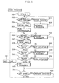
- Figure 6 is a flow chart illustrating the main program.
- step 202 a check is made to determine whether or not the output shaft 100 of the wiper motor 1 is at the housed-stop position. If said output shaft is not at the housed-stop position, the program continued to step 203, output ports Pl, P2 and P3 register (L, L, H) and reverse drive relay 23 is excited, whereupon wiper motor 1 commences low speed rotation in the reverse direction.
- step 203 the program enters overload detection subroutine 800.
- Said subroutine 800 shall be herein after described.
- the program is returned to step 202, and said output shaft 100 of the wiper motor 1 continues reverse rotation until arrival at said retracted- stop position.
- step 204 the program progresses from step 202 to step 204, whereupon output ports Pl, P2 and P3 register (L, L, L) and wiper motor 1 halts.
- step 204 if the wiper blade 110 is not housed at the retracted stop position A when power is input, wiper motor 1 is temporarily actuated in reverse rotation and the housing operation at the retracted stop position A is realized.
- the wiper blade 110 is moved temporarily to the retracted stop position A, regardless of the position of the wiper actuation switch 3, because the aforesaid process occurs without regard for the state (flexed or straight) of the crank arms 101, 102.
- step 205 wherein initialization of each flag is conducted.
- step 206 input port P10 is inspected to determine whether or not washer switch 71 is closed and washer motor 70 is under actuation. If said washer motor is under actuation, the program continues to washer interlock subroutine 700, while if said washer motor is not under actuation, the program continues to step 207.
- step 207 data in input ports P6 and P7 are read to determine the selection position of wiper actuation switch 3.
- wiper actuation switch read data is checked. If wiper actuation switch 3 position selection reads retracted stop actuation (OFF) position data (H, H), then the program continues from step 208 to off actuation sub routine 300; if selection reads intermittent actuation (INT) position data (H, L), then the program continues from step 209 to_intermittent actuation sub routine 400; if selection reads high speed actuation (HIGH) position data (L, H), then the program progresses from step 210 to high speed actuation sub routine 500; if the selection position data is none of the aforementioned three data configurations, the low speed actuation position is indicated by default and the program progresses from step 210 to low speed actuation sub routine 600.
- step 212 there is a pause for a prescribed period, for example just 0.1 seconds, then said step terminates and the program returns to step 206.
- steps 206 to 212 are repeated. Washer switch 71 and wiper actuation switch 3 selections are inspected at each prescribed period determined in step 212, and processing is realized corresponding to said selection positions.
- step 211 the selection position of wiper actuation switch 3 was the retracted stop (OFF) position. Nevertheless, the output shaft 100 of the wiper motor 1 is checked to see if it is actually at the retracted stop position, that is, it is checked to see if it is in a completely off state
- step 206 the program returns to step 206 via step 212 206, while if -said off state is not indicated, the return to step 206 occurs only after the running of overload detection subroutine 800.
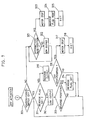
- Figure 7 is a flow chart illustrating details of off actuation sub routine.
- step 301 input port Pll is inspected to see whether or not it registers (H), housing-cancel switch 80 is set at the off position, and housing actuation is checked to see if it has been selected. If housing actuation is selected, the program continues to step 311, housing-cancel switch 80 is set at the on position, and if housing actuation override has been selected, the program continues to step 321.
- step 311 the reverse flag, which indicates that the first crank arm 101 has arrived at reverse position glC, is checked to see whether or not it has been set. Since initially, the reverse flag is reset, the program continues to step 312.
- step 312 the data (H, L, L) is output from output ports Pl, P2 and P3, forward drive relay 21 is excited, and wiper motor 1 begins normal low speed rotation.
- step 313 input ports P4 and P5 are checked for ( L , H) registration, and output shaft 100-is checked for arrival at reverse position glC. If input ports P4 and P5 register (L, H) and the reverse position has been reached, then the program continued to step 314 and the reverse flag is set. If such is not the case, nothing is realized and the program returns to step 311.
- step 314 When output shaft 100, namely crank arm 101, arrives at reverse position glC, the reverse flag is set in step 314 and the program returns to step 311. Said reverse flag is for the purpose of verification that the first crank arm 101 arrives at reverse position glC by normal rotation during housing actuation. Said flag is reset at the time selection of low speed and other actuations are realized. Said flag is set in flag initialization step 205.
- step 311 the program continues from step 311 to step 315 because the reverse flag is set.
- step 315 (L, L, H) data are output from output ports Pl, P2 and P3, reverse drive relay 23 is excited, and wiper motor 1 rotates at low speed in the reverse direction.
- step 316 input ports P4 and P5 are checked for (L, L) data, and wiper motor 1 output shaft 100 is checked for arrival at retracted stop position glA. If output shaft 100 has not reached retracted stop position glA, steps 311, 315 and 316 are repeated, wiper motor 1 reverse rotation continues.
- step 317 output ports Pl, P2 and P3 register (L, L, L), wiper motor 1 halts, and in step 318, the program returns to step 212 via step 211 of the main program.
- the first crank arm 101 temporarily rotates normally to reverse position glC.
- the second crank arm 102 reliably enters a straightened state, and wiper blade 110 is reliably housed at retracted stop positon A.
- step 301 When housing-cancel switch 80 is on and housing actuation override is selected, the program continues from step 301 to step 321.
- step 321 input ports P4 and P5 are checked for (H, L) data, and wiper motor 1 output shaft 100 is checked for arrival at intermittent pause position glB. If said output shaft has not reached intermittent pause position glB, the program continues to step 322, output ports Pl, P2 and P3 register (H, L, L), wiper motor 1 rotates normally at low speed, previous steps 321 and 322 are repeated, and the arrival of output shaft 100 at intermittent pause position glB is awaited.
- step 321 When said output shaft arrives at said intermittent pause position, the program progresses from step 321 to step 323, output ports Pl, P2 and P3 register (L, L, L), and wiper motor 1 halts, whereupon, in step 324, the reverse flag is reset, and the program returns to step 212 via step 211 of the main program from step 325.
- housing-cancel switch 80 When housing-cancel switch 80 is on, housing-stop actuation is overridden, and wiper blade 110 halts at intermittent pause position B. Moreover, when wiper blade 110 is housed at retracted stop position A, housing-cancel switch 80 is cut-over to on position, and wiper blade 110 rises to intermittent pause position B where is halts.
- the above described embodiment can be realized using one small sized contact switch with a change-over capacity to effectuate or override the housing function because it is controlled by microcomputer 5. Improvements and benefits include a simple and reliable control device circuit construction.
- a further improvement of said embodiment is the selection of housing function override by using the housing-cancel switch 80.
- Said system also has the capability to make selections automatically by employing a temperature sensor to monitor external conditions.
- step 209 of the main program When the intermittent actuation (INT) position is selected by wiper actuation switch 3, the program continues from step 209 of the main program to step 401 of the intermittent actuation (INT) sub routine 400.
- step 401 of Fig. 8 the pause actuation discrimination flag F10 is checked to see whether or not it is set.
- Pause actuation discrimination flag F10 is reset at each complete circuit of the wiping actuation, and is used to discriminate the initial state of the intermittent actuation process. Because said flag was initially reset in step 205 of the main program, the program now continues to step 402.
- step 402 various initial set values are determined, for example the fixed value N is set for intermit-counter C INT. Fixed value N will correspond to the maximum value for the intermittent pause period, for example 12 seconds. Then, in step 403, output ports Pl P2 and P3 output (H, L, L) data, whereupon wiper motor 1 commences low speed rotation. In step 404, pause actuation discrimination flag F10 is set, measuring time flag Fll and intermit-continuation flag F12 are reset, the intermittent process preparation terminates, and the program returns from step 405 to step 212 via step 211 of the main program.
- the fixed value N is set for intermit-counter C INT. Fixed value N will correspond to the maximum value for the intermittent pause period, for example 12 seconds.
- step 403 output ports Pl P2 and P3 output (H, L, L) data, whereupon wiper motor 1 commences low speed rotation.
- step 404 pause actuation discrimination flag F10 is set, measuring time flag Fll and intermit-continuation flag F
- step 212 after time-rest for a fixed period, for example 0.01 seconds, the program again enters step 401 of the intermittent actuation sub routine 400.
- step 406 pause actuation discrimination flag F10 has been set.
- step 406 measuring time flag Fll is checked to see whether or not it is set. Measuring time flag Fll discriminates among time periods for measuring vehicle speed.
- step 407 because said flag Fll was reset during the previous cycle.
- step 407 input port P9 is checked and a speed signal from vehicle speed detector 63 is input.
- step 408 input port P8 is checked and an oscillation signal from oscillation circuit 50 is input.
- step 409 the targeted intermittent pause period is calculated based upon the aforesaid signals.
- step 410 the result of said calculation is checked to see if a borrow signal has been generated. If said borrow signal has been generated, the program continues to step 411 and continuous-intermit flag F12 is set to allow continuous intermittent actuation. Thereafter, in step 412, the newly calculated data is input to the intermit-counter memory.
- Processing in steps 407 through 412 includes feedback on rise-up of various signals, for example rising transition values for the speed signals (input port P9) and the oscillation signals (input port P8), wherein the rise of each signal is detected and on each respective occurrence, in step 402, the set value (N) of intermit-counter C is reduced by a value of one (1) and a new intermit-counter C value is determined, and wherein flag 12 is set if the intermit-counter value generates a borrow signal. Furthermore, when no rise transition is detected in the speed signals or oscillation signals, nothing is realized and the program continues to step 413.
- step 413 the value stored in the memory of the time counter, wherein the measuring time is calculated, is reduced by a value of one (1).
- the time counter's initial value was set in step 402.
- step 414 the time counter value is checked for generation of a borrow signal. If a borrow signal has not been generated, the measuring time is completed and the program continues to step 415, whereupon flag Fll is set. Then from step 416 the program returns to step 212 via step 211 of the main program.
- the intermit-counter C value is varied in relation to the targeted intermittent pause period value which corresponds with the speed and variable resistor 59 set positions by merely repeating the fixed measuring period in the time counter.
- continuous intermit- flag F12 is set.
- measuring time flag Fll is set, and in the intermittent actuation sub routine of the subsequent cycle the program continues from step 406 to step 417.
- step 417 input ports P4 and P5 are checked for (H, L) data, and wiper motor 1 is checked to see if it has arrived at the intermittent pause position B. If said shaft has not reached the intermittent pause position, the program continues to step 418 wherein the previous steps 401, 406, 417 and 418 are repeated until the intermittent pause position has been reached. When said intermittent pause position has been reached, the program progresses from step 417 to step 419.
- step 419 the continuous-intermit discrimination flag F12 is checked to see if it is set.
- step 420 the program continues to step 420 because the intermittent pause period registers zero (0) and continuous actuation is realized. Ie step 420, the pause actuation discrimination flag F10 is reset and from step 421 the program continus to step 212 via step 211 of the main program. During the intermittent actuation sub routine of the subsequent cycle, the program continues from step 401 to pre-step 402, the aforesaid processes are repeated, and wiper motor 1 continues low speed rotation.
- step 422 output ports Pl, P2 and P3 register (L, L, L) data and wiper motor 1 halts.
- step 423 input port P8 is checked and the oscillation signal is input, whereupon in step 424, the remaining pause period is operated based upon said oscillation signal and targeted intermittent pause period value which was calculated in step 409 and stored in the intermit-counter C memory. This operation is conducted by means of subtracting a value of one (1) from the intermit-counter C every time a rising transition is detected in the oscillation signal or speed signal.
- step 425 the results of said operation are checked to see if a borrow signal has been generated, and if said borrow signal has not been generated, the program returns from step 428 to step 212 via step 211 of the main program. Therefore, in the intermittent actuation sub routine, the processes of steps 422 through 425 are repeated until the borrow signal is generated.
- step 426 there is a time-rest of only the minimum intermittent pause period Tl.
- step 427 intermittent actuation discrimination flag F10 is reset, and the program returns from step 428 to the main program.
- the aforesaid minimum intermittent pause period Tl may be fixed at between 0.1 and 1 seconds. Thus, the final intermittent pause period operation occurs in steps 419 through 428.
- the program continues to pre-step 402 level because the pause actuation discrimination flag F10 has been reset, the above described processing repeats from the beginning, thus controlling the wiper's intermittent actuation.
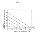
- Figure 9 is a special chart wherein is illustrated the parameters of the relationship of the intermittent pause period and vehicle speed as designated by the operation position of variable resistor 59.
- the minimum intermittent pause period Tl is set at one (1) second.
- the position of variable resistor 59 is pre-set so that the intermittent pause period is set at seven (7) seconds, then when vehicle speed increases from 0-60 km/h, the intermittent pause period continually will adjust accordingly from seven (7) to one (1) seconds. Under conditions in which vehicle speed exceeds 60 km/h, there is an automatic conversion to continuous low speed actuation.
- the embodiment of the present system herein above described possesses improvements which include a control system wherein the circuit construction is uncomplicated due to the utilization of microcomputer 5 as a control means.
- a further improvement includes a simple circuit construction wherein several input ports are not required, where only two input ports are installed which are used for the purpose of varying the intermittent pause period, namely input port P8, for input of the oscillation signal and input port P9, for input of the vehicle speed signal.
- Improvements relating to furnctions include the capacity to convert automatically to continuous actuation when vehicle speed increases and the intermittent pause period shortens.
- a further improvement includes the capacity to allow the operator to freely vary the intermittent pause period by means of variable resistor 59 operation even when said vehicle is under speed-sensitive actuation.
- This embodiment of the present device possesses improvements which include a means for setting a minimum intermittent pause period, thus preventing sudden repetition of on/off actuation due to an extremely short intermittent pause period, and thus also preventing excessive loads on wiper motor drive circuit 6 and wiper motor 1.
- a still further improvement includes improved comfort for the vehicle operator because the present device possesses the capability to precisely partition the wiper's intermittent pause time and the continuous actuation time.
- An additional improvement of the present embodiment includes the capacity for the vehicle operator to easily override the speed-sensitive function by means of the speed-auto switch.
- Fig. 10 is a flow chart detailing the high-speed (HIGH) acutuation sub routine 500.
- step 501 of the high-speed (HIGH) operation sub routine 500 IX step 501, with output ports Pl, P2 and P3 at H, H and L, respectively, the forward drive relay 21 and high-speed changeover relay 22 are magnetized; the wiper motor 1 is made to turn at high speed in the forward -direction, and in the next step 502 the reverse flag is set before moving from step 503 back to step 212 via step 211 of the main program. Then steps 501 through 503 are repeated, and the wiper motor 1 is actuated at high speed.
- step 210 of the main program we proceed from step 210 of the main program to the step 601 of the low-speed (LOW) actuation sub routine 600 shown in Fig. 11.
- step 601 with output ports Pl, P2 and P3.at H, L and L, respectively, only the forward drive relay 21 is magnetized, and the wiper motor 1 is actuated at low speed in the forward direction; then, in step 602, the reverse flag is reset and we move back to step 212 via step 211 of the main program from step 603. Thereafter, step 601 and 603 are repeated, and the wiper motor 1 is run at low speed.
- step 206 of the main program As washer switch 71 is operated, the program progresses from step 206 of the main program to step 701 of washer interlock sub routine 700.
- step 701 of Fig. 12 the interlock flag is inspected to determine whether or not it has been set.
- the washer interlock flag is set when any actuation mode is actuated, other than the washer interlock actuation mode. Since said interlock flag is initially set, the program continues to step 702.
- step 702 a fixed value is set in the timer-counter. Said fixed value is set in the region of 0.5 seconds.
- step 703 the interlock flag is reset, and in step 704 a value of one (1) is subtracted from the timer-counter, and in step 705 the timer-counter value is inspected to determine whether or not it is a zero (0) value.
- step 212 of the main program returns from step 706 to step 212 via step 211 of the main program. Thereafter, until the timer-counter value reaches a zero (0) value, steps 211, 212, 206, and steps 701, 704, 705 and 706 are repeated sequentially.
- steps 211, 212, 206, and steps 701, 704, 705 and 706 are repeated sequentially.
- Each time step 212 of the main program is passed through there is a time-rest during which nothing is realized, for example if there is a fixed period time-rest of only 0.1 seconds and if the fixed value set in step 702 is five (5), then a time-rest period of approximately 0.5 seconds will be conducted during which no actuation will be realized.
- Said time-rest period is for the purpose of initiating wiper actuation after washer motor 70 is actuated and washing solution is actually discharged. Furthermore, when washer switch 71 is erroneously operated at extremely short periods, said time-rest function prevents wiper actuation.
- step 707 wiper actuation switch 3 is inspected to determine whether or not the selected position is the high speed actuation (HIGH) position. If high speed actuation has been selected, the program progresses to step 708 in order to continue wiping actuation under the same conditions. Whereupon, output ports Pl, P2 and P3 register (H, H, L) data and forward drive relay 21 and high speed changeover relay 22 are excited, and wiper motor 1 commences high speed rotation in the normal direction.
- output ports Pl, P2 and P3 register (H, H, L) data and forward drive relay 21 and high speed changeover relay 22 are excited, and wiper motor 1 commences high speed rotation in the normal direction.
- step 709 If an actuation mode other than high speed actuation is selected, the program continues to step 709, and output ports Pl, P2 and P3 register (H, L, L) data, whereupon wiper motor 1 commences low speed actuation. Thus, wiper blade 110 is raised from retracted stop position A and wiper actuation is initiated.
- step 710 a prescribed value, for example the value three (3), is set in the interlock counter which determines the wiper's wiping frequency during the washer interlock actuation period.
- a prescribed value for example the value three (3)
- step 711 while input ports P4 and P5 are inspected, via wiper motor position detector 2, to determine whether or not they register (L, H) data, the arrival of wiper motor 1 output shaft 100 at reverse position glC is awaited.
- step 712 the interlock value is reduced by a value of one (1).
- step 713 the interlock counter is inspected to determine whether or not it is a zero (0) value.
- step 714 If said value is not a zero (0) value, the program continues to step 714 where, as input ports P4 and P5 are inspected to determine whether or not they register (H, L) data, the arrival of wiper motor 1 output shaft 100 at intermittent pause position glB is awaited. When said output shaft reaches said intermittent pause position, the program again returns to step 711.
- steps 711 to 714 are repeated sequentially, passage of wiper motor 1 output shaft 100 through reverse position glC and intermittent pause position glB is verified, and the number of wiping movements completed by the wiper are tabulated.
- the program continues from step 713 to step 715.
- step 715 the reverse flag is reset at the retracted stop position, and in step 716 a return is made to step 212 via step 211 of the main program. On this occasion, wiper motor 1 continued low speed rotation.
- Figure 13 is a flow chart illustrating details of overload detection subroutine 800.
- step 801 the S seconds timer is initially set. This prescribed time period of S seconds is fixed at a value greater than is necessary for the time it takes wiper motor 1 to complete one revolution under normal load conditions.
- step 802 a check is conducted to determine whether or not the wiper motor 1 output shaft 100 has made one revolution. If said output shaft has made one revolution, the program returns from step 803 to the prescribed step of the main program, while if said output shaft has not made one revolution, the program continues to step 804. Whether or not one revolution has been completed, a check is made, by means of position detector 2, to determine if said output shaft has travelled from the intermittent pause position through the reverse position and returned to the intermittent pause position.
- step 804 a check is made to determine if time has expired for the S seconds timer and if a timer borrow signal has been generated. If said prescribed time period has not elapsed, the program returns from step 805 to the main program, while if said period has elapsed, the program continues to pre-step 806.
- checks are made to determine if the wiper motor 1 output shaft 100 completes one revolution within the prescribed S seconds. If one revolution has been completed by said output shaft, a return is made to the main program while in said state, while if one revolution has not been completed, the program continues the process of pre-step 806 overload time analysis.
- step 806 output ports Pl, P2 and P3 output (L, L, L) data, relays 21, 22 and 23 all completely shut off, and current to wiper motor 1 is cut off.
- step 807 output port P15 registers a high level (H) and the warning light 90 is illuminated.
- step 809 output port P8 registers (L) and the warning light 90 is extinguished, whereupon the program returns from step 810 to the main program, the recovery period is completed, and thereafter, operation returns to normal.
- step 821 After entering said overload detection subroutine, in initial step 821, input ports P4 and P5 are checked and the two bit motor position data from position detector 2 are read. Thereupon, in step 822, the data stored in memory P concerning motor position during the previous cycle and motor position date M of the current cycle are checked for matching. If said data are not matched, the program continues to step 823 because the wiper motor 1 output shaft 100 rotates to the next position. L 'step 823, a prescribed value is set in timer-counter C, and in step 824, the motor position data M of the current cycle is entered into memory P. Thereupon, in step 825, a time-rest is initiated for a prescribed period, for example 0.1 seconds, and the program returns from step 826 to the main program.
- step 822 if the data stored in memory P concerning motor position during the previous cycle and motor position data M of the current cycle are matched, the program continues to step 827 because the wiper motor 1 output shaft 100 does not yet rotate to the next position.
- step 827 a value of one (1) is subtracted from timer-counter C.
- step 828 timer-counter C is checked for a zero (0) value.
- step 824 If said timer-counter does not register a zero (0) value, the program continues to step 824 because the prescribed period has not elapsed, while if said timer-counter does register a zero (0) value, the motor speed decreases due to the wiper motor 1 output shaft 100 staying in the same position past the prescribed time period, whereupon said wiper motor 1 is determined to be under an overload, and the program continues to the prestep 829 overload process.
- the processes occurring in steps 829 to 833 are identical to the processes occurring in steps 806 and 810, illustrated in Fig. 13, wherein during a prescribed time period (y seconds), wiper motor 1 current is cut, and the process of illuminating the warning light 90 is actuated.
- the wiper control system of the present device by employing the aforesaid construction, has the beneficial effect of protecting the wiper motor from overload without attachment to said wiper motor of a bimetal circuit breaker.
Landscapes
- Engineering & Computer Science (AREA)
- Automation & Control Theory (AREA)
- Water Supply & Treatment (AREA)
- Mechanical Engineering (AREA)
- Control Of Direct Current Motors (AREA)
Applications Claiming Priority (10)
| Application Number | Priority Date | Filing Date | Title |
|---|---|---|---|
| JP197192/84U | 1984-12-26 | ||
| JP19719284U JPH0311083Y2 (fr) | 1984-12-26 | 1984-12-26 | |
| JP555285U JPH0349971Y2 (fr) | 1985-01-20 | 1985-01-20 | |
| JP5553/85U | 1985-01-20 | ||
| JP5554/85U | 1985-01-20 | ||
| JP555185U JPS61122149U (fr) | 1985-01-20 | 1985-01-20 | |
| JP555385U JPS61122148U (fr) | 1985-01-20 | 1985-01-20 | |
| JP5552/85U | 1985-01-20 | ||
| JP5551/85U | 1985-01-20 | ||
| JP555485U JPS61122147U (fr) | 1985-01-20 | 1985-01-20 |
Publications (3)
| Publication Number | Publication Date |
|---|---|
| EP0186178A2 true EP0186178A2 (fr) | 1986-07-02 |
| EP0186178A3 EP0186178A3 (en) | 1987-05-20 |
| EP0186178B1 EP0186178B1 (fr) | 1989-07-19 |
Family
ID=27518614
Family Applications (1)
| Application Number | Title | Priority Date | Filing Date |
|---|---|---|---|
| EP85116477A Expired EP0186178B1 (fr) | 1984-12-26 | 1985-12-23 | Système d'essuie-glace caché |
Country Status (2)
| Country | Link |
|---|---|
| EP (1) | EP0186178B1 (fr) |
| DE (2) | DE186178T1 (fr) |
Cited By (2)
| Publication number | Priority date | Publication date | Assignee | Title |
|---|---|---|---|---|
| DE4109318A1 (de) * | 1991-03-21 | 1992-09-24 | Man Nutzfahrzeuge Ag | Steuereinrichtung fuer den scheibenwischbetrieb eines kraftfahrzeuges |
| CN109980846A (zh) * | 2018-12-24 | 2019-07-05 | 贵阳万江航空机电有限公司 | 一种可以控制汽车洗涤系统喷水时机的雨刮电机 |
Families Citing this family (1)
| Publication number | Priority date | Publication date | Assignee | Title |
|---|---|---|---|---|
| DE4304063C2 (de) * | 1993-02-11 | 1998-02-05 | Telefunken Microelectron | Verfahren zum Betrieb eines Scheibenwischermotors |
Family Cites Families (8)
| Publication number | Priority date | Publication date | Assignee | Title |
|---|---|---|---|---|
| US3120673A (en) * | 1962-05-14 | 1964-02-11 | Gen Motors Corp | Concealed windshield wiper mechanism |
| DE2851727A1 (de) * | 1978-11-30 | 1980-06-26 | Rau Swf Autozubehoer | Schaltanordnung fuer einen aus einer spannungsquelle gespeisten drehrichtungsumkehrbaren elektrischen antriebsmotor |
| GB2072879B (en) * | 1980-03-22 | 1983-06-22 | Landmass Ltd | Windscreen wiper control |
| FR2515588A1 (fr) * | 1981-10-30 | 1983-05-06 | Raes Marc | Temporisateur d'essuie-glace a reglage automatique selon la vitesse |
| FR2518471A1 (fr) * | 1981-12-21 | 1983-06-24 | Renault | Procede et dispositif de commande automatique de la cadence de fonctionnement d'un essuie-vitre, notamment pour vehicule automobile |
| DE3327373C1 (de) * | 1983-07-29 | 1984-12-20 | Leopold Kostal GmbH & Co KG, 5880 Lüdenscheid | Scheibenwischeinrichtung für Kraftfahrzeuge |
| US4492904A (en) * | 1983-09-01 | 1985-01-08 | General Motors Corporation | Windshield wiper system with touch control |
| US4673853A (en) * | 1985-01-18 | 1987-06-16 | Asmo Co., Ltd. | Concealed wiper system |
-
1985
- 1985-12-23 DE DE1985116477 patent/DE186178T1/de active Pending
- 1985-12-23 EP EP85116477A patent/EP0186178B1/fr not_active Expired
- 1985-12-23 DE DE8585116477T patent/DE3571585D1/de not_active Expired
Cited By (3)
| Publication number | Priority date | Publication date | Assignee | Title |
|---|---|---|---|---|
| DE4109318A1 (de) * | 1991-03-21 | 1992-09-24 | Man Nutzfahrzeuge Ag | Steuereinrichtung fuer den scheibenwischbetrieb eines kraftfahrzeuges |
| CN109980846A (zh) * | 2018-12-24 | 2019-07-05 | 贵阳万江航空机电有限公司 | 一种可以控制汽车洗涤系统喷水时机的雨刮电机 |
| CN109980846B (zh) * | 2018-12-24 | 2024-06-11 | 贵阳万江航空机电有限公司 | 一种可以控制汽车洗涤系统喷水时机的雨刮电机 |
Also Published As
| Publication number | Publication date |
|---|---|
| EP0186178B1 (fr) | 1989-07-19 |
| DE186178T1 (de) | 1986-12-18 |
| DE3571585D1 (en) | 1989-08-24 |
| EP0186178A3 (en) | 1987-05-20 |
Similar Documents
| Publication | Publication Date | Title |
|---|---|---|
| US4689535A (en) | Concealed wiper system | |
| EP0598862B1 (fr) | Interface pour la commande d'essuie-glace sensible a l'humidite | |
| US4348726A (en) | Method of controlling automobile equipment and control apparatus | |
| US4336482A (en) | Rear window wiper motor control | |
| EP0188226B1 (fr) | Système d'essuie-glace caché | |
| GB2049234A (en) | Windscreen wiper installation | |
| JPS604678B2 (ja) | 1電源で給電される可逆電動機用回路装置 | |
| EP0082593B1 (fr) | Dispositif d'entraînement d'essuie-glaces pour un véhicule automobile | |
| US4866359A (en) | Apparatus to provide temperature controlled windshield wiper positions for motor vehicles | |
| EP1057702B1 (fr) | Dispositif de contrôle d'essuie-glace | |
| EP0186178A2 (fr) | Système d'essuie-glace caché | |
| US4999550A (en) | Automatic rear wiper control | |
| US20020008486A1 (en) | Wiper control Apparatus | |
| US6219598B1 (en) | Automotive controller maintaining operation of controlled device when a microcomputer overruns and cannot be reset | |
| EP1176067B1 (fr) | Dispositif de contrôle d'essuie-glace | |
| JPS61130654A (ja) | 自動変速制御方法 | |
| US4692677A (en) | Windshield wiper system | |
| US4286200A (en) | Universal intermittent windshield wiper circuit | |
| US20020008485A1 (en) | Wiper control apparatus | |
| JP2582618Y2 (ja) | オートワイパ装置 | |
| KR19980043313A (ko) | 자동차 윈드실드 와이퍼 속도 자동제어장치 및 그 제어방법 | |
| KR940000995Y1 (ko) | 자동차 윈도우 브러시 회전속도 제어회로 | |
| KR960013248B1 (ko) | 자동차후방감시경의 작동장치 | |
| JPH0411889Y2 (fr) | ||
| JPH054453Y2 (fr) |
Legal Events
| Date | Code | Title | Description |
|---|---|---|---|
| PUAI | Public reference made under article 153(3) epc to a published international application that has entered the european phase |
Free format text: ORIGINAL CODE: 0009012 |
|
| AK | Designated contracting states |
Kind code of ref document: A2 Designated state(s): DE FR GB |
|
| 17P | Request for examination filed |
Effective date: 19860730 |
|
| EL | Fr: translation of claims filed | ||
| DET | De: translation of patent claims | ||
| PUAL | Search report despatched |
Free format text: ORIGINAL CODE: 0009013 |
|
| AK | Designated contracting states |
Kind code of ref document: A3 Designated state(s): DE FR GB |
|
| 17Q | First examination report despatched |
Effective date: 19880311 |
|
| GRAA | (expected) grant |
Free format text: ORIGINAL CODE: 0009210 |
|
| AK | Designated contracting states |
Kind code of ref document: B1 Designated state(s): DE FR GB |
|
| REF | Corresponds to: |
Ref document number: 3571585 Country of ref document: DE Date of ref document: 19890824 |
|
| ET | Fr: translation filed | ||
| PLBE | No opposition filed within time limit |
Free format text: ORIGINAL CODE: 0009261 |
|
| STAA | Information on the status of an ep patent application or granted ep patent |
Free format text: STATUS: NO OPPOSITION FILED WITHIN TIME LIMIT |
|
| 26N | No opposition filed | ||
| PGFP | Annual fee paid to national office [announced via postgrant information from national office to epo] |
Ref country code: FR Payment date: 19961211 Year of fee payment: 12 |
|
| PGFP | Annual fee paid to national office [announced via postgrant information from national office to epo] |
Ref country code: GB Payment date: 19961216 Year of fee payment: 12 |
|
| PGFP | Annual fee paid to national office [announced via postgrant information from national office to epo] |
Ref country code: DE Payment date: 19961231 Year of fee payment: 12 |
|
| PG25 | Lapsed in a contracting state [announced via postgrant information from national office to epo] |
Ref country code: GB Free format text: LAPSE BECAUSE OF NON-PAYMENT OF DUE FEES Effective date: 19971223 |
|
| PG25 | Lapsed in a contracting state [announced via postgrant information from national office to epo] |
Ref country code: FR Free format text: THE PATENT HAS BEEN ANNULLED BY A DECISION OF A NATIONAL AUTHORITY Effective date: 19971231 |
|
| GBPC | Gb: european patent ceased through non-payment of renewal fee |
Effective date: 19971223 |
|
| PG25 | Lapsed in a contracting state [announced via postgrant information from national office to epo] |
Ref country code: DE Free format text: LAPSE BECAUSE OF NON-PAYMENT OF DUE FEES Effective date: 19980901 |
|
| REG | Reference to a national code |
Ref country code: FR Ref legal event code: ST |