EP0186198A2 - System und Verfahren zur Positionsbestimmung eines Empfängers aus den von Satelliten ausgestrahlten Signalen. - Google Patents
System und Verfahren zur Positionsbestimmung eines Empfängers aus den von Satelliten ausgestrahlten Signalen. Download PDFInfo
- Publication number
- EP0186198A2 EP0186198A2 EP85116571A EP85116571A EP0186198A2 EP 0186198 A2 EP0186198 A2 EP 0186198A2 EP 85116571 A EP85116571 A EP 85116571A EP 85116571 A EP85116571 A EP 85116571A EP 0186198 A2 EP0186198 A2 EP 0186198A2
- Authority
- EP
- European Patent Office
- Prior art keywords
- signal
- spread spectrum
- satellite
- phase
- error
- Prior art date
- Legal status (The legal status is an assumption and is not a legal conclusion. Google has not performed a legal analysis and makes no representation as to the accuracy of the status listed.)
- Granted
Links
Images
Classifications
-
- G—PHYSICS
- G01—MEASURING; TESTING
- G01S—RADIO DIRECTION-FINDING; RADIO NAVIGATION; DETERMINING DISTANCE OR VELOCITY BY USE OF RADIO WAVES; LOCATING OR PRESENCE-DETECTING BY USE OF THE REFLECTION OR RERADIATION OF RADIO WAVES; ANALOGOUS ARRANGEMENTS USING OTHER WAVES
- G01S19/00—Satellite radio beacon positioning systems; Determining position, velocity or attitude using signals transmitted by such systems
- G01S19/01—Satellite radio beacon positioning systems transmitting time-stamped messages, e.g. GPS [Global Positioning System], GLONASS [Global Orbiting Navigation Satellite System] or GALILEO
- G01S19/13—Receivers
- G01S19/35—Constructional details or hardware or software details of the signal processing chain
- G01S19/37—Hardware or software details of the signal processing chain
-
- G—PHYSICS
- G01—MEASURING; TESTING
- G01S—RADIO DIRECTION-FINDING; RADIO NAVIGATION; DETERMINING DISTANCE OR VELOCITY BY USE OF RADIO WAVES; LOCATING OR PRESENCE-DETECTING BY USE OF THE REFLECTION OR RERADIATION OF RADIO WAVES; ANALOGOUS ARRANGEMENTS USING OTHER WAVES
- G01S19/00—Satellite radio beacon positioning systems; Determining position, velocity or attitude using signals transmitted by such systems
- G01S19/01—Satellite radio beacon positioning systems transmitting time-stamped messages, e.g. GPS [Global Positioning System], GLONASS [Global Orbiting Navigation Satellite System] or GALILEO
- G01S19/13—Receivers
- G01S19/23—Testing, monitoring, correcting or calibrating of receiver elements
- G01S19/235—Calibration of receiver components
-
- G—PHYSICS
- G01—MEASURING; TESTING
- G01S—RADIO DIRECTION-FINDING; RADIO NAVIGATION; DETERMINING DISTANCE OR VELOCITY BY USE OF RADIO WAVES; LOCATING OR PRESENCE-DETECTING BY USE OF THE REFLECTION OR RERADIATION OF RADIO WAVES; ANALOGOUS ARRANGEMENTS USING OTHER WAVES
- G01S19/00—Satellite radio beacon positioning systems; Determining position, velocity or attitude using signals transmitted by such systems
- G01S19/01—Satellite radio beacon positioning systems transmitting time-stamped messages, e.g. GPS [Global Positioning System], GLONASS [Global Orbiting Navigation Satellite System] or GALILEO
- G01S19/13—Receivers
- G01S19/24—Acquisition or tracking or demodulation of signals transmitted by the system
- G01S19/30—Acquisition or tracking or demodulation of signals transmitted by the system code related
Definitions
- the present invention relates generally to a receiver adapted to receive a spectrum-diffusion signal in Global Positioning System (GPS /NAVSTAR), which receiver will be hereafter referred to as a "GPS receiver”. More specifically, the invention relates to a circuit for correcting the phase shift of a locally derived Gold code relative to the phase of a Gold code sequence received from(a) satellite(s).
- GPS /NAVSTAR Global Positioning System
- the invention relates to a circuit for correcting the phase shift of a locally derived Gold code relative to the phase of a Gold code sequence received from(a) satellite(s).
- NAVSTAR Global Positioning System wherein a constellation of eighteen orbiting satellites transmit pseudo-ranrom ranging signals (hereafter referred to as "PRN signals") from which users with appropriate equipment can obtain three-dimentional location. velocity and timing information anywhere on or near the surface of the Earth.
- PRN signals pseudo-ranrom ranging signals
- the details of the NAVSTAR/GPS are given in "NAVIGATION", Journal of the Institute of Navigation. Volume 25. Number 2, December. 1978.
- the eighteen satellites will be deployed in circular 10, 90 0-nautical-mile orbits in three mutually-inclined planes.
- a minimum of four satellites will be in twelve-hours orbits and the position of each satellite at any time will be precisely known.
- the longitude, latitude and altitude of any point close to Earth, with respect of the center of the Earth can be calculated from the propagation times of electromagnetic signals from four of the satellites to that point.
- a signal about a single center frequency from each visible satellite will be received by a user terminal at a point close to Earth to measure propagation times of the electromagnetic signals transmitted by the satellites.
- the satellites from which the signals originate are identified by modulating the signal transmitted from each satellite with pseudo-random coded signals.
- the GPS system will operate in two modes simultaneouly. In one mode, referred to as the clear-acquisition (C/A) mode.
- the PRN signal is a Gold code sequence that is repeated once every millisecond to enable the position of the receiver responsive to the signal transmitted from four of the satellites to be determined to an accuracy of 1 00 meters.
- pseudo-random codes are transmitted with sequences that are 7-days long, enabling the user terminal position to be determined to an accuracy of better than 10 meters.
- Gold code' generally means the PRN signal used in C/A mode but may also refers the pseudo-random code used in P mode.
- the receiver When computing the user terminal position, the receiver will operate in three modes, viz, signal acquisition, signal tracking and position fixing.
- the acquisition mode the receiver must know, approximately, its location and have available a recent version of the GPS almanac.
- Doppler estimates must then be computed for the subset of GPS satellites with the best geometry, i.e., the four satellites with the greatest elevation, typically above 20° as observed by the given terminal. This leaves the GPS demodulator with a GPS carrier frequency uncertainty of several hundred hertz.
- the receiver also contains a number of different Gold code reference sources corresponding to the number of satellites in the constellation.
- the locally derived code and carrier references are cross-correlated with received GPS signals over one or more Gold code sequence intervals.
- the receiver shifts the phase of the locally derived Gold code sequence on a chip-by-chip basis and within each chip in 0.5-1.0 microsecond steps, spanning one millisecond code periods for the C/A code until the maximum cross-correlation is obtained.
- the chipping rate of a pseudo-random sequence is the rate at which the individual pulses in the sequence are derived and therefore is equal to the code repetition rate divided by the number of chips in the code. Each pulse in the code is referred to as a chip.
- code delay is tracked continuously and an aligned or "punctual" code stream generated. This is implemented with either a delay lock loop or by means of the tau-dither technique. In either case, the result is a continuously tracked code generator with delay error on the order of 0. 1 microsecond.
- initial Doppler uncertainty must be further reduced. This is done by stepping the frequency synthesizer and measuring the correlator output. Once the Doppler uncertainty is reduced to 10-2 0 Hz, the carrier phase and the raw GPS data messages are recovered using a Costas loop and the aforementioned punctual code.
- Position accuracy may be obtained to about 100 meters.
- This data processing requires storage in the terminal of ephemeris parameters, updated hourly, together with a software model for the GPS satellite orbits, to allow computation in real time of satellite coordinates for correspondence with time of arrival of GPS satellite-generated pseudo-range data.
- the Gold code sequence transmitted by the different satellites are arranged so that a maximum cross-correlation product between any two of them is about 65, whereas the autocorrelation produce of an internal Gold code generator which produces the local Gold code sequence and the Gold code sequence transmitted from one of the satellite is 1023.
- the correlation value is defined, for this purpose, as the number of identical bits in a 1023-bit epoch of a Gold code sequence.
- the GPS receivers use conventional delay-locked loops to adjust the phase of the local Gold code generator.
- a delay-locked loop comprises a correlation circuit, a phase error derivation circuit, a voltage-controlled oscillator and the local Gold code generator.
- the correlation circuit produces a correlation output when the local Gold code sequence from the local Gold code generator correlates well with the Gold code sequence from the satellite.
- the phase error derivation circuit responds to this correlation output by outputting a phase error signal.
- the voltage-controlled oscillator is controlled by a clock signal with a variable oscillation frequency related to the phase error signal. This holds the two Gold codes in phase.
- the controlling oscillator in a loop which controls the local Gold code generator based on the phase error between the Gold code sequence received from the satellite and the local Gold code derived by the local Gold code generator which loop will be referred to as the "PN-locking loop"
- PN-locking loop is made up of analog circuitry, such as a voltage-controlled oscillator. it prevents full integration of the circuitry of the GPS receiver. Therefore, it is desired to implement the PN-locking loop solely in digital circuitry.
- a numerically controlled oscillator (NCO) may be employed.
- NCO numerically controlled oscillator
- delicate control of the local Gold code generator would be impossible. For instance, assuming the oscillation frequency of the NCO is f. phase control at a precision finer than 1/f s would be impossible.
- Another and more specific object of the present invention is to provide a GPS receiver employing NCO's in the PN-locking loop for controlling the phase of a local Gold code generator precisely.
- a GPS receiver in accordance with the present invention, comprises a phase-error derivation circuit which derives the average phase error over a predetermined period.
- the phase-error derivation circuit sends an average phase difference signal to a numerically controlled oscillator to control its clock rate.
- the present invention makes application of digital circuitry to the delay locked loop in the GPS receiver possible.
- a receiver system for deriving the position of a receiver station from spectral diffusion signals broadcast by satellites, comprising means for receiving the spread spectrum signal and a repeating pulse epoch having the same frequency with the spread spectrum signal, means, installed in the receiver system, for generating a signal essentially matching the spread spectrum signal from the satellite and containing pulse epochs at intervals essentially matching those of the signal from the satellite, means for comparing the spread spectrum signals from the satellite with the internally generated signal and producing a correlation signal when correlation therebetween is established, means, responsive to the correlation signal from the correlating means, for deriving the average phase error between the spread spectrum signal from the satellite and the internally generated signal over predetermined periods of times , and producing an average phase-error signal, means, responsive to the average phase error signal, for controlling the internal spread spectrum signal generating means to adjust the phase of the internally generated spread spectrum signal so as to reduce the phase error, and means for deriving a basic propagation time value of the spread spectrum signal from the satellite relative to the internally generated
- the means for controlling the internal spread spectrum signal generating means comprises a digital circuit. Also, the means for deriving the average phase-error comprises a digital circuit.
- the means for controlling the internal spread spectrum signal" generating means comprises a numerically controlled oscillator.
- the predetermined period of time match the epoch intervals of the spread spectrum signals.
- the receiver system further comprises a clock generator and the means for controlling the internal spread spectrum signal generating means controls the pulse frequency of a clock signal generated by the clock generator for controlling the phase of the internally generated spread spectrum signal.
- a process for deriving the position of a receiver station from a spread spectrum signal transmitted by a satellite comprises the steps of:
- the step of controlling the phase of the internal spread spectrum signal is performed by means of a digital circuit, and the step of deriving the average phase-error is performed by'a digital circuit.
- the step of controlling the phase of the internal spread spectrum signal is performed by a numerically controlled oscillator.
- the predetermined period of time match the epoch intervals of the spread spectrum signals.
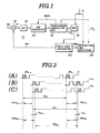
- a GPS receiver 10 has a looped circuit including a correlation circuit 12, a band-pass filter 14, a phase-error derivation circuit 16, a numerically controlled oscillator 18 and an internal or local Gold code generator 20.
- the local Gold code generator 20 generates a local Gold code sequence Sp made up of repeating epochs at known intervals, which local Gold code sequence will be hereafter referred to as the "local code”.
- the local Gold code sequence matches a Gold code sequence S IN received from a satellite, which will be hereafter referred to as the "satellite code”.
- the correlation circuit 12 comprises a multiplier which receives both the satellite code S IN and the local code S PN for correlation thereof.
- the correlation circuit 12 produces a correlation output S when correlation between the satellite code and the local code is established.
- the phase-error derivation circuit 16 responds to the correlation output S 1 from the correlation circuit 12 by deriving the magnitude ⁇ of phase error between the satellite code S IN and the local code S PN .
- the phase-error derivation circuit 16 outputs a phase-error signal S ⁇ to the numerically controlled oscillator 18.
- the oscillation frequency f s of a clock signal generated the numerically controlled oscillator 18 is controlled on the basis of the phase-error signal.
- the clock controls the phase of the local Gold code generator 20. This holds the satellite code S IN and the local code SpN in phase.
- the epoch of the satellite code which repeats at regular intervals, is sent to a propagation time measuring circuit 22.
- the propagation time measuring circuit 22 derives a propagation time value based on the delay of the epoch of the satellite code relative to the epoch of the local code.
- the phase-error derivation circuit 16 is digital. Therefore, in order to make the correlation output S of the correlation circuit 12 transmitted through the band-pass filter 14 applicable to the digital phase-error derivation circuit 16, an analog-to-digital (A/D) converter 24 is installed between the band-pass filter 14 and the phase-error derivation circuit 16.
- A/D analog-to-digital
- the phase-error derivation circuit 16 derives a value indicative of the phase error A0 between the satellite code S IN and the local code S PN .
- the phase-error derivation circuit 16 integrates the phase-error indicative values over one epoch cycle TE2N of the satellite code to derive an average phase error value ⁇ N and produce a corresponding average phase-error signal S ⁇ .
- the phase-error derivation circuit 16 sends the average phase-error signal S A0 to the numerically controlled oscillator 18.
- Derivation circuit 16 has an internal clock generator 26 which outputs a sampling clock SCLK to the A/D converter 24.
- the frequency of the sampling clock SCLK is selected to be sufficiently high to enable the A/D converter 24 to convert the correlation output S of the correlation circuit 12 into a digital signal.
- the numerically controlled oscillator 18 receives a clock f s which has a frequency of 40 nsec, for example.
- the numerically controlled oscillator 18 derives a pulse rate based on the average phase-error signal S ⁇ and produces a clock S CL with the derived pulse rate.
- the phase of the local code S PN produced by generator 20 is controlled by the clock S CL from the numerically controlled oscillator 18.
- the local Gold code generator 20 produces each epoch EP i (EP N-1 , EP N .7) of the local code. Upon generating each epoch, the local Gold code generator 20 outputs a timing signal TIM to the propagation measuring circuit 22.
- the propagation time measuring circuit 22 also receives the clock f s , the phase-error signal S ⁇ and the timing signal TIM and derives the propagation time at every occurence of the epoch, i.e. every 1 msec.
- Fig. 2(A) shows the -transmission timing of the Gold code S in the satellite.
- the Gold code S is made up of epochs EP N-1 , EP N ... repeating at known intervals, e.g. 1 msec.
- the satellite code S IN (Fig. 2(B) is received by the GPS receiver 10 after a propagation time TPD1 N-1 , TPD1 N ...
- the GPS receiver 10 controls the phase of the local Gold code generator 20 so that the phase of the local code Sp N (Fig. 2(c) approaches the phase of the satellite code S PN to the extent possible.
- the phase of the local code S PN cannot be adjusted relative to the satellite code S IN beyond the resolution of the clock frequency f s . Therefore, the local code S PN is still subject to a slight phase error ⁇ N-1 , ⁇ N relative to the satellite code.
- phase errors ⁇ N-1 , ⁇ N at the measuring points N-1 and N at which epochs in the sattelite code start can be expressed by the following equation:
- TE 1 is the interval between the epochs EP N-1 and EP N of the satellite code S IN ;
- TE 2 is the interval between the epochs EP N-1 and EP N of the local code Sp N .
- phase errors vary linearly. Since the interval TE 0 between the epochs EP N-1 and EPN of the Gold code S generated by the satellite is 1 msec., the average phase-error ⁇ N can be expressed as:
- phase-error ⁇ N can be calculated by:
- the actual propagation time TPD 1 can be obtained from the following equation:
- the propagation time deriving circuit 24 solves formula (4) in order to derive the actual propagation time TPD 1N .
- the propagation time deriving circuit 24 counts the clock pulse f s from the known timing at which the epoch EP N is transmitted from the satellite until the timing signal TIM from the local Gold code generator 20, in order to measure the propagation time TPD 2N .
- the propagation time deriving circuit 24 counts the clock pulse f s in response to the timing signal TIM to derive the epoch cycle TE 2N .
- the timing signal TIM can be produced in synchronism with timing of the clock f s . Therefore, there cannot be an error between the propagation time TPD 2N and the epoch cycle TE2N.
- the propagation time deriving circuit 24 also receives the average phase-error signal S ⁇ from the phase-error derivation, circuit 16, as set forth above.
- the epoch cycle TE may be regarded as being constant.
- an accurate propagation time value TPD 1N can be obtained by solving formula ( 4 ).
- the numerically controlled oscillator 18 is responsive to the average phase-error signal S ⁇ from the phase-error derivation circuit 1 6 to adjust its the pulse frequency so that the local code S PN and the satellite code S IN can be held in phase.
- the preferred embodiment of the GPS receiver makes the accuracy of the derived propagation time value TPD 1N substantially higher than ⁇ 1/f s , since the propagation time TPD 2N and the epoch cycle TE 2 N can be measured by counting the clock pulse f s without error.
- the constant value can be used in the foregoing calculations of the actual propagation time without causing any problems.
- correction of the propagation time by reference to the average phase error between the satellite code and the local code allows digital circuits to be used in the GPS receiver without degrading accuracy of measurement.
- the shown embodiment has assumed the epoch cycle of the satellite code to be constant, it would be possible to correct the epoch cycle TE of the satellite code S IN by detecting the chip frequency of the satellite code and deriving a correction value based on the chip frequency detected by the phase-error derivation circuit. After correcting for the epoch cycle of the satellite code, the influence of Dopper shift is fully eliminated.
Landscapes
- Engineering & Computer Science (AREA)
- Radar, Positioning & Navigation (AREA)
- Remote Sensing (AREA)
- Computer Networks & Wireless Communication (AREA)
- Physics & Mathematics (AREA)
- General Physics & Mathematics (AREA)
- Signal Processing (AREA)
- Position Fixing By Use Of Radio Waves (AREA)
- Stabilization Of Oscillater, Synchronisation, Frequency Synthesizers (AREA)
Priority Applications (1)
| Application Number | Priority Date | Filing Date | Title |
|---|---|---|---|
| AT85116571T ATE90796T1 (de) | 1984-12-27 | 1985-12-24 | System und verfahren zur positionsbestimmung eines empfaengers aus den von satelliten ausgestrahlten signalen. |
Applications Claiming Priority (2)
| Application Number | Priority Date | Filing Date | Title |
|---|---|---|---|
| JP281226/84 | 1984-12-27 | ||
| JP59281226A JPH0656411B2 (ja) | 1984-12-27 | 1984-12-27 | スペクトラム拡散信号受信装置 |
Publications (3)
| Publication Number | Publication Date |
|---|---|
| EP0186198A2 true EP0186198A2 (de) | 1986-07-02 |
| EP0186198A3 EP0186198A3 (en) | 1989-01-11 |
| EP0186198B1 EP0186198B1 (de) | 1993-06-16 |
Family
ID=17636121
Family Applications (1)
| Application Number | Title | Priority Date | Filing Date |
|---|---|---|---|
| EP85116571A Expired - Lifetime EP0186198B1 (de) | 1984-12-27 | 1985-12-24 | System und Verfahren zur Positionsbestimmung eines Empfängers aus den von Satelliten ausgestrahlten Signalen. |
Country Status (8)
| Country | Link |
|---|---|
| US (1) | US4689626A (de) |
| EP (1) | EP0186198B1 (de) |
| JP (1) | JPH0656411B2 (de) |
| AT (1) | ATE90796T1 (de) |
| AU (1) | AU582613B2 (de) |
| CA (1) | CA1266316A (de) |
| DE (1) | DE3587406T2 (de) |
| HK (1) | HK118895A (de) |
Cited By (7)
| Publication number | Priority date | Publication date | Assignee | Title |
|---|---|---|---|---|
| US4812991A (en) * | 1986-05-01 | 1989-03-14 | Magnavox Govt. And Industrial Electronics Company | Method for precision dynamic differential positioning |
| EP0350148A1 (de) * | 1988-06-27 | 1990-01-10 | Litton Systems, Inc. | Verfahren und Vorrichtung zur kodefreien Trägerextraktion |
| EP0351156A1 (de) * | 1988-07-14 | 1990-01-17 | Ashtech Inc. | Ortungsempfänger vom Typ GPS mit Radiofrequenzteil und Datenverarbeitungsteil |
| EP0242115A3 (en) * | 1986-04-14 | 1990-05-02 | Western Atlas International, Inc. | Method and system for determining position on a moving platform, such as a ship, using signals from gps satellites |
| US5014066A (en) * | 1982-03-01 | 1991-05-07 | Western Atlas International, Inc. | System for simultaneously deriving position information from a plurality of satellite transmissions |
| EP0385636A3 (de) * | 1989-03-01 | 1991-08-28 | Sperry Marine Inc. | Gerät zur Kode-Verfolgung mit erhöhter Auflösung für einen Empfänger mit gespreiztem Spektrum |
| US5805200A (en) * | 1982-03-01 | 1998-09-08 | Western Atlas International, Inc. | System for determining position from pseudorandomly modulated radio signals |
Families Citing this family (32)
| Publication number | Priority date | Publication date | Assignee | Title |
|---|---|---|---|---|
| US4797677A (en) * | 1982-10-29 | 1989-01-10 | Istac, Incorporated | Method and apparatus for deriving pseudo range from earth-orbiting satellites |
| US4734702A (en) * | 1986-02-25 | 1988-03-29 | Litton Systems, Inc. | Passive ranging method and apparatus |
| US4903279A (en) * | 1986-09-30 | 1990-02-20 | Aisin Seiki Kabushiki Kaisha | Receiver for spread spectrum communication and receiving method for the same |
| JPS63107328A (ja) * | 1986-10-24 | 1988-05-12 | Clarion Co Ltd | スペクトラム拡散通信方式 |
| US4932036A (en) * | 1989-03-03 | 1990-06-05 | Sperry Marine Inc. | Spread spectrum squaring loop with invalid phase measurement rejection |
| JPH04111552A (ja) * | 1990-08-31 | 1992-04-13 | Clarion Co Ltd | スペクトラム拡散通信機におけるgold符号発生装置 |
| US5677928A (en) * | 1991-11-18 | 1997-10-14 | Mcdonnell Douglas Corp. | Spread spectrum communication system |
| US6324404B1 (en) * | 1991-12-26 | 2001-11-27 | Sycord Limited Partnership | Cellular telephone system that uses position of a mobile unit to make call management decisions |
| US5179573A (en) * | 1992-02-13 | 1993-01-12 | Gec-Marconi Electronic Systems Corp. | Amplitude measurement of received pseudonoise sequence using digital correlation |
| US5440313A (en) * | 1993-05-27 | 1995-08-08 | Stellar Gps Corporation | GPS synchronized frequency/time source |
| GB2282300B (en) * | 1993-09-22 | 1997-10-22 | Northern Telecom Ltd | Communications system and receiver devices therefor |
| US5629693A (en) * | 1993-11-24 | 1997-05-13 | Trimble Navigation Limited | Clandestine location reporting by a missing vehicle |
| US5457713A (en) * | 1994-03-07 | 1995-10-10 | Sanconix, Inc. | Spread spectrum alignment repositioning method |
| US5931889A (en) * | 1995-01-24 | 1999-08-03 | Massachusetts Institute Of Technology | Clock-aided satellite navigation receiver system for monitoring the integrity of satellite signals |
| US5623414A (en) * | 1995-01-24 | 1997-04-22 | Massachusetts Inst Technology | Clock-aided satellite navigation receiver system for enhanced position estimation and integrity monitoring |
| GB2301725B (en) * | 1995-05-31 | 2000-02-02 | Gen Electric | A reduced-power GPS-based system for tracking multiple objects from a central location |
| US6067328A (en) * | 1996-12-12 | 2000-05-23 | Alliedsignal | High precision hardware carrier frequency and phase aiding in a GPS receiver |
| DE19712751A1 (de) * | 1997-03-26 | 1998-10-08 | Deutsch Zentr Luft & Raumfahrt | Empfänger zum Empfangen von Signalen eines Satellitennavigationssystems |
| US6055478A (en) * | 1997-10-30 | 2000-04-25 | Sony Corporation | Integrated vehicle navigation, communications and entertainment system |
| JP3348660B2 (ja) * | 1998-10-09 | 2002-11-20 | 双葉電子工業株式会社 | シンボル同期装置および周波数ホッピング受信装置 |
| JP3353724B2 (ja) * | 1998-11-11 | 2002-12-03 | 三菱マテリアル株式会社 | 無線通信装置、無線通信システム、及び通信制御方法 |
| US6121923A (en) * | 1999-02-19 | 2000-09-19 | Motorola, Inc. | Fixed site and satellite data-aided GPS signal acquisition method and system |
| US6067503A (en) * | 1999-03-24 | 2000-05-23 | Rockwell Collins, Inc. | Method and apparatus for compensating unexpected frequency shifts in positioning receivers |
| US6642884B2 (en) * | 2000-05-08 | 2003-11-04 | Sigtec Navigation Pty Ltd. | Satellite-based positioning system receiver for weak signal operation |
| DE10046240A1 (de) * | 2000-09-19 | 2002-03-28 | Deutsche Telekom Ag | Verfahren zur Messung der unidirektionalen Übertragungseigenschaften, wie Paketlaufzeit, Laufzeitschwankungen und der hieraus ableitbaren Ergebnisse, in einem Telekommunikationsnetz |
| GB2393594B (en) * | 2002-09-24 | 2005-07-27 | Nec Technologies | Mobile handset clock correction |
| US7221696B1 (en) * | 2003-03-03 | 2007-05-22 | Itt Manufacturing Enterprises, Inc. | Communication system and method for acquiring pseudonoise codes or carrier signals under conditions of relatively large chip rate uncertainty |
| US7428259B2 (en) * | 2005-05-06 | 2008-09-23 | Sirf Technology Holdings, Inc. | Efficient and flexible GPS receiver baseband architecture |
| EP2012137A4 (de) * | 2006-04-27 | 2010-03-24 | Seiko Epson Corp | Globales positionsbestimmungsgerät, steuerverfahren für globale positionsbestimmung, globales positionsbestimmungsprogramm und aufzeichnungsmedium |
| US8442020B1 (en) | 2006-09-12 | 2013-05-14 | Rockwell Collins, Inc. | Phase compensation system and method to correct M-code dual sideband distortion |
| US9041600B2 (en) * | 2011-02-08 | 2015-05-26 | Cambridge Silicon Radio Limited | Use of GPS to detect repetitive motion |
| GB2566748B (en) * | 2017-09-26 | 2022-08-17 | Focal Point Positioning Ltd | A method and system for calibrating a system parameter |
Family Cites Families (5)
| Publication number | Priority date | Publication date | Assignee | Title |
|---|---|---|---|---|
| US4485383A (en) * | 1980-12-01 | 1984-11-27 | Texas Instruments Incorporated | Global position system (GPS) multiplexed receiver |
| EP0083480B1 (de) * | 1981-12-31 | 1988-08-17 | The Secretary of State for Defence in Her Britannic Majesty's Government of the United Kingdom of Great Britain and | Empfänger für Satelliten-Navigationssysteme |
| US4617674A (en) * | 1983-07-14 | 1986-10-14 | Rca Corporation | Synchronizing system for spread spectrum transmissions between small earth stations by satellite via an intermediate hop to a large earth station |
| JPS61770A (ja) * | 1984-06-13 | 1986-01-06 | Sony Corp | Gps受信機 |
| AU6147886A (en) * | 1985-08-30 | 1987-03-24 | Motorola, Inc. | Radiotelephone system employing digitized speech/data and embedded signalling |
-
1984
- 1984-12-27 JP JP59281226A patent/JPH0656411B2/ja not_active Expired - Lifetime
-
1985
- 1985-12-19 AU AU51479/85A patent/AU582613B2/en not_active Expired
- 1985-12-24 CA CA000498557A patent/CA1266316A/en not_active Expired
- 1985-12-24 AT AT85116571T patent/ATE90796T1/de not_active IP Right Cessation
- 1985-12-24 DE DE85116571T patent/DE3587406T2/de not_active Expired - Lifetime
- 1985-12-24 EP EP85116571A patent/EP0186198B1/de not_active Expired - Lifetime
- 1985-12-26 US US06/813,513 patent/US4689626A/en not_active Expired - Lifetime
-
1995
- 1995-07-20 HK HK118895A patent/HK118895A/en not_active IP Right Cessation
Non-Patent Citations (4)
| Title |
|---|
| NAVIGATION, vol. 28, no. 3, fall 1981, pages 178-188, Institute of Navigation, US; P.C. OULD et al.: "All-digital GPS receiver mechanization" * |
| NTC '83 IEEE 1983 NATIONAL TELESYSTEMS CONFERENCE, 14th-16th November 1983, San Francisco, California, pages 130-137, IEEE, New York, US; R.W. BLANK et al.: "An austere GPS receiver for airborne applications" * |
| NTC '83 IEEE 1983 NATIONAL TELESYSTEMS CONFERENCE, 14th-16th November 1983, San Francisco, California, pages 138-142, IEEE, New York, US; A.J. VAN DIERENDONCK: "Low cost GPS receiver design considerations" * |
| NTC '83 IEEE 1983 NATIONAL TELESYSTEMS CONFERENCE, 14th-16th November 1983, San Francisco, California, pages 214-218, IEEE, New York, US; E.D. HOLM et al.: "A GPS fast acquisition receiver" * |
Cited By (7)
| Publication number | Priority date | Publication date | Assignee | Title |
|---|---|---|---|---|
| US5014066A (en) * | 1982-03-01 | 1991-05-07 | Western Atlas International, Inc. | System for simultaneously deriving position information from a plurality of satellite transmissions |
| US5805200A (en) * | 1982-03-01 | 1998-09-08 | Western Atlas International, Inc. | System for determining position from pseudorandomly modulated radio signals |
| EP0242115A3 (en) * | 1986-04-14 | 1990-05-02 | Western Atlas International, Inc. | Method and system for determining position on a moving platform, such as a ship, using signals from gps satellites |
| US4812991A (en) * | 1986-05-01 | 1989-03-14 | Magnavox Govt. And Industrial Electronics Company | Method for precision dynamic differential positioning |
| EP0350148A1 (de) * | 1988-06-27 | 1990-01-10 | Litton Systems, Inc. | Verfahren und Vorrichtung zur kodefreien Trägerextraktion |
| EP0351156A1 (de) * | 1988-07-14 | 1990-01-17 | Ashtech Inc. | Ortungsempfänger vom Typ GPS mit Radiofrequenzteil und Datenverarbeitungsteil |
| EP0385636A3 (de) * | 1989-03-01 | 1991-08-28 | Sperry Marine Inc. | Gerät zur Kode-Verfolgung mit erhöhter Auflösung für einen Empfänger mit gespreiztem Spektrum |
Also Published As
| Publication number | Publication date |
|---|---|
| AU582613B2 (en) | 1989-04-06 |
| EP0186198B1 (de) | 1993-06-16 |
| JPH0656411B2 (ja) | 1994-07-27 |
| JPS61155782A (ja) | 1986-07-15 |
| US4689626A (en) | 1987-08-25 |
| EP0186198A3 (en) | 1989-01-11 |
| DE3587406D1 (de) | 1993-07-22 |
| DE3587406T2 (de) | 1994-01-20 |
| CA1266316A (en) | 1990-02-27 |
| ATE90796T1 (de) | 1993-07-15 |
| HK118895A (en) | 1995-07-28 |
| AU5147985A (en) | 1986-07-03 |
Similar Documents
| Publication | Publication Date | Title |
|---|---|---|
| US4689626A (en) | Digital circuit for correcting phase shift of digital signal | |
| US4445118A (en) | Navigation system and method | |
| US6577271B1 (en) | Signal detector employing coherent integration | |
| US5535278A (en) | Global positioning system (GPS) receiver for recovery and tracking of signals modulated with P-code | |
| US5398034A (en) | Vector delay lock loop processing of radiolocation transmitter signals | |
| US6944540B2 (en) | Time determination in satellite positioning system receivers and methods therefor | |
| US4821294A (en) | Digital signal processor and processing method for GPS receivers | |
| US7142589B2 (en) | Global positioning system code phase detector with multipath compensation and method for reducing multipath components associated with a received signal | |
| JP2919490B2 (ja) | 改良形ラジオ周波数とディジタル処理による全地球位置計測システム | |
| EP0198029B1 (de) | Verbessertes erdumfassendes ortungssystem mit entfernungsänderungsverfahren | |
| US4970523A (en) | Differential doppler velocity GPS receiver | |
| US4048563A (en) | Carrier-modulated coherency monitoring system | |
| US5689271A (en) | Method and apparatus for civilian receiver operation with P(Y) code in satellite positioning system receiver | |
| US6532255B1 (en) | Method and arrangement for minimizing the autocorrelation error in the demodulation of a spread-spectrum signal subject to multipath propagation | |
| WO1993005407A1 (en) | Gps receiver | |
| US6154170A (en) | Enhanced attitude determination system using satellite navigation receiver with antenna multiplexing | |
| US6114992A (en) | Satellite acquisition and measurement system and process | |
| EP0513349B1 (de) | Verfahren und vorrichtung für funknavigationsbestimmungen mit künstlichen erdsatelliten | |
| EP0166300A2 (de) | Empfänger für ein Satellitennavigationssystem vom GPS-Typ und Verfahren zur Positionsbestimmung einer stationären Station mit solchem Empfänger | |
| US5793328A (en) | Method and apparatus for determining position using global positioning satellites | |
| US6184822B1 (en) | Split C/A code receiver | |
| US6236673B1 (en) | Receiver for receiving signals of a statellite nagivation system | |
| US6297769B1 (en) | System and method to estimate carrier signal in global positioning systems (GPS) | |
| Taylor et al. | Navigation system and method | |
| JPH071303B2 (ja) | 測位装置 |
Legal Events
| Date | Code | Title | Description |
|---|---|---|---|
| PUAI | Public reference made under article 153(3) epc to a published international application that has entered the european phase |
Free format text: ORIGINAL CODE: 0009012 |
|
| AK | Designated contracting states |
Kind code of ref document: A2 Designated state(s): AT DE FR GB NL |
|
| PUAL | Search report despatched |
Free format text: ORIGINAL CODE: 0009013 |
|
| AK | Designated contracting states |
Kind code of ref document: A3 Designated state(s): AT DE FR GB NL |
|
| 17P | Request for examination filed |
Effective date: 19890616 |
|
| 17Q | First examination report despatched |
Effective date: 19910612 |
|
| GRAA | (expected) grant |
Free format text: ORIGINAL CODE: 0009210 |
|
| AK | Designated contracting states |
Kind code of ref document: B1 Designated state(s): AT DE FR GB NL |
|
| REF | Corresponds to: |
Ref document number: 90796 Country of ref document: AT Date of ref document: 19930715 Kind code of ref document: T |
|
| REF | Corresponds to: |
Ref document number: 3587406 Country of ref document: DE Date of ref document: 19930722 |
|
| ET | Fr: translation filed | ||
| PLBE | No opposition filed within time limit |
Free format text: ORIGINAL CODE: 0009261 |
|
| STAA | Information on the status of an ep patent application or granted ep patent |
Free format text: STATUS: NO OPPOSITION FILED WITHIN TIME LIMIT |
|
| 26N | No opposition filed | ||
| REG | Reference to a national code |
Ref country code: GB Ref legal event code: IF02 |
|
| PGFP | Annual fee paid to national office [announced via postgrant information from national office to epo] |
Ref country code: NL Payment date: 20041205 Year of fee payment: 20 |
|
| PGFP | Annual fee paid to national office [announced via postgrant information from national office to epo] |
Ref country code: FR Payment date: 20041208 Year of fee payment: 20 |
|
| PGFP | Annual fee paid to national office [announced via postgrant information from national office to epo] |
Ref country code: AT Payment date: 20041213 Year of fee payment: 20 |
|
| PGFP | Annual fee paid to national office [announced via postgrant information from national office to epo] |
Ref country code: DE Payment date: 20041216 Year of fee payment: 20 |
|
| PGFP | Annual fee paid to national office [announced via postgrant information from national office to epo] |
Ref country code: GB Payment date: 20041222 Year of fee payment: 20 |
|
| PG25 | Lapsed in a contracting state [announced via postgrant information from national office to epo] |
Ref country code: GB Free format text: LAPSE BECAUSE OF EXPIRATION OF PROTECTION Effective date: 20051223 |
|
| PG25 | Lapsed in a contracting state [announced via postgrant information from national office to epo] |
Ref country code: NL Free format text: LAPSE BECAUSE OF EXPIRATION OF PROTECTION Effective date: 20051224 |
|
| REG | Reference to a national code |
Ref country code: GB Ref legal event code: PE20 |
|
| NLV7 | Nl: ceased due to reaching the maximum lifetime of a patent |
Effective date: 20051224 |