EP0186206B1 - Verfahren und Vorrichtung zur Bewirkung einer Videobildtransformation - Google Patents
Verfahren und Vorrichtung zur Bewirkung einer Videobildtransformation Download PDFInfo
- Publication number
- EP0186206B1 EP0186206B1 EP85116591A EP85116591A EP0186206B1 EP 0186206 B1 EP0186206 B1 EP 0186206B1 EP 85116591 A EP85116591 A EP 85116591A EP 85116591 A EP85116591 A EP 85116591A EP 0186206 B1 EP0186206 B1 EP 0186206B1
- Authority
- EP
- European Patent Office
- Prior art keywords
- image
- address
- plane
- data
- output
- Prior art date
- Legal status (The legal status is an assumption and is not a legal conclusion. Google has not performed a legal analysis and makes no representation as to the accuracy of the status listed.)
- Expired - Lifetime
Links
Images



Classifications
-
- H—ELECTRICITY
- H04—ELECTRIC COMMUNICATION TECHNIQUE
- H04N—PICTORIAL COMMUNICATION, e.g. TELEVISION
- H04N5/00—Details of television systems
- H04N5/76—Television signal recording
- H04N5/91—Television signal processing therefor
- H04N5/92—Transformation of the television signal for recording, e.g. modulation, frequency changing; Inverse transformation for playback
-
- H—ELECTRICITY
- H04—ELECTRIC COMMUNICATION TECHNIQUE
- H04N—PICTORIAL COMMUNICATION, e.g. TELEVISION
- H04N5/00—Details of television systems
- H04N5/222—Studio circuitry; Studio devices; Studio equipment
- H04N5/262—Studio circuits, e.g. for mixing, switching-over, change of character of image, other special effects ; Cameras specially adapted for the electronic generation of special effects
- H04N5/2628—Alteration of picture size, shape, position or orientation, e.g. zooming, rotation, rolling, perspective, translation
Definitions
- the present invention relates generally to a method and system for effecting a transformation of a video image from an original image on a TV screen applicable to for ex. a system for producing a special visual effect on a television screen in a television broadcasting station (e.g. GB-A-2119594).
- Such a kind of special visual effect system has been proposed in which image signals in a standard television method constructed so as to form a piece of two-dimensional image having a rectangular shape are converted into digital signals. Thereafter the digital image signals are read in predetermined address locations generated within an input image memory having a memory capacity corresponding to one field.
- the output image data are read out by accessing the input image memory to read out the read-in data in an order changed from the read in order according to the necessity to display the output image data on the screen of a display unit, a piece of image having a special effect such that an image derived from input image data is geometrically changed can be displayed.
- a read-out address signal for the input image memory is generated by means of a read-out address transform circuit for transforming the input image address of the input image data according to the necessity.
- the read-out address transform circuit As the read-out address transform circuit, a circuit is used in which with a three-dimensional surface data previously stored on the basis of a concept such that on the basis of input image data generating a plane image, the input image data are converted into a three-dimensional surface and a calculation to map the input image on the three-dimensional surface using the three-dimensional surface data is achieved by software calculating means.
- This effect can be achieved by a method for effecting a transformation of a video image on a video screen, which comprises the steps of: (a) storing an input video image in a memory device; (b) defining a two-dimensional address plane in a memory area of the memory device; (c) providing a first line on the address plane to divide the address plane into first and second regions; (d) providing second and third lines on the first and second regions of the address plane in parallel to the first line; (e) calculating address data of the address plane for providing transferred address data so that the address data of the first region are symmetrically transformed with respect to the first line, and the address data between the first and second lines and between the first and third lines are non-linear compression transformed along an axis perpendicular to the first line; (f) calculating transformed address data between the first and second lines and between the first and third lines when address data between the first and second lines and between the first and third lines are non-linear compression transformed along an axis perpendicular to the first line; and (g)
- a system for effecting a transformation of a video image on a video screen which comprises (a) first means for storing input image data, (b) second means for sequentially generating a positional output image address signal, (c) third means for presetting parameters representing a locus on which an output of the video image is turned over as if a sheet of paper were folded up, (d) fourth means for sequentially generating position designation signals indicative of a displacement of the input image on a two-dimensional plane, (e) fifth means for calculating values including a positional reference point signal of the input image on the two-dimensional plane on the basis of which the input image is displaced, rotation transform matrix data based on a given angle through which the two-dimensional plane is rotated, and a radius data on a virtual cylindrical image on which part of the input image is wound, the positional reference point signal, the rotation transform matrix data, radius data being based on preset parameters drived from the third means and position designation signals derived from the fourth means, (f) sixth means for executing transform
- a method for effecting a transformation of a video image on a video screen comprises the steps of:
- a positional relationship of each picture element on a video screen between input picture image data and output image data is modeled on the basis of a technique shown in Fig. 7 and Fig. 8.
- a virtual cylindrical image CYL is mounted on an input image IM represented by input image data so as to cross the input image IM obliquely.
- one end IM1 of the input image IM is folded and wound around the cylindrical image CYL.
- a screen in a state in which the end IM1 described above is wound around the cylindrical image CYL is viewed from an upward position in a vertical direction with respect to an unwound part of the screen IMO.
- a construction of the screen in this case can provide a visual effect such that an image represented by a piece of paper can be visualized as if it were gradually turned over.
- a diameter of the cylindrical image CYL is increased according to an increase in distance of the parallel translation of the cylindrical image CYL.
- One sheet of image is thus turned over obliquely from one of the corners.
- a diameter of a part of image IM2 currently wound on the cylindrical image CYL continued from the folded part of image IM1 becomes gradually varied and the position of the cylindrical image CYL is accordingly moved in a page turned over direction denoted by an arrow MK1.
- a part of the image IG1 folded back over the part of image IG0 indicates inversely projected contents of, e.g., part of image IG0.
- a part of image IG21 located below the part of image IM2 (refer to Fig.
- the contents of the part of image IG2 wound on the cylindrical image CYL can be achieved if the contents of the image before the folding back of the original image is processed by way of a one dimensional non-linear compression only for a direction (represented by an arrow mark MK2) orthogonal to a fold line L1 on a plane including the part of image IG0 with respect to the fold line L1, i.e., a straight line parallel to a center axis of the cylindrical image CYL.
- a direction represented by an arrow mark MK2 orthogonal to a fold line L1 on a plane including the part of image IG0 with respect to the fold line L1, i.e., a straight line parallel to a center axis of the cylindrical image CYL.
- the non-linear compression transform may be executed only for one axial direction, i.e., the direction MK2 orthogonal to the fold line L1.
- the one-axis direction non-linear compression transform processing may be executed over the confines from the fold line L1 through first and second non-linear compression parts of images IG21 and IG22 to a fold boundary line L2 representing a boundary between the original part of image IG0 and folded part of the image IG1.
- the folded boundary line L2 corresponds to a position of the wound part of image IM2 in Fig. 7 which has been separated from the cylindrical image CYL and comprising upper and lower fold boundary lines L21, L22.
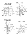
- the position of each picture element on the original screen may sequentially be transformed in accordance with a procedure of transformation processing in Figs. 1(A) through 1(D).
- the fold line L1 is set on an original part of image OIG on a x-y plane in an orthogonal coordinate system.
- the original part of image OIG is translated in parallel to an x1 axis direction by a distance + ⁇ so that the set fold line L1 is aligned with a y1 axis and is rotated through + ⁇ in a counterclockwise direction, as shown in Figs. 1(A) and 1(B).
- a part of image OIGN which belongs to a negative area in the x1 axis direction (-x1, y1)(-x1, -y1) is folded up along the y1 axis (hence, the fold line L1) to overlap the part of image OIGN over the remaining part of image OIGP present in a positive area of the x1 axis direction (x1, y1)(x1, -y1).
- the part of image OIGN is transformed to take a reversed form of the original image OIG (denoted by oblique lines).
- the whole image executed under such a folding transformation processing is represented on the x1 y1 plane.
- a fold boundary line L2 is set which is parallel to the fold line L1 on the part of image OIGN and the part of image OIGP mutually overlapping and then a part of area ER (refer to Fig. 1(c)) between the parts of images OIGN and OIGP is non-linearly compressed.
- the non-linear compression is carried out in such a way that the part of the image wound on the cylindrical image CYL obtained through a perspective view from an upward direction as described above with reference to Fig. 8 is produced on the x2, y2 plane.
- the upper section of the part of image OIGN which belongs to the area ER is transformed into a part of image OIG3 representing the cylindrical surface through the non-linear compression processing with respect to the one axis of the x2 axis direction.
- a plane lower part of image OIGP which belongs to the area ER is transformed into the part of image OIG4 (refer to Fig. 1(c)) representing the cylindrical surface through the non-linear compression processing with respect to the x2 axis.
- the parts OIG1, OIG2 other than the area ER which belong to the parts of images OIGN, OIGP shown in Fig. 1(C) are not subjected to the non-linear compression transformation.
- a fourth transformation step the whole transformed image obtained as shown in Fig. 1(C) is rotated by + ⁇ in the clockwise direction and translated in parallel (shifted) to the x2 direction by - ⁇ as appreciated from Fig. 1(D).
- the above-described parallel translation and rotation transformations means such steps as to return the position of the whole image moved by the parallel translation and rotation transformation executed as shown in Fig. 1(A) to the original image position.
- the part of transformed image OIG4 appears on the screen from the folded line L1 to the lower fold boundary line L22 which has been subjected to the non-linear compression and the part of transformed image OIG3 is also present between the fold line L1, an upper fold boundary line L21 drawn along a position which is axially symmetric to the lower fold boundary line L22 with respect to the fold line L1, and the upper part of image OIG1 which has not been subjected to the non-linear compression transformation is present outside of the upper fold boundary line L21.
- the part of transformed image OIG2 which has not been subjected to the non-linear compression transformation is subjected to such a transformation that a corresponding part of the original image OIG on the x-y plane is translated in parallel by the distance + ⁇ along the x axis (Fig. 1(A)), is then rotated by the angle + ⁇ in the counterclockwise direction (Fig. 1(B)), and is, in turn, rotated in the clockwise direction and translated in parallel to the x axis direction by - ⁇ (Fig. 1(D)).
- a position (X, Y) of each picture element on the X, Y plane in an area of the transformed part of image OIG2 can be expressed in the following equation by transforming a position (x, y) in the corresponding part of image present on the x, y plane.
- the part of transformed image OIG4 is obtained by parallel translating the corresponding part of transformed image OIG by + ⁇ (Fig. 1(A)), rotating that part through the angle + ⁇ in the counterclockwise direction (Fig. 1(B)), transforming that part in the non-linear compression (Fig. 1(C)). and rotating that part through the angle + ⁇ in the clockwise direction and translating that part in parallel by the distance - ⁇ .
- a position of each picture element (x, y) present on the part of original image OIG corresponding to the part of transformed image OIG4 is expressed relatively to a reference position (x o , y o )
- a position (X, Y) on the transformed image PIG of each picture element can be expressed in the following equation.
- a first term of the right side represents an amount of the parallel translation of the part of image with respect to the screen after processing of the non-linear compression transformation and R*( ⁇ ) denotes a rotation matrix in which the image on the screen is rotated through + ⁇ in the counterclockwise direction.
- the rotation matrix R*( ⁇ ) may be expressed as
- R*(- ⁇ ) denotes the coordinate position after the processing of the non-linear compression transformation is rotated through - ⁇ in the counterclockwise direction and may be expressed as follows:
- the second matrix in the equation (2) may be expressed as follows.
- Equation (5) the right side denotes the execution of the non-linear compression transformation.
- F denotes an operator for obtaining a value in the X ordinate after transformation as expressed below:
- r denotes a radius of the cylindrical image CYL (refer to Figs. 1(A) through 1(D)) used for the non-linear compression transformation and is expressed by the following equation:
- the fourth matrix of the right-side second term of the above equation (2) i.e., indicates that the position of each picture element (x, y) before the transformation processing is translated in parallel by the distance corresponding to the coordinates (x o , y o ) of the reference position. Consequently, the reference position (x o , y o ) is placed on a position which coincides with an origin of x1 y1 plane (Fig. 1(B)) after transformation.
- the part of transformed image OIG3 is derived from the following procedure: the corresponding part of the original part of image OIG is translated in parallel by + ⁇ (refer to Fig. 1(A)), rotated through the angle + ⁇ in the counterclockwise direction and folded back (refer to Fig. 1(B)), transformed through the non-linear compression (refer to Fig. 1(C)), and finally rotated through the angle + ⁇ in the clockwise direction together with the parallel translation by - ⁇ (refer to Fig. 1(D)).
- the part of transformed image OIG3 is derived in the similar transformation procedure as the other part of transformed image OIG4 except the above-described fold back transformation procedure.
- the part of transformed image OIG3 can be expressed in the following equation.
- the part of transformed image OIG1 is derived from the following procedure: after parallel translation by + ⁇ , the original image thereof is subjected to the rotation transformation through the angle + ⁇ in the counterclockwise direction and is folded (refer to Fig. 1(B)), and thereafter undergoes the rotation transformation through + ⁇ in the clockwise direction and parallel translation by - ⁇ . Consequently, each picture element in the part of transformed image OIG1 is transformed into a position with respect to the original image OIG which can be expressed in the following equation.
- a difference of the above equation (11) from the equation (9) lies in the use of a coefficient -1 in place of the operator -F in the second matrix of the right-side second term. This represents that in the case of equation (11) the image before subjection of transformation is turned over through the fold back transformation processing without the non-linear compression transformation.
- the parts of transformed image OIG2, OIG4, OIG3, and OIG1 constituting the transformed picture PIG can be obtained by transforming the image on the original part OIG into such positions as to satisfy the transformation equations represented by equations (1), (2), (9), and (11).
- the equation (1) represents that the part of transformed image OIG2 is returned to the same position as the original part of image OIG as the result of a series of transformation steps.
- the following equation can be substituted for the equation (1) if the intermediate series of transformation processings are included.
- the transformation equations applied to all of the parts of image OIG2, OIG4, OIG3, and OIG1 can be represented in the following general formula.
- T* denotes a matrix in which the operator F or a numerical valve substituted for the operator F is included for each arithmetic operation.
- the non-linear compression transformation equation represented by the equation (6) can be obtained by the utilization of the relationship shown in Fig. 3.
- the width D can be expressed as follows since the part of transformed image OIG4 having the width D is wound on the angular range of ⁇ /2 at a quarter lower part of an outer surface of the cylindrical image CYL.
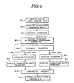
- the data on the original image OIG (refer to Fig. 1(A)) is sequentially written into an input image memory together with a predetermined address data (, i.e., input image address data). If an output image address is inversely transformed into the input image address in order to sequentially access the input image address corresponding to the output image address required for the display of the output image after transformation of the input image, the transformed output image (refer to Fig. 1(D)) can be read out from the input image memory.
- a predetermined address data i.e., input image address data
- a position (X, Y) of transformed image PIG (hence, output image address) is inputted.
- any input image is not present in a negative area outside the fold line L1 and an inverse transform of the non-linear compression is necessary for an area between the fold line L1 and fold boundary line L2.
- a step SP4 of Fig. 4 the inverse transform of the non-linear compression transformed image on the x2, y2 plane is executed so as to form the transformed image on the x1, y2 plane as described above with reference to Fig. 1(B).
- a fold back transform processing is executed so as to unfold the folded image.
- a point (x2, y2) of the part of image OIG4 in which the image is not turned over a point (x14, y14) obtained on the x1, y1 plane through the transformation is expressed as follows.
- a point (x2, y2) within the part OIG3 in which the image is turned over a point (x13, y13) obtained on the x1, y1 plane through the transformation is expressed as follows.
- F ⁇ 1 denotes an operator for executing the inverse transform of the non-linear compression represented by F.
- a point (x2, y2) within the part OIG2 in which the contents of image is not turned over a point (x12, y12) obtained on the x1, y1 plane through the transformation is expressed as follows.
- the fold-back transform outputs for the parts of image OIG1 and OIG3 are obtained in the step SP5 and are subjected to the rotation and parallel translation transforms in the next steps SP6 and SP7, for the other parts of image OIG2 and OIG4, they are directly subjected to the rotation and parallel translation transformations without the fold-back transform in the next steps SP8 and SP9, respectively.
- Such series of transforms are executed respectively for the points (x11, y11), (x12, y12), (x13, y13), (x14, y14) on the x1, y1 plane related to the parts of transformed image OIG1, OIG2, OIG3, and OIG4.
- the output image address allocated to each picture element included in the parts of transformed images OIG1, OIG2, OIG3, and OIG4 is specified by a sequential specification of an output address allocated to each picture element of the transformed image PIG described above with reference to Fig. 1(D)
- the input image address allocated to a picture element located at a position expressed by the corresponding one of the above-described equations (30) through (33) can be fetched from the input image memory as the read-out address.
- the image data constituting each part of the transformed image can be read out of the input image memory. It should be noted that it becomes practically necessary to select with a higher priority the image data on a part of transformed image which is located at an upper side of the mutually opposing parts of the transformed image, in a case when a plane image having a page turned-over effect as shown in Fig. 1(D) is produced.
- the order of priority for the transformed image exhibiting the page turn-over effect in Fig. 1(D) is set in such a way that the part of image OIG1 has a higher priority than the part of image OIG2 and the part of image OIG3 has a higher priority than the part of image OIG4.
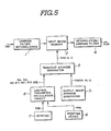
- FIG. 5 A system for transforming image signals which achieves the above-described series of transformation processing is shown schematically in Fig. 5.
- the input image data IND is sequentially read in the input image memory 2 via a low pass filter/interpolation circuit 1.
- the read image data is, in turn, read out by means of a read-out address signal RAD produced in a read-out address generator 3 and transmitted as an output image data OUD via an interpolation/low pass filter circuit 4.
- the read-out address generator 3 receives an output image address signal OADD generated by an output image address generator 5.
- the read-out address generator 3 receives a reference point signal (h o , v o ) obtained through an arithmetic operation, rotation transformation matrix data AR, B11, B21, B12, and B22 calculated on the basis of angle ⁇ in the rotation transform, and a value of radius r of the above-described cylindrical image CYL, these signals and data being derived from a control parameter calculation circuit 8 on the basis of data PPD representing a preset parameter inputted from a pointing device 6 and position assignment data PDD inputted from a joystick (control stick) 7.
- the read-out address generator 3 executes respective transform calculations for the four transformable parts of image OIG1, OIG2, OIG3, and OIG4 as described above with reference to Figs. 1(A) through 1(D) on the basis of the output image address signals OADD, reference point signal (h o , v o ), rotation transformation matrix data AR, B11, B21, B12, and B22, and radius r of the above-described cylindrical image CYL (in addition, a signal S-D to be described later) and read out the input image data which is to be the contents of image specified by the output image address fetched from the input image memory 2.
- the read-out address generator 3 has an internal circuit configuration shown in Fig. 6 and executes a sequential transform processing of each signal corresponding to the inverse transform steps shown in Fig. 4.
- both output image address signal OADD produced from the output image address generator 5 and reference point signal (h o , v o ) produced from the control parameter calculation circuit 8 are signals represented by addresses of respective picture elements on a raster screen (this is called real addresses).
- the read-out address signals RAD to be supplied from the read-out address generator 3 to the input image memory 2 need to be converted to data having the contents of the real addresses.
- the reference point (x o , y o ) on the basis of the above-described definition can correspond to the real address (h o , v o ).
- Such a conversion from the x, y coordinates and X, Y coordinates to corresponding real addresses (h, v) and (H, V) is executed simultaneously when the read-out address generator 3 executes the rotation transform.
- the read-out address generator 3 as shown in Fig. 6, the signal (H, V) indicative of the real address supplied from the output image address generator 5 as the output image address signal OADD is supplied to adders 16, 17 of a parallel translation (shift) circuit 15.
- the adders 16, 17 receive respective reference point signals (h o , v o ) supplied from the control parameter calculation circuit 8 as subtraction inputs so as to produce the addition outputs (H-h o ) and (V-v o ) representing the parallel translation processing such that the reference point (h o , v o ) is shifted to an origin.
- the addition outputs (H-h o ) and (V-v o ) are sent to a multiplier 19 in the rotation transform circuit 18.
- the reference point signal (h o , v o ) is derived from the control parameter calculation circuit 8 on the basis of the change in the output PDD of the joystick 7 and the position of the reference point (h o , v o ) is changed by an operation of joystick 7 so that the visual effect of the page being folded gradually can be achieved.
- the multiplier 19 multiplies the transformed data AR by the address signals H-h o and V-v o .
- the transformed data AR is derived from the control parameter calculation circuit 8 and the value of R*( ⁇ ) in the above-described equation (20) is obtained in the control parameter calculation circuit 8 as data having the contents expressed in the following equation multiplied by conversion coefficients in the equations (34) through (37).
- the data of angle ⁇ for rotation transform is previously inputted to the control parameter calculation circuit 8 using the pointing device 6.
- the control parameter calculation circuit 8 outputs the rotation transform data AR calculated from the equation (40).
- the output data RV01 appearing on an output terminal of the multiplier 19 is thus expressed by the following equation.
- the rotation transform data AR includes a conversion coefficient for converting the address (h, v) and (H, V) to square lattice coordinates (x, y) and (X, Y) (as shown in the above equation (40))
- the contents of output data RV01 are converted into the x, y coordinates and X, Y coordinates described with reference to the equations (18) through (33), on the basis of which the inverse transform arithmetic operation is executed at the subsequent stage of non-linear compression inverse transform circuit 20.
- the non-linear compression inverse transform circuit 20 calculates the non-linear compression inverse transform using the data of radius r sent from the control parameter calculation circuit 8. Specifically, an inverse transform calculation circuit 21 constituting the non-linear compression inverse transform circuit 20 calculates data x2 of the outputs RV01 produced from the previous stage of rotation transform circuit 18 in the axial direction of x2 and the calculation result is sent to a selection switching circuit 22.
- the selection switching circuit 22 receives directly the data x2 and enables the output of data on the part of image not requiring this inverse transform without passage through the non-linear compression inverse transform calculation circuit 21 when the data on the part of image not requiring such a transform is received.
- the selection switching circuit 22 receives as selective switching control signals CH x2 axis direction data x2 and a transform region specification signal SD (corresponds to the region D in Fig. 2) indicating that data on the regions of the parts of transformed image OIG3 and OIG4 requiring the inverse transform of non-linear compressions have reached from the circuit 8.
- the selection switching circuit 22 selects the output of the non-linear compression inverse transform calculation circuit 21 and outputs it as the output data x1 of the non-linear compression inverse transform circuit 20 upon arrival of the data corresponding to the parts of transformed image OIG3 and OIG4 and outputs the data x2 directly as the data x1 constituting the output NCOMP of the non-linear compression inverse transform circuit 20 upon arrival of the picture element data of the other parts of transformed image OIG1 and OIG2.
- a y-axis component y2 of the output RV01 from the multiplier 19 is directly outputted as the y-axis data y1 of the output NCOMP.
- the non-linear compression inverse transform circuit 21 calculates the above equations (25) and (26) by means of the following equation. After the calculation is executed, a minus sign attached to the term of operator F ⁇ 1 as a minus exponent is operated arithmetically at the subsequent stage of rotation transform circuit 23 in order to simplify the construction.
- the rotation transform circuit 23 executes the arithmetic operation of the equations (30) through (33) and the conversion of data represented by the square lattice coordinates (x1, y1) to the real address data (h, v).
- the terms cos ⁇ and -sin ⁇ are provided for the axial direction of x, as appreciated from the equation (4).
- the inverse transform operator F ⁇ 1 and minus sign in the coefficient 1 are used as shown in the equations (26) and (29).
- the x-axis component x1 among the outputs NCOMP of the non-linear compression inverse transform circuit 20 is sent to multipliers 25, 26 in which the rotation transform data B11 and B21 expressed in the following equations are multiplied by the component x1.
- the multiplied output of the multiplier 25 is directly sent to an adder 27 and is sent to an adder 29 via a sign inverter 28.
- the multiplied output of the multiplier 26 is directly sent to an adder 30 and sent to an adder 30 via a sign inverter 31.
- the y-axis component y1 among the non-linear compression inverse transformed outputs NCOMP is sent to the multipliers 35, 36 in which the rotation transform data B12, B22 expressed in the following equations are multiplied by the y-axis component y1.
- the adders 27, 30 directly receive the results of multiplication from the multipliers 25, 26 respectively in which the x-axis component x1 among the non-linear compression inverse transform outputs NCOMP is multiplied by the rotation transform data B11, B12.
- the adders 29, 32 receive the results of multiplication from the multipliers 25, 26 via the sign inverters 28, 31. Consequently, the result of calculations from the equations (44) and (46) are sent to the adders 27, 30 and the result of calculations from the equations (43) and (45) is sent to the adders 29, 32, respectively.
- This arithmetic operation means that the reference point (h o , v o ) is returned to the original position.
- output terminals of adders 43, 44 in the parallel translation (shift) circuit 40 appear addresses v a , v b in the y-axis direction for the parts of image at the front and rear sides of the transformed image PIG among the original image OIG (refer to Fig. 1(A)).
- These address signals h a , h b , v a , and v b are sent as the address data (h, v) of the read-out address signal RAD, with the higher priority taken to the address data corresponding to the rear side parts of image, i.e., OIG1, OIG3 than the front side parts of image, i.e., OIG2, OIG4 as appreciated from Fig. 1(D).
- the read-out address generator 3 in a case when the generator 3 carries out an image transformation such that the input image can be transformed to the output image having the page turn-over effect, the read-out address generator 3 is so constructed as to generate sequentially the transformed output image address and to execute an arithmetic operation of the inverse transform of the sequentially generated output image address into the read-out address signal RAD so that the part of image data required for the appearance of page turn-over effect among the image data stored in the input image data can assuredly be read out.
- Parameters representing a locus for a page to be turned over is preset in the control parameter calculation circuit 8 (refer to Fig. 5) using the pointing device 6.
- the data on the reference point (h o , v o ), rotation transform data AR, B11, B21, B12, and B22 calculated on the basis of angle ⁇ for the rotation transform, and data on the radius of the cylindrical image CYL, these data being generated on the basis of the preset parameters are modified by means of the joystick 7. Consequently, the reference point (h o , v o ), angle ⁇ of the rotation transform, and radius r of the above-described cylindrical image CYL can be changed in accordance with the positions specified by the joystick 7. Therefore, the output image data generating the page turn-over effect as if a series of changes from the beginning of page turn-over to the end of page turn-over were viewed perspectively from an upper position of the screen can be read out from the input image memory 2.
- the transformation of image signals with the page turn-over effect to be arithmetically operated as a three-dimensional surface can easily be achieved by the two-dimensional (plane) data transform and by one-dimensional compression transform of the part of output image constituting the surface part of the output image. Consequently, the effect of page turning over can easily be achieved with a simple construction.
Landscapes
- Engineering & Computer Science (AREA)
- Multimedia (AREA)
- Signal Processing (AREA)
- Studio Circuits (AREA)
- Image Processing (AREA)
- Holo Graphy (AREA)
- Television Systems (AREA)
Claims (21)
- Verfahren zur Durchführung einer Videobild-Transformation auf einem Videobildschirm mit den Verfahrensschritten:a) Speichern eines Eingangs-Videobildes (OIG, IM) in einer Speichereinrichtung,b) Definieren einer zweidimensionalen Adressenebene in einem Speicherbereich der Speichereinrichtung,c) Festlegen einer ersten Linie (L1) in der Adressenebene, um diese in einen ersten und einen zweiten Bereich zu unterteilen,d) Festlegen einer zweiten und einer dritten Linie (L21, L22) in dem ersten und dem zweiten Bereich der Adressenebene,e) Berechnen von Adressendaten der Adressenebene zur Gewinnung von transferierten Adressendaten in der Weise, daß die Adressendaten des ersten Bereichs in Bezug auf die erste Linie symmetrisch transformiert werden,f) Berechnen der genannten Adressendaten zwischen der ersten und der zweiten Linie und zwischen der ersten und der dritten Linie in der Weise, daß die Adressendaten zwischen der ersten und der zweiten Linie und zwischen der ersten und der dritten Linie mit nichtlinearer Kompression längs einer senkrecht zu der ersten Linie verlaufenden Achse transformiert werden,e) Auslesen des Eingangs-Videobildes aus der Speichereinrichtung und Erzeugen eines Ausgangs-Videobildes nach Maßgabe der berechneten Adressendaten, wodurch das Ausgangs-Videobild so betrachtet werden kann, als ob es längs der ersten Linie umgewendet würde.
- Verfahren nach Anspruch 1 mit den weiteren Verfahrensschritten:h) Transformieren der Adressenebene mit Parallelverschiebung und Drehung in der Weise, daß die erste Linie mit einer Achse der Adressenebene zusammenfällt, bevor die Transformation mit Parallelverschiebung und Drehung ausgeführt wird, undg) inverse Parallelverschiebung und Drehung durch Transformieren der Adressenebene in der Weise, daß die Achsen der Adressenebene in ihren ursprünglichen Zustand zurückgeführt werden.
- System zur Durchführung einer Videobild-Transformation auf einem Videobildschirm mita) einer ersten Einrichtung (2) zum Speichern von Eingangs-Bilddaten (IM),b) einer zweiten Einrichtung (5) zum sequentiellen Erzeugen eines Ausgangsbild-Adressen-Positionssignals,c) einer dritten Einrichtung (6) zum Voreinstellen von Parametern, die einen Ort repräsentieren, an dem ein Ausgangssignal des Videobildes so umgewendet wird, als ob ein Blatt Papier hochgefaltet würde,d) einer vierten Einrichtung (7) zum sequentiellen Erzeugen von Positionsbestimmungssignalen, die für eine Verschiebung des Eingangsbildes in einer zweidimensionalen Ebene kennzeichnend sind,e) einer fünften Einrichtung (8) zum Berechnen von Werten, die ein Referenz-Positionspunkt-Signal des Eingangsbildes (IM) in der zweidimensionalen Ebene, auf dessen Basis das Eingangsbild verschoben wird, ferner Drehungs-Transformationsmatrix-Daten, die auf einem vorgegebenen Winkel (ϑ) basieren, um den die zweidimensionale Ebene gedreht wird, sowie Radiusdaten (r) auf einem virtuellen geometrischen Bild (CYL), auf dem ein Teil des Eingangsbildes aufgewickelt wird, enthalten, wobei das Referenz-Positionspunkt-Signal, die Drehungs-Transformationsmatrix-Daten und die Radiusdaten auf von der dritten Einrichtung (6) abgeleiteten voreingestellten Parametern und auf von der vierten Einrichtung (7) abgeleiteten Positionsbestimmungssignalen basieren,f) einer sechsten Einrichtung (3)- zur Durchführung arithmetischer Transformationsoperatinen für transformierbare Teile eines Ausgangs-Videobildes, wobei diese transformierbaren Teile durch einen ersten Teil definiert sind, der einen hinteren Teil des Ausgangs-Videobildes repräsentiert, der auf einer oberen Fläche des genannten geometrischen Bildes (CYL) aufgewickelt ist, wie es durch den Videobildschirm betrachtet wird, ferner durch einen zweiten Teil, der einen vorderen Teil des Ausgangs-Videobildes repräsentiert, der sich außerhalb eines Projektionsbereichs des geometrischen Bildes (CYL) befindet, durch einen dritten Teil, der den vorderen Teil des Ausgangs-Videobildes repräsentiert, der auf einer unteren Fläche des geometrischen Bildes (CYL) aufgewickelt ist, wie es durch den Videobildschirm betrachtet wird, und durch einen vierten Teil, der den hinteren Teil des Ausgangs-Videobildes repräsentiert, der außerhalb des aufgewickelten ersten Teils liegt, so daß er den zweiten Teil überlappt, wobei diese arithmetischen Operationen auf der Basis des Referenzpunktsignals, der Drehungs-Transformationsmatrix-Daten und der Radiusdaten des geometrischen Bildes (CYL) erfolgen, die durch die fünfte Einrichtung (8) berechnet werden,- und zum Auslesen der Eingangs-Bilddaten, deren Inhalte das Ausgangsbild ergeben sollen und die durch die von der zweiten Einrichtung erzeugten Ausgangsbild-Adressen-Positionssignale spezifiziert werden, undg) einer siebten Einrichtung zum Anzeigen des Eingangs-Videobildes, dessen Daten in der ersten Einrichtung (2) gespeichert sind, und zum Auslesen der ersten Einrichtung (2) durch die sechste Einrichtung (5) nach Maßgabe der Ausgangsbild-Adressen-Positionssignale auf dem Videobildschirm, derart daß der ganze Bildschirm so betrachtet werden kann, als ob ein Blatt Papier um das geometrische Bild herum aufgefaltet würde.
- Verfahren nach Anspruch 3, dadurch gekennzeichnet, daß die sechste Einrichtung (3) enthält:a) eine erste Parallelverschiebungs-Schaltung (15), die von der zweiten Einrichtung die Ausgangs-Adressensignal und von der fünften Einrichtung das Referenzpunktsignal aufnimmt und beide Signale für jede Achse der zweidimensionalen Ebene addiert, um eine Parallelverschiebung zu bewirken, durch die der Referenzpunkt des Ausgangsbildes in den Ursprung des zweidimensionalen Ebene bewegt wird,b) eine erste Drehungs-Transformationsschaltung (18) zur Durchführung einer Transformation mit Drehung des Positions-Ausgangssignals der Parallelverschiebungs-Schaltung (15) um einen ersten vorbestimmten Winkel, derart daß die zentrale Achse des geometrischen Bildes (CYL) mit einer Achse der zweidimensionalen Ebene zusammenfällt, wobei eine der von der fünften Einrichtung (8) abgeleiteten Drehungs-Transformationsmatrix-Daten verwendet wird,c) eine Schaltung (20) zur Transformation mit inverser nichtlinearer Kompression für die Bearbeitung des genannten ersten und dritten Teils ausschließlich in Bezug auf die zu der einen Achse orthogonalen anderen Achse der zweidimensionalen Ebene unter Verwendung der Radiusdaten (r) aus der fünften Einrichtung (8) und zur Weitergabe der Daten über den zweiten und den vierten Teil und die eine Achse der zweidimensionalen Ebene, ohne daß diese der inversen Transformation mit nichtlinearer Kompression unterworfen werden,d) eine zweite Drehungs-Transformationsschaltung (23) zur Durchführung einer Transformation mit Drehung des Positions-Ausgangssignals der Schaltung (20) zur inversen Transformation mit nichtlinearer Kompression um einen zweiten vorbestimmten Winkel, derart daß die zentrale Achse des geometrischen Bildes (CYL) in die ursprüngliche Position zurückgeführt wird, wobei die anderen der von der fünften Einrichtung (8) abgeleiteten Drehungs-Transformationsmatrix-Daten verwendet werden,e) eine zweite Parallelverschiebungs-Schaltung (40), die von der zweiten Drehungs-Transformationsschaltung (23) das Positions-Ausgangssignal und von der fünften Einrichtung (8) das Referenz-Positionspunkt-Signal aufnimmt und beide Signale für jede Achse der zweidimensionalen Ebene addiert, um die Parallelverschiebung in der Weise auszuführen, daß der Referenzpunkt des Ausgangsbildes in die ursprüngliche Position zurückgeführt wird, undf) eine Prioritätsauswahlschaltung (45) zum Auswählen des aus der zweiten Parallelverschiebungs-Schaltung (40) kommenden Positions-Ausgangssignals des ersten und vierten Teils des Ausgangsbildes mit höherer Priorität als die des zweiten und dritten Teils des Ausgangsbildes und zum Ausgeben des Positions-Ausgangssignals der zweiten Parallelverschiebungs-Schaltung (40) als Adressensignal an die erste Einrichtung (2).
- System nach Anspruch 3 oder 4, dadurch gekennzeichnet, daß die vierte Einrichtung (7) die Positionsbestimmungssignale sequentiell in der Weise erzeugt, daß die betreffenden Werte des Referenzpunkts, der erste vorbestimmte Winkel und der Radius so variiert werden, daß das Ausgangs-Videobild allmählich umgewendet wird.
- System nach Anspruch 5, in dem die vierte Einrichtung ein Joystick (7) ist.
- System nach einem der Ansprüche 3 bis 6, dadurch gekennzeichnet, daß das von der vierten Einrichtung (7) erzeugte Ausgangsbild-Adressen-Positionssignal und das von der fünften Einrichtung (6) erzeugte Referenz-Positionspunkt-Signal Signale sind, die Adressen der betreffenden Bildelemente auf einem Rasterbildschirm repräsentieren.
- System nach Anspruch 7, dadurch gekennzeichnet, daß die erste und die zweite Drehungs-Transformationsschaltung (18, 23) die Transformation unter Verwendung eines Umwandlungskoeffizienten zur Umwandlung aller Positionsadressendaten der zweidimensionalen Ebene in Positionsadressendaten auf dem Rasterbildschirm ausführen.
- System nach einem der Ansprüche 4 bis 8, dadurch gekennzeichnet, daß die zweite Drehungs-Transformationsschaltung (23) die die Drehung bewirkende Transformation zusammen mit einer Transformation zur Rückfaltung der von der Schaltung (20) zur Transformation mit inverser nichtlinearer Kompression ausgegebenen Positionsadressendaten bewirkt, die dem ersten und dem vierten Teil des Ausgangsbildes entsprechen.
- System nach einem der Ansprüche 4 bis 9, dadurch gekennzeichnet, daß der zweite vorbestimmte Winkel dem negativen Wert des ersten vorbestimmten Winkels entspricht.
- System nach einem der Ansprüche 4 bis 10, dadurch gekennzeichnet, daß das Koordinatensystem der zweidimensionalen Ebene jedesmal geändert wird, wenn die Transformation durchgeführt wird.
- Verfahren zur Durchführung einer Videobild-Transformation auf einem Videobildschirm mit den Verfahrensschritten:a) Definieren einer zweidimensionalen Adressenebene in einem Speicherbereich,b) Speichern eines Eingangs-Videobildes in dem Speicherbereich in der Weise, daß alle Videodaten eines Bildelements des Videobildes an einer entsprechenden Adresse angeordnet werden,c) virtuelles Anordnen eines zylinderförmigen Bildes (CYL), wobei der Radius (r) eines Abschnitts dieses Bildes in der im Schritt (a) definierten Adressenebene variiert wird, und Aufwickeln eines Teils des zylinderförmigen Bildes,d) Verschieben des zylinderförmigen Bildes (CYL) auf der Adressenebene in einer vorbestimmten Richtung, wobei sein Radius (r) zeitlich so geändert wird, daß die Adressenebene längs der vorbestimmter Richtung umgewendet wird,e) Durchführen einer Parallelverschiebung und Drehung der gesamten Adressenebene, einer in Bezug auf die vorbestimmte Richtung nichtlinearen Kompression für vordere und hintere Teile der Adressenebene, die bei vertikaler Betrachtung durch den Videobildschirm auf einer Fläche des zylinderförmigen Bildes (CYL) aufgewickelt sind, und einer Rückfaltung des hinteren Teils der Adressenebene,f) inverses Transformieren der in Schritt (e) gewonnenen transformierten Adressendaten in der Weise, daß das Ausgangs-Videobild zurückgefaltet wird, sowie Auslesen von invers transformierten Bildadressendaten mit Priorität für den umgewendeten Teil des Ausgangsbildes gegenüber den Eingangsbild-Adressendaten, undg) Anzeigen des Eingangsbildes auf dem Videobildschirm auf der Basis der Eingangsbild-Adressen, wodurch das Videobild auf dem Videobildschirm so betrachtet werden kann, als ob eine Seite umgewendet würde.
- Verfahren nach Anspruch 1 oder 2, dadurch gekennzeichnet, daß der Schritt (d) ferner den Schritt beinhaltet, daß die zweite und die dritte Linie (L21, L22) zueinander parallel verlaufen.
- Verfahren nach einem der Ansprüche 1, 3 und 13, dadurch gekennzeichnet, daß dann, wenn die zweite und dritte Linie (L21, L22) zueinander und zu der ersten Linie (L1) parallel verlaufen, ein imaginärer Zylinder (CYL) definiert wird, um den das Videobild gewunden wird.
- Verfahren nach einem der Ansprüche 1, 2, 13 und 14, dadurch gekennzeichnet, daß der Abstand zwischen der ersten Linie (L1) und der zweiten Linie (L21) etwa derselbe ist wie der Abstand zwischen der ersten Linie (L1) und der dritten Linie (L22).
- Verfahren nach einem der Ansprüche 1, 2 und 13 bis 15, dadurch gekennzeichnet, daß die zweite Linie (L21) und die dritte Linie (L22) eine imaginäre geometrische Form definieren, über die das Videobild transformiert wird.
- Verfahren nach einem der Ansprüche 1, 2 und 13 bis 16, gekennzeichnet durch den Schritt, daß die erste Linie (L1) bewegt wird, um eine Umblättereffekt zu erzielen.
- Verfahren nach einem der Ansprüche 1, 2 und 13 bis 17, dadurch gekennzeichnet, daß der Schritt (d) ferner das Verändern des Abstands zwischen der zweiten und der dritten Linie (L21, L22) beinhaltet.
- Verfahren nach einem der Ansprüche 1, 2 und 13 bis 18, gekennzeichnet durch das Verschieben der ersten Linie (L1) in einer vorbestimmten Richtung auf der Adressenebene in der Weise, daß das Ausgangsbild um eine geometrische Form gewunden wird, die die erste Linie (L1) zur Achse hat.
- Verfahren nach einem der Ansprüche 1, 2 und 13 bis 19, dadurch gekennzeichnet, daß der Radius (r) der geometrischen Form (CYL) zeitlich verändert wird.
- Verfahren nach einem der Ansprüche 1, 2 und 13 bis 20, dadurch gekennzeichnet, daß die vorbestimmte Richtung senkrecht zu der ersten Linie (L1) verläuft.
Priority Applications (1)
| Application Number | Priority Date | Filing Date | Title |
|---|---|---|---|
| AT85116591T ATE63797T1 (de) | 1984-12-27 | 1985-12-27 | Verfahren und vorrichtung zur bewirkung einer videobildtransformation. |
Applications Claiming Priority (2)
| Application Number | Priority Date | Filing Date | Title |
|---|---|---|---|
| JP59281225A JP2526857B2 (ja) | 1984-12-27 | 1984-12-27 | 画像信号変換方法 |
| JP281225/84 | 1984-12-27 |
Publications (3)
| Publication Number | Publication Date |
|---|---|
| EP0186206A2 EP0186206A2 (de) | 1986-07-02 |
| EP0186206A3 EP0186206A3 (en) | 1988-03-30 |
| EP0186206B1 true EP0186206B1 (de) | 1991-05-22 |
Family
ID=17636106
Family Applications (1)
| Application Number | Title | Priority Date | Filing Date |
|---|---|---|---|
| EP85116591A Expired - Lifetime EP0186206B1 (de) | 1984-12-27 | 1985-12-27 | Verfahren und Vorrichtung zur Bewirkung einer Videobildtransformation |
Country Status (8)
| Country | Link |
|---|---|
| US (1) | US4860217A (de) |
| EP (1) | EP0186206B1 (de) |
| JP (1) | JP2526857B2 (de) |
| KR (1) | KR930011840B1 (de) |
| AT (1) | ATE63797T1 (de) |
| AU (1) | AU586846B2 (de) |
| CA (1) | CA1286393C (de) |
| DE (1) | DE3582921D1 (de) |
Families Citing this family (60)
| Publication number | Priority date | Publication date | Assignee | Title |
|---|---|---|---|---|
| GB2181929B (en) * | 1985-10-21 | 1989-09-20 | Sony Corp | Methods of and apparatus for video signal processing |
| GB8613447D0 (en) * | 1986-06-03 | 1986-07-09 | Quantel Ltd | Video image processing systems |
| GB8622610D0 (en) * | 1986-09-19 | 1986-10-22 | Questech Ltd | Processing of video image signals |
| US4689682A (en) * | 1986-10-24 | 1987-08-25 | The Grass Valley Group, Inc. | Method and apparatus for carrying out television special effects |
| US4689681A (en) * | 1986-10-24 | 1987-08-25 | The Grass Valley Group, Inc. | Television special effects system |
| US5070465A (en) * | 1987-02-25 | 1991-12-03 | Sony Corporation | Video image transforming method and apparatus |
| FR2638308A1 (fr) * | 1988-10-24 | 1990-04-27 | Mosaic Sa | Procede et materiel pour la commande tactile du passage d'une image a une autre dans une sequence selectionnee sur un videodisque |
| DE3843232A1 (de) * | 1988-12-22 | 1990-06-28 | Philips Patentverwaltung | Schaltungsanordnung zur geometrischen bildtransformation |
| US5444831A (en) * | 1988-12-24 | 1995-08-22 | Fanuc Ltd. | Developed product shape deciding method for a computer-aided design system |
| US5053762A (en) * | 1989-04-28 | 1991-10-01 | Microtime, Inc. | Page turn simulator |
| DE69027712T2 (de) * | 1989-05-19 | 1997-02-06 | Sony Corp | Verfahren zur Bildtransformation |
| US5063608A (en) * | 1989-11-03 | 1991-11-05 | Datacube Inc. | Adaptive zonal coder |
| JP2773354B2 (ja) * | 1990-02-16 | 1998-07-09 | ソニー株式会社 | 特殊効果装置及び特殊効果発生方法 |
| EP0449478A3 (en) * | 1990-03-29 | 1992-11-25 | Microtime Inc. | 3d video special effects system |
| US5369735A (en) * | 1990-03-30 | 1994-11-29 | New Microtime Inc. | Method for controlling a 3D patch-driven special effects system |
| US5367623A (en) * | 1990-09-25 | 1994-11-22 | Sharp Kabushiki Kaisha | Information processing apparatus capable of opening two or more windows on screen, one window containing a page and other windows containing supplemental information |
| US5283864A (en) * | 1990-10-30 | 1994-02-01 | Wang Laboratories, Inc. | Computer apparatus and method for graphical flip book |
| US5214511A (en) * | 1990-11-30 | 1993-05-25 | Sony Corporation | Image transforming apparatus |
| EP0526918A2 (de) * | 1991-06-12 | 1993-02-10 | Ampex Systems Corporation | Bildtransformation über eine gefaltete gekrümmte Oberfläche |
| JP3092259B2 (ja) * | 1991-10-14 | 2000-09-25 | ソニー株式会社 | 画像処理装置 |
| US5592599A (en) * | 1991-12-18 | 1997-01-07 | Ampex Corporation | Video special effects system with graphical operator interface |
| JP3117097B2 (ja) * | 1992-01-28 | 2000-12-11 | ソニー株式会社 | 画像変換装置 |
| US5351995A (en) * | 1992-01-29 | 1994-10-04 | Apple Computer, Inc. | Double-sided, reversible electronic paper |
| US5544295A (en) * | 1992-05-27 | 1996-08-06 | Apple Computer, Inc. | Method and apparatus for indicating a change in status of an object and its disposition using animation |
| US5422988A (en) * | 1992-06-25 | 1995-06-06 | International Business Machines Corporation | Method and apparatus for rendering a three-dimensional object with a plurality of dots |
| US5463725A (en) * | 1992-12-31 | 1995-10-31 | International Business Machines Corp. | Data processing system graphical user interface which emulates printed material |
| US5467446A (en) * | 1993-01-29 | 1995-11-14 | Colorage, Inc. | System and method for rasterizing images subject to orthogonal rotation |
| US6262732B1 (en) * | 1993-10-25 | 2001-07-17 | Scansoft, Inc. | Method and apparatus for managing and navigating within stacks of document pages |
| JP3731212B2 (ja) * | 1994-04-28 | 2006-01-05 | ソニー株式会社 | 画像特殊効果装置 |
| US5835692A (en) * | 1994-11-21 | 1998-11-10 | International Business Machines Corporation | System and method for providing mapping notation in interactive video displays |
| US5887170A (en) * | 1995-02-13 | 1999-03-23 | International Business Machines Corporation | System for classifying and sending selective requests to different participants of a collaborative application thereby allowing concurrent execution of collaborative and non-collaborative applications |
| US6356275B1 (en) | 1995-02-13 | 2002-03-12 | International Business Machines Corporation | Pixel color matching across X servers in network conferencing systems by master-participant pair mapping |
| US5557725A (en) * | 1995-02-13 | 1996-09-17 | International Business Machines Corporation | Method and system for switching between users in a conference enabled application |
| US5640540A (en) * | 1995-02-13 | 1997-06-17 | International Business Machines Corporation | Method and apparatus for translating key codes between servers over a conference networking system |
| GB9607647D0 (en) * | 1996-04-12 | 1996-06-12 | Discreet Logic Inc | Proportional modelling |
| JP4099830B2 (ja) * | 1996-09-11 | 2008-06-11 | ソニー株式会社 | 特殊効果装置、画像処理方法及び対象画像生成方法 |
| JP3677924B2 (ja) * | 1997-02-17 | 2005-08-03 | 株式会社セガ | ビデオゲーム装置の表示方法及び制御方法 |
| US6069668A (en) * | 1997-04-07 | 2000-05-30 | Pinnacle Systems, Inc. | System and method for producing video effects on live-action video |
| US6674484B1 (en) * | 2000-01-10 | 2004-01-06 | Koninklijke Philips Electronics N.V. | Video sample rate conversion to achieve 3-D effects |
| GB0007974D0 (en) * | 2000-04-01 | 2000-05-17 | Discreet Logic Inc | Processing image data |
| JP3846445B2 (ja) * | 2003-04-04 | 2006-11-15 | ソニー株式会社 | 特殊効果装置、アドレス信号生成装置、アドレス信号生成方法及びアドレス信号生成プログラム |
| JP3846446B2 (ja) * | 2003-04-04 | 2006-11-15 | ソニー株式会社 | 特殊効果装置、アドレス信号生成装置、アドレス信号生成方法及びアドレス信号生成プログラム |
| US20050231643A1 (en) * | 2004-03-26 | 2005-10-20 | Ross Video Limited | Method, system and device for real-time non-linear video transformations |
| KR100998633B1 (ko) * | 2004-06-21 | 2010-12-07 | 웨이커(에스)피티이 엘티디 | 가상 카드 게임 시스템 |
| US7794324B2 (en) | 2004-09-13 | 2010-09-14 | Pokertek, Inc. | Electronic player interaction area with player customer interaction features |
| US7898541B2 (en) * | 2004-12-17 | 2011-03-01 | Palo Alto Research Center Incorporated | Systems and methods for turning pages in a three-dimensional electronic document |
| USD683730S1 (en) | 2010-07-08 | 2013-06-04 | Apple Inc. | Portable display device with graphical user interface |
| US20120096374A1 (en) * | 2010-10-18 | 2012-04-19 | Nokia Corporation | Computer modeling |
| US9674407B2 (en) | 2012-02-14 | 2017-06-06 | Honeywell International Inc. | System and method for interactive image capture for a device having a camera |
| USD708638S1 (en) | 2012-03-07 | 2014-07-08 | Apple Inc. | Display screen or portion thereof with graphical user interface |
| USD736221S1 (en) * | 2012-10-17 | 2015-08-11 | Samsung Electronics Co., Ltd. | Portable electronic device with a graphical user interface |
| USD749637S1 (en) * | 2012-10-17 | 2016-02-16 | Samsung Electronics Co., Ltd. | Portable electronic device with a graphical user interface |
| USD747346S1 (en) * | 2012-10-17 | 2016-01-12 | Samsung Electronics Co., Ltd. | Portable electronic device with a graphical user interface |
| USD736783S1 (en) * | 2012-10-17 | 2015-08-18 | Samsung Electronics Co., Ltd. | Portable electronic device with a graphical user interface |
| USD746336S1 (en) * | 2012-10-17 | 2015-12-29 | Samsung Electronics Co., Ltd. | Portable electronic device with graphical user interface |
| USD736784S1 (en) * | 2012-10-17 | 2015-08-18 | Samsung Electronics Co., Ltd. | Portable electronic device with a graphical user interface |
| USD734765S1 (en) * | 2012-10-17 | 2015-07-21 | Samsung Electronics Co., Ltd. | Portable electronic device with a graphical user interface |
| US10486068B2 (en) | 2015-05-14 | 2019-11-26 | Activision Publishing, Inc. | System and method for providing dynamically variable maps in a video game |
| US10463964B2 (en) | 2016-11-17 | 2019-11-05 | Activision Publishing, Inc. | Systems and methods for the real-time generation of in-game, locally accessible heatmaps |
| US10709981B2 (en) | 2016-11-17 | 2020-07-14 | Activision Publishing, Inc. | Systems and methods for the real-time generation of in-game, locally accessible barrier-aware heatmaps |
Family Cites Families (16)
| Publication number | Priority date | Publication date | Assignee | Title |
|---|---|---|---|---|
| JPS50122119A (de) * | 1974-03-12 | 1975-09-25 | ||
| US3976982A (en) * | 1975-05-12 | 1976-08-24 | International Business Machines Corporation | Apparatus for image manipulation |
| GB1547119A (en) * | 1977-12-09 | 1979-06-06 | Ibm | Image rotation apparatus |
| US4283765A (en) * | 1978-04-14 | 1981-08-11 | Tektronix, Inc. | Graphics matrix multiplier |
| JPS57138685A (en) * | 1981-02-23 | 1982-08-27 | Hitachi Ltd | Graphic conversion for graphic indicator |
| JPS58108868A (ja) * | 1981-12-23 | 1983-06-29 | Sony Corp | 画像変換装置 |
| JPS58156273A (ja) * | 1982-03-11 | 1983-09-17 | Hajime Sangyo Kk | 画像情報のマスキング装置 |
| GB2119594B (en) * | 1982-03-19 | 1986-07-30 | Quantel Ltd | Video processing systems |
| US4475104A (en) * | 1983-01-17 | 1984-10-02 | Lexidata Corporation | Three-dimensional display system |
| US4594673A (en) * | 1983-06-28 | 1986-06-10 | Gti Corporation | Hidden surface processor |
| US4625290A (en) * | 1983-11-02 | 1986-11-25 | University Of Florida | Apparatus and method for producing a three-dimensional display on a video display device |
| ATE75872T1 (de) * | 1983-11-29 | 1992-05-15 | Tandy Corp | Graphisches videoanzeigesystem mit grosser aufloesung. |
| JPH0644814B2 (ja) * | 1984-04-13 | 1994-06-08 | 日本電信電話株式会社 | 画像表示装置 |
| GB2158321B (en) * | 1984-04-26 | 1987-08-05 | Philips Electronic Associated | Arrangement for rotating television pictures |
| US4685070A (en) * | 1984-08-03 | 1987-08-04 | Texas Instruments Incorporated | System and method for displaying, and interactively excavating and examining a three dimensional volume |
| US4653013A (en) * | 1984-11-19 | 1987-03-24 | General Electric Company | Altering spatial characteristics of a digital image |
-
1984
- 1984-12-27 JP JP59281225A patent/JP2526857B2/ja not_active Expired - Lifetime
-
1985
- 1985-12-06 KR KR1019850009170A patent/KR930011840B1/ko not_active Expired - Fee Related
- 1985-12-23 US US06/812,341 patent/US4860217A/en not_active Expired - Lifetime
- 1985-12-23 AU AU51590/85A patent/AU586846B2/en not_active Ceased
- 1985-12-24 CA CA000498556A patent/CA1286393C/en not_active Expired - Lifetime
- 1985-12-27 AT AT85116591T patent/ATE63797T1/de not_active IP Right Cessation
- 1985-12-27 EP EP85116591A patent/EP0186206B1/de not_active Expired - Lifetime
- 1985-12-27 DE DE8585116591T patent/DE3582921D1/de not_active Expired - Lifetime
Also Published As
| Publication number | Publication date |
|---|---|
| US4860217A (en) | 1989-08-22 |
| AU586846B2 (en) | 1989-07-27 |
| KR860005538A (ko) | 1986-07-23 |
| JP2526857B2 (ja) | 1996-08-21 |
| DE3582921D1 (de) | 1991-06-27 |
| AU5159085A (en) | 1986-07-03 |
| EP0186206A3 (en) | 1988-03-30 |
| JPS61156980A (ja) | 1986-07-16 |
| ATE63797T1 (de) | 1991-06-15 |
| KR930011840B1 (ko) | 1993-12-21 |
| EP0186206A2 (de) | 1986-07-02 |
| CA1286393C (en) | 1991-07-16 |
Similar Documents
| Publication | Publication Date | Title |
|---|---|---|
| EP0186206B1 (de) | Verfahren und Vorrichtung zur Bewirkung einer Videobildtransformation | |
| EP0437074B1 (de) | Speziale Effekte mit Polarbildkoordinaten | |
| EP0221704B1 (de) | Videosignalverarbeitung | |
| EP0208448B1 (de) | Verfahren und Schaltungen zur Videosignalverarbeitung | |
| EP0106265B2 (de) | Bilddatenverarbeitungssystem | |
| JPH10232940A (ja) | コーナ検出装置及びコーナ検出方法 | |
| KR960013365B1 (ko) | 3차원 좌표 선택방법 및 장치(method of selecting 3d) | |
| CA1254650A (en) | Methods of and circuits for video signal processing | |
| EP0841812A2 (de) | Vorrichtung und Verfahren zur Verarbeitung von Videosignalen | |
| JPH08123969A (ja) | マッピング装置 | |
| JP2008015756A (ja) | 局所領域分割による自由視点画像の生成方法、装置およびプログラム | |
| KR910009102B1 (ko) | 화상합성 장치 | |
| KR987001181A (ko) | 영상 처리 장치 및 영상 처리 방법(Device and Method for Processing Image) | |
| US6020932A (en) | Video signal processing device and its method | |
| JP3490774B2 (ja) | ジオスペシフィックテクスチャ生成の方法 | |
| JP2813881B2 (ja) | ビデオ信号処理装置 | |
| EP0435905B1 (de) | Produktion von digitalen video-effekten | |
| JPH02306782A (ja) | 画像合成装置 | |
| EP0526918A2 (de) | Bildtransformation über eine gefaltete gekrümmte Oberfläche | |
| JPH05298456A (ja) | テクスチャ・マッピング方式 | |
| JPH0654955B2 (ja) | 画像信号変換装置 | |
| JP3311905B2 (ja) | 画像処理装置 | |
| JPH0371275A (ja) | 画像変換装置及び方法 | |
| JPH05126937A (ja) | ビデオ表示装置 | |
| JP3358891B2 (ja) | Z値の透視変換処理方法及び画像処理装置 |
Legal Events
| Date | Code | Title | Description |
|---|---|---|---|
| PUAI | Public reference made under article 153(3) epc to a published international application that has entered the european phase |
Free format text: ORIGINAL CODE: 0009012 |
|
| AK | Designated contracting states |
Kind code of ref document: A2 Designated state(s): AT DE FR GB NL SE |
|
| PUAL | Search report despatched |
Free format text: ORIGINAL CODE: 0009013 |
|
| AK | Designated contracting states |
Kind code of ref document: A3 Designated state(s): AT DE FR GB NL SE |
|
| 17P | Request for examination filed |
Effective date: 19880930 |
|
| 17Q | First examination report despatched |
Effective date: 19900704 |
|
| GRAA | (expected) grant |
Free format text: ORIGINAL CODE: 0009210 |
|
| AK | Designated contracting states |
Kind code of ref document: B1 Designated state(s): AT DE FR GB NL SE |
|
| REF | Corresponds to: |
Ref document number: 63797 Country of ref document: AT Date of ref document: 19910615 Kind code of ref document: T |
|
| REF | Corresponds to: |
Ref document number: 3582921 Country of ref document: DE Date of ref document: 19910627 |
|
| ET | Fr: translation filed | ||
| PLBE | No opposition filed within time limit |
Free format text: ORIGINAL CODE: 0009261 |
|
| STAA | Information on the status of an ep patent application or granted ep patent |
Free format text: STATUS: NO OPPOSITION FILED WITHIN TIME LIMIT |
|
| 26N | No opposition filed | ||
| EAL | Se: european patent in force in sweden |
Ref document number: 85116591.0 |
|
| PGFP | Annual fee paid to national office [announced via postgrant information from national office to epo] |
Ref country code: FR Payment date: 20011212 Year of fee payment: 17 Ref country code: AT Payment date: 20011212 Year of fee payment: 17 |
|
| PGFP | Annual fee paid to national office [announced via postgrant information from national office to epo] |
Ref country code: SE Payment date: 20011227 Year of fee payment: 17 Ref country code: GB Payment date: 20011227 Year of fee payment: 17 |
|
| PGFP | Annual fee paid to national office [announced via postgrant information from national office to epo] |
Ref country code: NL Payment date: 20011228 Year of fee payment: 17 |
|
| REG | Reference to a national code |
Ref country code: GB Ref legal event code: IF02 |
|
| PGFP | Annual fee paid to national office [announced via postgrant information from national office to epo] |
Ref country code: DE Payment date: 20020109 Year of fee payment: 17 |
|
| PG25 | Lapsed in a contracting state [announced via postgrant information from national office to epo] |
Ref country code: GB Free format text: LAPSE BECAUSE OF NON-PAYMENT OF DUE FEES Effective date: 20021227 Ref country code: AT Free format text: LAPSE BECAUSE OF NON-PAYMENT OF DUE FEES Effective date: 20021227 |
|
| PG25 | Lapsed in a contracting state [announced via postgrant information from national office to epo] |
Ref country code: SE Free format text: LAPSE BECAUSE OF NON-PAYMENT OF DUE FEES Effective date: 20021228 |
|
| PG25 | Lapsed in a contracting state [announced via postgrant information from national office to epo] |
Ref country code: NL Free format text: LAPSE BECAUSE OF NON-PAYMENT OF DUE FEES Effective date: 20030701 Ref country code: DE Free format text: LAPSE BECAUSE OF NON-PAYMENT OF DUE FEES Effective date: 20030701 |
|
| EUG | Se: european patent has lapsed | ||
| GBPC | Gb: european patent ceased through non-payment of renewal fee |
Effective date: 20021227 |
|
| NLV4 | Nl: lapsed or anulled due to non-payment of the annual fee |
Effective date: 20030701 |
|
| PG25 | Lapsed in a contracting state [announced via postgrant information from national office to epo] |
Ref country code: FR Free format text: LAPSE BECAUSE OF NON-PAYMENT OF DUE FEES Effective date: 20030901 |
|
| REG | Reference to a national code |
Ref country code: FR Ref legal event code: ST |