EP0186362A1 - Gerät zum pneumatischen Spleissen von Fäden - Google Patents
Gerät zum pneumatischen Spleissen von Fäden Download PDFInfo
- Publication number
- EP0186362A1 EP0186362A1 EP85308931A EP85308931A EP0186362A1 EP 0186362 A1 EP0186362 A1 EP 0186362A1 EP 85308931 A EP85308931 A EP 85308931A EP 85308931 A EP85308931 A EP 85308931A EP 0186362 A1 EP0186362 A1 EP 0186362A1
- Authority
- EP
- European Patent Office
- Prior art keywords
- splicer
- pneumatic
- chamber
- slot
- yarn
- Prior art date
- Legal status (The legal status is an assumption and is not a legal conclusion. Google has not performed a legal analysis and makes no representation as to the accuracy of the status listed.)
- Granted
Links
- 230000000295 complement effect Effects 0.000 claims description 11
- 230000006872 improvement Effects 0.000 claims description 3
- 238000005096 rolling process Methods 0.000 claims 3
- 230000009471 action Effects 0.000 abstract description 5
- 230000007246 mechanism Effects 0.000 description 3
- 230000004048 modification Effects 0.000 description 3
- 238000012986 modification Methods 0.000 description 3
- 230000008878 coupling Effects 0.000 description 2
- 238000010168 coupling process Methods 0.000 description 2
- 238000005859 coupling reaction Methods 0.000 description 2
- 241001331845 Equus asinus x caballus Species 0.000 description 1
- 230000000740 bleeding effect Effects 0.000 description 1
- 238000010276 construction Methods 0.000 description 1
- 238000010586 diagram Methods 0.000 description 1
- 238000006073 displacement reaction Methods 0.000 description 1
- 238000005553 drilling Methods 0.000 description 1
- 230000000694 effects Effects 0.000 description 1
- 238000000034 method Methods 0.000 description 1
- 230000008569 process Effects 0.000 description 1
- 239000004753 textile Substances 0.000 description 1
Images




Classifications
-
- B—PERFORMING OPERATIONS; TRANSPORTING
- B65—CONVEYING; PACKING; STORING; HANDLING THIN OR FILAMENTARY MATERIAL
- B65H—HANDLING THIN OR FILAMENTARY MATERIAL, e.g. SHEETS, WEBS, CABLES
- B65H69/00—Methods of, or devices for, interconnecting successive lengths of material; Knot-tying devices ;Control of the correct working of the interconnecting device
- B65H69/06—Methods of, or devices for, interconnecting successive lengths of material; Knot-tying devices ;Control of the correct working of the interconnecting device by splicing
- B65H69/061—Methods of, or devices for, interconnecting successive lengths of material; Knot-tying devices ;Control of the correct working of the interconnecting device by splicing using pneumatic means
-
- B—PERFORMING OPERATIONS; TRANSPORTING
- B65—CONVEYING; PACKING; STORING; HANDLING THIN OR FILAMENTARY MATERIAL
- B65H—HANDLING THIN OR FILAMENTARY MATERIAL, e.g. SHEETS, WEBS, CABLES
- B65H2402/00—Constructional details of the handling apparatus
- B65H2402/40—Details of frames, housings or mountings of the whole handling apparatus
- B65H2402/41—Portable or hand-held apparatus
- B65H2402/414—Manual tools for filamentary material, e.g. for mounting or removing a bobbin, measuring tension or splicing
-
- B—PERFORMING OPERATIONS; TRANSPORTING
- B65—CONVEYING; PACKING; STORING; HANDLING THIN OR FILAMENTARY MATERIAL
- B65H—HANDLING THIN OR FILAMENTARY MATERIAL, e.g. SHEETS, WEBS, CABLES
- B65H2701/00—Handled material; Storage means
- B65H2701/30—Handled filamentary material
- B65H2701/31—Textiles threads or artificial strands of filaments
Definitions
- This invention relates to yarn splicing devices and in particular to pneumatic chambers therefor.
- Known prior art yarn splicers having pneumatic chambers are normally provided with a splicing chamber which has a hinged lid.
- the lid is normally arranged so that it closes onto the splicing chamber with a hinging action, the chamber being a slot or depression into which the threads to be spliced are laid.
- the air which provides the splicing action to be admitted into the chamber through a wall of the body defining the chamber rather than through the lid, because this provides the simplest mechanical arrangement.
- the mechanical operations of the splicer are performed by pneumatic action.
- the device of the invention is particularly distinguished from its predecessors by the fact that the closure member closes the splicing chamber by a sliding operation. In the preferred arrangement this is facilitated by constructing the closure member in the form of a pneumatic piston which is urged into contact with the body forming the splicing chamber by a suitable air pressure. The piston is provided at its centre with an orifice which releases a blast of air into the pneumatic chamber when it comes into registration therewith.
- the device is manually actuated and has very few parts to cause problems.
- the use of a sliding closure member and in particular the use of the pneumatic piston enables an arrangement to be provided which allows easy access to the splicing chamber when preparing the splice and avoids the. use of fragile members and complicated linkages.
- such a splicer comprises first and second bodies having respective complementary surfaces which slide relative to and in contact with one another from an open to a closed condition of the splicer and which co-operate so as to provide a pneumatic splicing chamber which is open in said open condition and closed in said closed condition, said chamber being defined by a slot which is open at each end in the said surface of a first one of said bodies and a closure surface on the complementary surface of the second body, and air supply means, including air passage means and an orifice in one of said bodies, arranged so as to admit air under pressure into the said splicing chamber when the chamber is closed.
- the invention also provides a pneumatic yarn splicer comprising first and second bodies which are joined at a pivot so as to be relatively, angularly, displaceable between a relatively wide-angle, disposition-corresponding to an open condition of the splicer and a narrower-angle disposition, corresponding to a closed condition of the splicer, in which the two bodies have complementary surfaces which co-operate to define a pneumatic splicing chamber into which a blast of air is admitted, said chamber being formed by a slot in a face of a first one of the bodies and a closure surface on the second body, said slot in said first body being open at both ends so as to receive the yarns to be joined, one from each direction, and to enable the spliced yarn to be removed, when the splicer is in its open condition, and to exhaust the blast of air when the splicer is in its closed condition, characterised in that the said pivot is situated in a plane which is substantially normal to the face containing the slot and is spaced apart therefrom such that
- the body containing the said slot has a part adapted to be held stationary relative to the operator, and the body providing the closure member contains an orifice coupled to an air supply which registers with the slot when the device is closed and admits a blast of air into the slot.
- the invention also provides an improvement by means of which the threads before being spliced are detwisted and after splicing the twist is restored to the spliced thread.
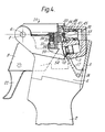
- FIG. 1 to 4 The embodiment of the invention disclosed in Figures 1 to 4 comprises a threaded splicer body 1 which is formed to be held in the hand, having a lower portion 2 defining and shaped as a hand grip and an upper open casing 3 having side walls 4, 5.
- a pivot pin 6 supported by the side walls 4, 5, defines a pivotal axis 7 and is positioned at the top and rear of the splicer body 1.
- an actuating lever 8 which extends downwards from the pivot pin 6 and a crank shaped spool valve body 9 having an elongate intermediate portion 10 between a cranked end portion mounted on the pivot pin 6 and a free end.
- the intermediate portion 10 of the spool valve body houses a conventional pneumatic spool valve 11 including a spool member 12.
- An air pressure supply is coupled to the spool valve 11 through a union 13 on the base of the spool valve body 9, through a flexible air hose 14 which passes through a bore 44 in the splicer body and through a coupling 15 provided in an axially offset position at the bottom end of the hand grip portion 2.
- Spool member 12 extends towards lever 8 outside the spool valve body 9 to form an actuator 16 which co-operates with an intermediate portion provided on the lever 8.
- Actuator 16 is biased towards lever 8 by means of a spring 17.
- Spool valve body 10 is biased downwards (clockwise as shown in Figure 1) by means of a torsion spring 18 mounted on a pin 19 which passes through the casing. Bore 44 is closed by means of a blanking plug 60.
- Actuating lever 8 is provided with bifurcated arms which extend upwards to provide pivot bearings in which the pivot pin is journalled and which also extend into the casing 3 on either side of of the spool valve body 9 to form scissor actuating members 20, 21 for actuating a scissor mechanism, described hereinafter.
- Lever 8 extends downwards out of said housing at an angle to the hand grip to form a manual operator 22 (called hereinafter “the trigger 22").
- a head assembly 23 is mounted on the casing by means of the pivot pin 6 for angular displacement relative to the casing but is normally secured thereto by a captive screw (not shown).
- Head assembly 23 comprises a cap 25 which is articulated to the pivot pin 6 and a removable cartridge 26 which is fastened on the underside of the cap by means of a screw 24.
- Cartridge 26 mounts a cylindrical sleeve 27 which is secured in the cartridge body by fastening means 28.
- Cylindrical sleeve 27 has a screw-threaded bore 29 which contains a correspondingly screw-threaded member 30 (also called herein the pneumatic chamber body 30).
- This member is provided with an external head portion 31 defining an end face 32 which is substantially curved in the vertical plane and which bears a slot 33 along a line which passes through the common axis 34 of said member and said sleeve, said slot being normally arranged parallel with the pivotal axis 7 of the pivot pin 6.
- This slot 33 comprises the pneumatic chamber of the splicer. Axis 34 of the pneumatic chamber body 30 intersects the pivotal axis 7 of the pivot pin 6.
- cylindrical sleeve 27 extends from the cartridge 26 to provide an outer cylindrical bearing surface on which are mounted two pivotable scissor blade members 35, 36.
- the latter are biased in opposite angular directions by means of springs 37, 38, so that scissors formed by the scissor blades are normally in an open condition.
- Each scissor blade member is mounted on said sleeve near its mid-point and defines an upper blade 39, 40, which normally abuts the underside of the cap 25 and a diametrically opposite lower blade 41, 42 which extends downwards towards the scissor actuating members 20, 21.
- On each respective side of the casing each top and bottom blade co-operate to form a pair of scissors.
- the external head portion 31 of the pneumatic chamber body 30 is formed with flat sides 43 parallel to the slot 33, one of which is arranged to abut the underside of the cap 25 so as to prevent rotational movement of the chamber body in the sleeve 27.
- Axial adjustment of the scissors relative to the splicing chamber is obtained by removing the cartridge 26 from the cap 25 (or by slackening off its fastening means 24 sufficiently) and rotating the chamber body in the sleeve in the appropriate direction. The cartridge is then once more secured to the cap.
- Spool valve body 9 extends away from the pivot pin 6 beyond the intermediate portion to a boss 45 defining an upstanding end face 46 facing towards the pivot pin.
- a blast chamber 47 comprising a cylindrical bore in the boss 45 which enters from the end face 46 contains a piston 48 having a cylindrical portion which is slidable within the said bore and a crown 49 which normally projects from the bore.
- Crown 49 has a planar surface 50 which is parallel to the end face 46 and has an orifice 51 at the centre thereof which communicates. with the interior of the blast chamber.
- An 0-ring provided on the cylindrical portion of the piston provides an air seal therefor.
- the casing 6 and the spool valve body 9 are dimensioned so that when the spool valve body is rotated in an upward direction (anticlockwise as shown in Figure 1) by the full extent permitted by the head assembly 23, the common axis 53 of the piston and the blast chamber forms an extension of the axis 34 of the pneumatic chamber body, whilst the end face 46 of the boss 45 is spaced sufficiently far away from the pivot pin 6 to allow the crown of the piston to ride over the end face 32 of the chamber body, as the spool valve body rotates, from a position where it engages only the bottom curved edge of said end face 32.
- Friction-gripping members 54, 55 for the running ends of each of the threads which are to be joined are provided on the external faces of the side plates 4, 5. Further friction-gripping means for gripping the free ends of the threads, are defined by friction surfaces 56, 56', provided on the do;:nward facing side edges of the cap 25 and by spring biased arms 57, 57' positioned within the casing which are pivotally mounted on the pivot pin 7.
- the casing complete with the splicing head can be separated from the hand grip portion and mounted directly on a mule or other textile apparatus.
- the trigger 22 is preferably dismountable from the lever 8, actuation being provided by means of a push rod or rotating cam.
- the trigger 22 is then squeezed towards the hand grip with a first pressure so that the intermediate portion of lever 8 presses against the spool valve actuator 16, This pressure is transmitted to the spool valve body 10 through the spring 17, causing the body to pivot upwards until the scissor actuating members 20, 21 formed on lever 8 contact the depending lower portions of the two scissor blade members 35, 36, further movement of the lever being then resisted by the scissor springs 37, 38.
- FIG. 5 A modification of the embodiment previously described is illustrated in Figures 5 and 6.
- the splicing chamber and mechanisms directly associated therewith and the lower portion of the device are substantially identical to the construction of the first embodiment and are not further described.
- the open casing is now referred to as 3', the respective side walls are referred to as 4', 5', and the respective actuating lever is referred to as 8'.
- the previous friction-gripping members used to grip the running threads during the splicing operation which were provided on the side walls 4', 5' are replaced by appendages 101, 102, integral with side plates 4', 5', which extend behind the splicer on both sides thereof.
- the casing 3' has an added portion 103 which extends rearward between the said appendages 101, 102. This added portion houses'a second spool valve 104 having a spool member 105- which extends to and is articulated on the lever 8' at a pivot 106.
- Each of the said appendages contains two, parallel, closely adjacent bores 107, 108 (107', 108') having axes which lie in a common plane 113 parallel with the axis of the pivot pin 7, which bores comprise pneumatic cylinders of equal strokes.
- Each bore contains in the portion thereof which extends rearward of the casing, a piston 109, 110 (109', 110') each having conventional 0-ring seals.
- Each piston has an integrally formed elongate linear extension having an axially offset co-extensive insert 111, 112 (111', 112') of rectangular cross-section, said extensionsextending from the piston in a forward direction. These extensions are substantially of equal length.
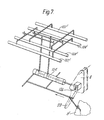
- the spool valve 104 is designed to supply pressurized air through internal ducts in the casing 3' (see Figure 7) to provide a first set of conditions in said cylinders, before actuation of the splicer, in which the pistons 110, 110' within the inner bores on each side of the casing 3' are positioned at their foremost extent of their travels within the respective bores and the pistons 109, 109' within the outer bores on each side of the casing 3' are positioned at their rearmost extent of their travels in the respective bores.
- the spool valve 104 is actuated to provide a second set of conditions in said cylinders in which each piston is displaced to the other end of its respective bore.
- the pistons and their extensions are dimensioned such that when they are in their rearmost positions in their respective bores their extensions extend slightly forward of the aforesaid plane 113 and when the pistons are in their foremost positions the ends of their respective extensions adjoining the pneumatically operative parts of the respective pistons extend to positions which are behind the aforesaid plane.
- the extensions of the pairs of pistons in the adjacent bores are arranged so that their mutually facing sides are spaced apart only sufficiently to admit and grip a thread. These sides are provided with friction surfaces.
- the arrangement is such that on each side of the housing a forward-facing, vertical, open slot is provided between the respective two extensions of the pistons, the face of the slot being slightly forward of said' plane 113 containing the splicing chamber.
- the running portions of the threads are inserted, care being taken to ensure that the said running threads are placed in the splicer from the appropriate directions for the operation which is to follow.
- the pneumatic connections between the second spool valve 104 and the cylinders 107, 107', 108, 108' and the pneumatic and the mechanical connections between the said second spool valve and corresponding elements on the casing 3' of the splicer are shown diagramati- cally in Figure 7.
- the air passages indicated therein are formed by drillings in the walls of appendages 101, 102 and added portion 103 of the casing.
Landscapes
- Spinning Or Twisting Of Yarns (AREA)
- Yarns And Mechanical Finishing Of Yarns Or Ropes (AREA)
- Actuator (AREA)
Priority Applications (1)
| Application Number | Priority Date | Filing Date | Title |
|---|---|---|---|
| AT85308931T ATE37014T1 (de) | 1984-12-10 | 1985-12-09 | Geraet zum pneumatischen spleissen von faeden. |
Applications Claiming Priority (2)
| Application Number | Priority Date | Filing Date | Title |
|---|---|---|---|
| GB08431093A GB2168397A (en) | 1984-12-10 | 1984-12-10 | Pneumatic yarn splicing equipment |
| GB8431093 | 1984-12-10 |
Publications (2)
| Publication Number | Publication Date |
|---|---|
| EP0186362A1 true EP0186362A1 (de) | 1986-07-02 |
| EP0186362B1 EP0186362B1 (de) | 1988-09-07 |
Family
ID=10570939
Family Applications (1)
| Application Number | Title | Priority Date | Filing Date |
|---|---|---|---|
| EP85308931A Expired EP0186362B1 (de) | 1984-12-10 | 1985-12-09 | Gerät zum pneumatischen Spleissen von Fäden |
Country Status (6)
| Country | Link |
|---|---|
| US (1) | US4751813A (de) |
| EP (1) | EP0186362B1 (de) |
| JP (1) | JPS61140475A (de) |
| AT (1) | ATE37014T1 (de) |
| DE (1) | DE3564797D1 (de) |
| GB (1) | GB2168397A (de) |
Cited By (2)
| Publication number | Priority date | Publication date | Assignee | Title |
|---|---|---|---|---|
| ITMO20090182A1 (it) * | 2009-07-15 | 2011-01-16 | Marco Turchi | Dispositivo autonomo per la giunzione di fili o filati tessili |
| CN103569799A (zh) * | 2012-07-05 | 2014-02-12 | 美斯丹(意大利)公司 | 通过压缩气体和液体连接纺线或纱线的设备及用于向该设备供应液体的装置 |
Families Citing this family (7)
| Publication number | Priority date | Publication date | Assignee | Title |
|---|---|---|---|---|
| US5357740A (en) * | 1991-07-09 | 1994-10-25 | Darron Moreland | Air splicing device and method |
| US6185922B1 (en) * | 1999-01-26 | 2001-02-13 | Williams Specialty Company | Air entanglement yarn splicer |
| BRPI0810567B1 (pt) | 2007-04-23 | 2020-05-05 | New Power Concepts Llc | máquina de ciclo stirling |
| US8763391B2 (en) | 2007-04-23 | 2014-07-01 | Deka Products Limited Partnership | Stirling cycle machine |
| US9441575B2 (en) * | 2008-04-25 | 2016-09-13 | New Power Concepts Llc | Thermal energy recovery system |
| GB2523164B (en) * | 2014-02-13 | 2019-05-01 | Gtw Developments Ltd | A fibre splicer and method for splicing fibres |
| EP3636571A1 (de) | 2018-10-12 | 2020-04-15 | Heberlein AG | Spleissgerät zur verspleissung von garn und verfahren zum herstellen eines spleissgeräts |
Citations (3)
| Publication number | Priority date | Publication date | Assignee | Title |
|---|---|---|---|---|
| US3984971A (en) * | 1975-02-24 | 1976-10-12 | Allied Chemical Corporation | Lid for pneumatic yarn splicer |
| GB1469256A (en) * | 1973-10-31 | 1977-04-06 | Fiber Industries Inc | Yarn splicing apparatus and method |
| GB2081328A (en) * | 1980-06-13 | 1982-02-17 | Mesdan Spa | Splicing textile yarns by intermingling component fibres with compressed air |
Family Cites Families (5)
| Publication number | Priority date | Publication date | Assignee | Title |
|---|---|---|---|---|
| US3306020A (en) * | 1966-07-05 | 1967-02-28 | Spunize Company Of America Inc | Method and apparatus for splicing yarn |
| US3477217A (en) * | 1968-12-05 | 1969-11-11 | Allied Chem | Automatic yarn splicer |
| GB2068033B (en) * | 1980-01-19 | 1984-09-19 | Reiners Verwaltungs Gmbh | Thread splicing device |
| CS564881A2 (en) * | 1980-08-02 | 1991-02-12 | Schlafhorst & Co W | Method of textile threads connecting and entwining device for realization of this method |
| CH660722A5 (de) * | 1982-11-12 | 1987-06-15 | Schweiter Ag Maschf | Verfahren und vorrichtung zum spleissen von zwei garnenden. |
-
1984
- 1984-12-10 GB GB08431093A patent/GB2168397A/en not_active Withdrawn
-
1985
- 1985-12-06 US US06/806,273 patent/US4751813A/en not_active Expired - Fee Related
- 1985-12-09 EP EP85308931A patent/EP0186362B1/de not_active Expired
- 1985-12-09 DE DE8585308931T patent/DE3564797D1/de not_active Expired
- 1985-12-09 AT AT85308931T patent/ATE37014T1/de not_active IP Right Cessation
- 1985-12-10 JP JP60278849A patent/JPS61140475A/ja active Pending
Patent Citations (3)
| Publication number | Priority date | Publication date | Assignee | Title |
|---|---|---|---|---|
| GB1469256A (en) * | 1973-10-31 | 1977-04-06 | Fiber Industries Inc | Yarn splicing apparatus and method |
| US3984971A (en) * | 1975-02-24 | 1976-10-12 | Allied Chemical Corporation | Lid for pneumatic yarn splicer |
| GB2081328A (en) * | 1980-06-13 | 1982-02-17 | Mesdan Spa | Splicing textile yarns by intermingling component fibres with compressed air |
Cited By (4)
| Publication number | Priority date | Publication date | Assignee | Title |
|---|---|---|---|---|
| ITMO20090182A1 (it) * | 2009-07-15 | 2011-01-16 | Marco Turchi | Dispositivo autonomo per la giunzione di fili o filati tessili |
| WO2011007243A1 (en) * | 2009-07-15 | 2011-01-20 | Marco Turchi | Independent device for joining textile threads or yarns |
| CN103569799A (zh) * | 2012-07-05 | 2014-02-12 | 美斯丹(意大利)公司 | 通过压缩气体和液体连接纺线或纱线的设备及用于向该设备供应液体的装置 |
| CN103569799B (zh) * | 2012-07-05 | 2017-03-01 | 美斯丹(意大利)公司 | 液体供应装置以及包含该装置的设备 |
Also Published As
| Publication number | Publication date |
|---|---|
| ATE37014T1 (de) | 1988-09-15 |
| EP0186362B1 (de) | 1988-09-07 |
| JPS61140475A (ja) | 1986-06-27 |
| DE3564797D1 (en) | 1988-10-13 |
| US4751813A (en) | 1988-06-21 |
| GB2168397A (en) | 1986-06-18 |
Similar Documents
| Publication | Publication Date | Title |
|---|---|---|
| US4751813A (en) | Pneumatic yarn splicing equipment | |
| US2652949A (en) | Dispenser with spring pressed follower | |
| KR101490672B1 (ko) | 유압 구동식 프레스 장치 및 설비물의 프레스 방법 | |
| US4433569A (en) | Crimping tongs | |
| JPS5848408B2 (ja) | タバネケ−ブルジドウトリツケコウグ | |
| JPS5810282B2 (ja) | ヒモニチヨウリヨクオカケセツダンスルタメノコウグ | |
| US5636444A (en) | Cutting device with frictional brake having a servo device with switching device for cancelling the braking effect | |
| US4072069A (en) | Wire stripping tools | |
| US4192358A (en) | Air powered installation of fasteners | |
| US5078374A (en) | Machine for cutting and folding a printed paper strip | |
| US3269223A (en) | Fluid operated hand tool | |
| US4243257A (en) | Gripper mechanism | |
| CA1196892A (en) | Jaw assembly for blind riveting | |
| US1969205A (en) | Material discharge gun | |
| JPH06312798A (ja) | 手で操作される作動装置 | |
| EP0007699B1 (de) | Gerät zum Abisolieren eines Drahtes | |
| US5279593A (en) | Trocar sleeve | |
| EP0227370A2 (de) | Pneumatische Spleissvorrichtung mit Faden-Verdrillungseinrichtung | |
| US5509194A (en) | Power crimping tool for tape feed products | |
| US3026520A (en) | Power operated c-ring clinching tool | |
| CS197262B2 (en) | Device for slacken the ropes | |
| US4112976A (en) | Improvements in or relating to controls for hydraulic valves | |
| JP4187969B2 (ja) | 胴に胴張りを圧着するための装置 | |
| US4463548A (en) | Pivotable suction tube for taking up a yarn from a bobbin | |
| IL43807A (en) | Plier for closing packaging envelopes |
Legal Events
| Date | Code | Title | Description |
|---|---|---|---|
| PUAI | Public reference made under article 153(3) epc to a published international application that has entered the european phase |
Free format text: ORIGINAL CODE: 0009012 |
|
| AK | Designated contracting states |
Kind code of ref document: A1 Designated state(s): AT BE CH DE FR GB IT LI |
|
| 17P | Request for examination filed |
Effective date: 19861105 |
|
| 17Q | First examination report despatched |
Effective date: 19870402 |
|
| GRAA | (expected) grant |
Free format text: ORIGINAL CODE: 0009210 |
|
| AK | Designated contracting states |
Kind code of ref document: B1 Designated state(s): AT BE CH DE FR GB IT LI |
|
| PG25 | Lapsed in a contracting state [announced via postgrant information from national office to epo] |
Ref country code: AT Effective date: 19880907 |
|
| REF | Corresponds to: |
Ref document number: 37014 Country of ref document: AT Date of ref document: 19880915 Kind code of ref document: T |
|
| REF | Corresponds to: |
Ref document number: 3564797 Country of ref document: DE Date of ref document: 19881013 |
|
| ET | Fr: translation filed | ||
| ITF | It: translation for a ep patent filed | ||
| PGFP | Annual fee paid to national office [announced via postgrant information from national office to epo] |
Ref country code: FR Payment date: 19881213 Year of fee payment: 4 Ref country code: AT Payment date: 19881213 Year of fee payment: 4 |
|
| PGFP | Annual fee paid to national office [announced via postgrant information from national office to epo] |
Ref country code: DE Payment date: 19890131 Year of fee payment: 4 |
|
| PLBE | No opposition filed within time limit |
Free format text: ORIGINAL CODE: 0009261 |
|
| STAA | Information on the status of an ep patent application or granted ep patent |
Free format text: STATUS: NO OPPOSITION FILED WITHIN TIME LIMIT |
|
| 26N | No opposition filed | ||
| PG25 | Lapsed in a contracting state [announced via postgrant information from national office to epo] |
Ref country code: GB Effective date: 19891209 |
|
| ITTA | It: last paid annual fee | ||
| PG25 | Lapsed in a contracting state [announced via postgrant information from national office to epo] |
Ref country code: LI Effective date: 19891231 Ref country code: CH Effective date: 19891231 Ref country code: BE Effective date: 19891231 |
|
| BERE | Be: lapsed |
Owner name: PENTWYN PRECISION LTD Effective date: 19891231 |
|
| GBPC | Gb: european patent ceased through non-payment of renewal fee | ||
| PG25 | Lapsed in a contracting state [announced via postgrant information from national office to epo] |
Ref country code: FR Effective date: 19900831 |
|
| REG | Reference to a national code |
Ref country code: CH Ref legal event code: PL |
|
| PG25 | Lapsed in a contracting state [announced via postgrant information from national office to epo] |
Ref country code: DE Effective date: 19900901 |
|
| REG | Reference to a national code |
Ref country code: FR Ref legal event code: ST |