EP0186413A2 - Einrichtung zum Spritzgiessen von Kunststoffen - Google Patents
Einrichtung zum Spritzgiessen von Kunststoffen Download PDFInfo
- Publication number
- EP0186413A2 EP0186413A2 EP85309179A EP85309179A EP0186413A2 EP 0186413 A2 EP0186413 A2 EP 0186413A2 EP 85309179 A EP85309179 A EP 85309179A EP 85309179 A EP85309179 A EP 85309179A EP 0186413 A2 EP0186413 A2 EP 0186413A2
- Authority
- EP
- European Patent Office
- Prior art keywords
- mould
- injection
- supply
- conduit
- mouldable
- Prior art date
- Legal status (The legal status is an assumption and is not a legal conclusion. Google has not performed a legal analysis and makes no representation as to the accuracy of the status listed.)
- Withdrawn
Links
- 238000001746 injection moulding Methods 0.000 title claims abstract description 8
- 239000004033 plastic Substances 0.000 title claims description 12
- 229920003023 plastic Polymers 0.000 title claims description 12
- 239000000463 material Substances 0.000 claims abstract description 45
- 238000002347 injection Methods 0.000 claims abstract description 27
- 239000007924 injection Substances 0.000 claims abstract description 27
- 238000000926 separation method Methods 0.000 claims abstract description 7
- 238000010438 heat treatment Methods 0.000 claims description 20
- 239000002184 metal Substances 0.000 claims description 3
- 238000000465 moulding Methods 0.000 description 5
- 208000015943 Coeliac disease Diseases 0.000 description 4
- 230000015572 biosynthetic process Effects 0.000 description 2
- 238000007711 solidification Methods 0.000 description 2
- 230000008023 solidification Effects 0.000 description 2
- 241000218657 Picea Species 0.000 description 1
- 229910000831 Steel Inorganic materials 0.000 description 1
- 239000000654 additive Substances 0.000 description 1
- 230000005540 biological transmission Effects 0.000 description 1
- 238000004140 cleaning Methods 0.000 description 1
- 238000001816 cooling Methods 0.000 description 1
- 230000000694 effects Effects 0.000 description 1
- 239000008187 granular material Substances 0.000 description 1
- 239000000155 melt Substances 0.000 description 1
- 238000000034 method Methods 0.000 description 1
- 239000012768 molten material Substances 0.000 description 1
- 229920000642 polymer Polymers 0.000 description 1
- 230000002028 premature Effects 0.000 description 1
- 239000002994 raw material Substances 0.000 description 1
- 239000010959 steel Substances 0.000 description 1
- 239000002699 waste material Substances 0.000 description 1
Images

Classifications
-
- B—PERFORMING OPERATIONS; TRANSPORTING
- B29—WORKING OF PLASTICS; WORKING OF SUBSTANCES IN A PLASTIC STATE IN GENERAL
- B29C—SHAPING OR JOINING OF PLASTICS; SHAPING OF MATERIAL IN A PLASTIC STATE, NOT OTHERWISE PROVIDED FOR; AFTER-TREATMENT OF THE SHAPED PRODUCTS, e.g. REPAIRING
- B29C45/00—Injection moulding, i.e. forcing the required volume of moulding material through a nozzle into a closed mould; Apparatus therefor
- B29C45/17—Component parts, details or accessories; Auxiliary operations
- B29C45/26—Moulds
- B29C45/27—Sprue channels ; Runner channels or runner nozzles
- B29C45/2735—Sprue channels ; Runner channels or runner nozzles for non-coaxial gates, e.g. for edge gates
-
- B—PERFORMING OPERATIONS; TRANSPORTING
- B29—WORKING OF PLASTICS; WORKING OF SUBSTANCES IN A PLASTIC STATE IN GENERAL
- B29C—SHAPING OR JOINING OF PLASTICS; SHAPING OF MATERIAL IN A PLASTIC STATE, NOT OTHERWISE PROVIDED FOR; AFTER-TREATMENT OF THE SHAPED PRODUCTS, e.g. REPAIRING
- B29C45/00—Injection moulding, i.e. forcing the required volume of moulding material through a nozzle into a closed mould; Apparatus therefor
- B29C45/17—Component parts, details or accessories; Auxiliary operations
- B29C45/26—Moulds
- B29C45/27—Sprue channels ; Runner channels or runner nozzles
- B29C45/30—Flow control means disposed within the sprue channel, e.g. "torpedo" construction
Definitions
- injection moulding apparatus comprises means for the supply of plastics material at room temperature, usually in the form of granules means for feeding the raw material together with any necessary additives to a heating chamber whereby the material is heated to form a melt capable of being moulded and it is then transported under the influence of, for example, a transport screw via a heated supply conduit to a mould.
- the mould is usually a multi-part mould having at least two principal parts, all the parts when assembled, defining a mould cavity having the shape and configuration of the article to be moulded.
- the material is usually supplied to the mould cavity by means of the heated conduit and heating means is provided within at least part of the mould housing itself to prevent premature cooling of the plastics material prior to injection into the mould cavity.
- the moulding operation is usually effected by a stroke of an injection piston or ram, and mouldable material is injected into the mould cavity substantially parallel to the direction which the mould is subsequently split.
- the material within the mould is allowed to cool until it has solidified sufficiently to retain its moulded shape.
- the mould is then split in a direction such that the moulded article can be withdrawn. A first part of the mould not connected with the material supply system is withdrawn and the article is then eased out of the mould for subsequent cleaning up.
- a difficulty with this type of.apparatus is that on solidification a part of the material still within the injection conduit within the mould also solidifies. On withdrawal of the article from the second mould part which remains connected with the plastics supply, this solidified portion known as a sprue is also withdrawn leaving an imperfectly.moulded article. It follows, therefore, that the surplus comprising the "sprue" has to be removed before the moulded article is complete.
- injection moulding appartus comprising:
- the mouldable material is preferably a plastics material and the means for supply preferably includes heating means for forming an injectable melt of said plastics material.
- the point or points of injection of said material into the mould is preferably in the side of the mould when considered with respect to the direction of separation of the first and second mould parts.
- the supply means may comprise a conduit of substantially circular cross-section, juxtaposed a heating member for the supply of heat to the mouldable material to maintain said material at a moulding temperature.
- the heating element may be adapted to supply heat to material in the conduits within the mould body.
- the supply conduit for the mouldable material is preferably of circular cross-section at the point of injection into the mould cavity.
- the heating element extending into the conduit within the mould body is preferably a metal element in heat conducting contact with the heat member of the supply means.
- any sprue that does form is removed on withdrawal of the moulded article from the mould.
- the molten material of the present invention can in one embodiment of the invention flow in separate channels right up to the injection gate and this has the advantage of providing substantially uniform flow of polymer having a substantially uniform temperature distribution.
- the injection apparatus of the present invention provides for a more compact volume of the injection head and thus provides apparatus more suitable for multi-head injection equipment.
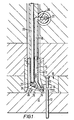
- the mould comprises a first mould member 10 having a first insert 11 and a second withdrawable insert 12 secured with a withdrawable body ,13, the mould components serving to define a mould cavity 14 which as viewed in Figure 1 has a general cross section in the form of a letter 'H'.
- the mould body 10 carries on one side thereof an injection gate 15 which is supplied with molten plastics material by means of conduit 16 which supplies plastics material in the direction shown in the arrow to a further conduit 17 whereby the plastics material is mixed between conduits 16 and 17 for supply to gate 15.
- the supply of mouldable material is provided by an upward extension 18 of conduit 16 from material supply conduit 20.
- the temperature of the material as supplied from conduit 20 via conduit 18 to conduit 16 in the mould head is maintained by means of heating elements 21 and 22 respectively.
- Heating element 21 is substantially parallel with conduits 18 and 16 respectively and extends downwardly into the moulding head to terminate at its lower end 23 in juxtaposition to mould head heating means indicated generally at 24.
- Mould head heating means comprises a steel rod 25 having at its first end a head 26 and at a second end a point 27 which is juxtaposed mould gate 15.
- housing 24 which is also of heat conducting metal and is heat conducting contact with the lower end at 23 of heating element 22, the arrangement being such that mouldable material passing down conduit 16 is maintained at mouldable temperature by its juxtaposition with heating element 22 until it passes into the area of rod 25 and then passes again into the area 17 where towards the mould gate 15 the material is still subject to heating by means of the extremity 27 of rod 25.
- Figure 2 shows a variation of the apparatus as applied to a two-head injection moulding apparatus in accordance with the present invention.
Landscapes
- Engineering & Computer Science (AREA)
- Manufacturing & Machinery (AREA)
- Mechanical Engineering (AREA)
- Injection Moulding Of Plastics Or The Like (AREA)
- Moulds For Moulding Plastics Or The Like (AREA)
Applications Claiming Priority (2)
| Application Number | Priority Date | Filing Date | Title |
|---|---|---|---|
| GB8432451 | 1984-12-21 | ||
| GB848432451A GB8432451D0 (en) | 1984-12-21 | 1984-12-21 | Injection moulding of plastics |
Publications (2)
| Publication Number | Publication Date |
|---|---|
| EP0186413A2 true EP0186413A2 (de) | 1986-07-02 |
| EP0186413A3 EP0186413A3 (de) | 1988-04-27 |
Family
ID=10571626
Family Applications (1)
| Application Number | Title | Priority Date | Filing Date |
|---|---|---|---|
| EP85309179A Withdrawn EP0186413A3 (de) | 1984-12-21 | 1985-12-17 | Einrichtung zum Spritzgiessen von Kunststoffen |
Country Status (2)
| Country | Link |
|---|---|
| EP (1) | EP0186413A3 (de) |
| GB (1) | GB8432451D0 (de) |
Cited By (22)
| Publication number | Priority date | Publication date | Assignee | Title |
|---|---|---|---|---|
| EP0312092A3 (de) * | 1987-10-16 | 1990-03-28 | Mold-Masters Limited | Spritzgiessdüse mit einem geerdeten Heizelement, hartgelötet in einem spitzen Ende |
| EP0406011A1 (de) * | 1989-06-30 | 1991-01-02 | Polyplastics Co. Ltd. | Aerosoldose |
| US5009587A (en) * | 1987-10-31 | 1991-04-23 | Schottli Ag | Injection molding machine for making tubular workpieces from plastic material |
| WO1991013742A1 (en) * | 1990-03-15 | 1991-09-19 | Seiki Corporation Co., Ltd. | Improved side gate type mold arrangement with pointed heat-generating module |
| EP0447573A1 (de) * | 1990-03-17 | 1991-09-25 | Dipl.-Ing. Herbert Günther Gesellschaft mbH | Heisskanaldüse |
| EP0501284A3 (en) * | 1991-02-27 | 1993-02-03 | Jobst Ulrich Gellert | Injection molding probe with a longitudinal thermocouple bore and off center heating element |
| EP0535616A1 (de) * | 1991-10-01 | 1993-04-07 | Jobst Ulrich Gellert | Spritzgiessvorrichtung mit Torpedo mit winklig angeordneter Spitze |
| EP0528316A3 (en) * | 1991-08-16 | 1993-04-28 | Dipl.-Ing. Herbert Guenther Gesellschaft Mbh | Hot runner nozzle |
| US5330349A (en) * | 1992-03-30 | 1994-07-19 | Sony Corporation | Injection mold having a cylindrical down gate |
| US5378139A (en) * | 1993-09-07 | 1995-01-03 | Husky Injection Molding Systems Ltd. | Hook nozzle for inside gated mold |
| EP0657269A1 (de) * | 1993-12-01 | 1995-06-14 | Jobst Ulrich Gellert | Spritzgiessvorrichtung mit senkrechten Anschnitten mit heisser Spitze |
| US5711910A (en) * | 1995-11-16 | 1998-01-27 | Tulip Corporation | Method for making a stackable container formed by a nozzle having an offset gate |
| EP1380400A1 (de) * | 2002-07-10 | 2004-01-14 | Männer, Otto Heisskanalsysteme GmbH & Co. KG | Spritzgiessdüse mit Nadelverschluss und seitlichen Austrittsöffnungen |
| EP1524091A3 (de) * | 2003-09-29 | 2006-03-01 | Hans Schreck | Vorrichtung zum Anspritzen von insbesondere Kunststoffformteilen |
| US7396226B2 (en) | 2006-03-10 | 2008-07-08 | Mold-Masters (2007) Limited | Nozzle sealing assembly |
| US7410353B2 (en) | 2004-10-20 | 2008-08-12 | Mold-Masters (2007) Limited | Edge gated injection molding apparatus |
| US7658605B2 (en) | 2006-12-29 | 2010-02-09 | Mold-Masters (2007) Limited | Edge gated injection molding apparatus |
| US7658606B2 (en) | 2006-12-22 | 2010-02-09 | Mold-Masters (2007) Limited | Edge gated injection molding apparatus |
| US7794228B2 (en) | 2008-04-29 | 2010-09-14 | Mold-Masters (2007) Limited | Injection molding apparatus having an edge-gated runnerless nozzle |
| DE202009004786U1 (de) | 2009-05-06 | 2010-09-23 | EWIKON Heißkanalsysteme GmbH & Co. KG | Heißkanaldüse zur Seitenanspritzung |
| US8282387B2 (en) | 2008-04-11 | 2012-10-09 | Ewikon Heisskanalsysteme Gmbh & Co Kg | Hot runner nozzle for lateral spraying |
| US11548195B2 (en) | 2020-10-22 | 2023-01-10 | Mold-Masters (2007) Limited | Angle gating injection molding apparatus |
Family Cites Families (4)
| Publication number | Priority date | Publication date | Assignee | Title |
|---|---|---|---|---|
| CH449953A (de) * | 1966-09-02 | 1968-01-15 | Segmueller Ag | Einspritzdüse für Heisskanal-Spritzgusswerkzeug |
| JPS5227181B1 (de) * | 1971-02-17 | 1977-07-19 | ||
| US4304544A (en) * | 1974-10-21 | 1981-12-08 | Fast Heat Element Mfg. Co., Inc. | Electrically heated nozzles and nozzle systems |
| EP0058004B1 (de) * | 1981-01-30 | 1985-07-17 | SORENSEN, Jens Ole | Kunststoff-Mehrfachspritzgiessen mit geneigtem Heisskanal |
-
1984
- 1984-12-21 GB GB848432451A patent/GB8432451D0/en active Pending
-
1985
- 1985-12-17 EP EP85309179A patent/EP0186413A3/de not_active Withdrawn
Cited By (33)
| Publication number | Priority date | Publication date | Assignee | Title |
|---|---|---|---|---|
| EP0312092A3 (de) * | 1987-10-16 | 1990-03-28 | Mold-Masters Limited | Spritzgiessdüse mit einem geerdeten Heizelement, hartgelötet in einem spitzen Ende |
| US5009587A (en) * | 1987-10-31 | 1991-04-23 | Schottli Ag | Injection molding machine for making tubular workpieces from plastic material |
| EP0406011A1 (de) * | 1989-06-30 | 1991-01-02 | Polyplastics Co. Ltd. | Aerosoldose |
| US5083684A (en) * | 1989-06-30 | 1992-01-28 | Polyplastics Co., Ltd. | Injection-molded lid for an aerosol container |
| WO1991013742A1 (en) * | 1990-03-15 | 1991-09-19 | Seiki Corporation Co., Ltd. | Improved side gate type mold arrangement with pointed heat-generating module |
| EP0447573A1 (de) * | 1990-03-17 | 1991-09-25 | Dipl.-Ing. Herbert Günther Gesellschaft mbH | Heisskanaldüse |
| EP0501284A3 (en) * | 1991-02-27 | 1993-02-03 | Jobst Ulrich Gellert | Injection molding probe with a longitudinal thermocouple bore and off center heating element |
| EP0528316A3 (en) * | 1991-08-16 | 1993-04-28 | Dipl.-Ing. Herbert Guenther Gesellschaft Mbh | Hot runner nozzle |
| CN1038234C (zh) * | 1991-10-01 | 1998-05-06 | 乔布斯特·乌尔里克·盖勒特 | 具有斜角顶尖探头的注射成型装置 |
| DE4232675B4 (de) * | 1991-10-01 | 2005-09-29 | Gellert, Jobst Ulrich, Georgetown | Angußdüse für eine Spritzgießvorrichtung mit einer an ihrem Ende winklig verlaufenden Heizsonde |
| EP0535616A1 (de) * | 1991-10-01 | 1993-04-07 | Jobst Ulrich Gellert | Spritzgiessvorrichtung mit Torpedo mit winklig angeordneter Spitze |
| US5330349A (en) * | 1992-03-30 | 1994-07-19 | Sony Corporation | Injection mold having a cylindrical down gate |
| US5378139A (en) * | 1993-09-07 | 1995-01-03 | Husky Injection Molding Systems Ltd. | Hook nozzle for inside gated mold |
| EP0657269A1 (de) * | 1993-12-01 | 1995-06-14 | Jobst Ulrich Gellert | Spritzgiessvorrichtung mit senkrechten Anschnitten mit heisser Spitze |
| US5711910A (en) * | 1995-11-16 | 1998-01-27 | Tulip Corporation | Method for making a stackable container formed by a nozzle having an offset gate |
| US7322817B2 (en) | 2002-07-10 | 2008-01-29 | Otto Manner Innovation Gmbh | Injection molding nozzle for plastic with at least two outlet openings |
| EP1380400A1 (de) * | 2002-07-10 | 2004-01-14 | Männer, Otto Heisskanalsysteme GmbH & Co. KG | Spritzgiessdüse mit Nadelverschluss und seitlichen Austrittsöffnungen |
| EP1524091A3 (de) * | 2003-09-29 | 2006-03-01 | Hans Schreck | Vorrichtung zum Anspritzen von insbesondere Kunststoffformteilen |
| CN100532061C (zh) * | 2003-09-29 | 2009-08-26 | H·施雷克 | 特别的塑料成形的喷射装置 |
| US7303384B2 (en) | 2003-09-29 | 2007-12-04 | Hans Schreck | Device for spraying-on of especially plastic mouldings |
| US7410353B2 (en) | 2004-10-20 | 2008-08-12 | Mold-Masters (2007) Limited | Edge gated injection molding apparatus |
| US7396226B2 (en) | 2006-03-10 | 2008-07-08 | Mold-Masters (2007) Limited | Nozzle sealing assembly |
| US7658606B2 (en) | 2006-12-22 | 2010-02-09 | Mold-Masters (2007) Limited | Edge gated injection molding apparatus |
| US7658605B2 (en) | 2006-12-29 | 2010-02-09 | Mold-Masters (2007) Limited | Edge gated injection molding apparatus |
| US8282387B2 (en) | 2008-04-11 | 2012-10-09 | Ewikon Heisskanalsysteme Gmbh & Co Kg | Hot runner nozzle for lateral spraying |
| US7794228B2 (en) | 2008-04-29 | 2010-09-14 | Mold-Masters (2007) Limited | Injection molding apparatus having an edge-gated runnerless nozzle |
| US8202082B2 (en) | 2008-04-29 | 2012-06-19 | Mold-Masters (2007) Limited | Injection molding apparatus having an edge-gated runnerless nozzle including a bracing component and a securing component |
| US8206145B2 (en) | 2008-04-29 | 2012-06-26 | Mold-Masters (2007) Limited | Injection molding apparatus having an edge-gated runnerless nozzle |
| US8210842B2 (en) | 2008-04-29 | 2012-07-03 | Mold-Masters (2007) Limited | Injection molding apparatus having an edge-gated runnerless nozzle including a bracing portion and a securing component |
| US8475155B2 (en) | 2008-04-29 | 2013-07-02 | Mold-Masters (2007) Limited | Injection molding nozzle having a bracing component and a securing component |
| DE202009004786U1 (de) | 2009-05-06 | 2010-09-23 | EWIKON Heißkanalsysteme GmbH & Co. KG | Heißkanaldüse zur Seitenanspritzung |
| US8899963B2 (en) | 2009-05-06 | 2014-12-02 | Ewikon Heisskanalsysteme Gmbh | Hot nozzle for lateral spraying |
| US11548195B2 (en) | 2020-10-22 | 2023-01-10 | Mold-Masters (2007) Limited | Angle gating injection molding apparatus |
Also Published As
| Publication number | Publication date |
|---|---|
| GB8432451D0 (en) | 1985-02-06 |
| EP0186413A3 (de) | 1988-04-27 |
Similar Documents
| Publication | Publication Date | Title |
|---|---|---|
| EP0186413A2 (de) | Einrichtung zum Spritzgiessen von Kunststoffen | |
| EP0013154B1 (de) | Verfahren und Vorrichtung zum angusslosen Spritzprägen von wärmehärtenden Massen | |
| HK1049636A1 (en) | Hot-chamber high pressure diecasting method, die set and sprue insert-set for use in the same | |
| JPH0337494B2 (de) | ||
| EP0172536B1 (de) | Verfahren zum Spritzgiessen für geschmolzenen Kunststoff | |
| US5460508A (en) | Resin molding method and apparatus | |
| US3903956A (en) | Die casting machine with parting line feed | |
| EP0068614B1 (de) | Vorrichtung und Verfahren zum angussfreien Spritzpressen wärmehärtbarer Materialien | |
| US3374502A (en) | Sprue bushing and nozzle assembly | |
| EP0053450B1 (de) | Verfahren zur Herstellung von Kathoden für Natrium-Schwefel-Zellen | |
| US4443175A (en) | Apparatus and method for runnerless transfer molding of thermoset compounds | |
| DE2542875A1 (de) | Verfahren zum angusslosen spritzen von thermoplastteilen | |
| JPH06210685A (ja) | フローモールド成形方法 | |
| DE4035194C2 (de) | ||
| CN210415335U (zh) | 热固性塑料注射成型模具 | |
| US4447386A (en) | Process for runnerless injection - compression molding of thermosetting materials | |
| KR20190083107A (ko) | 금형 | |
| SU1577999A1 (ru) | Литьева форма дл изготовлени полимерных изделий | |
| JP3081956B2 (ja) | カセット式射出成形金型装置 | |
| AU764102B2 (en) | Hot sprue system for diecasting | |
| JPH06238698A (ja) | 中空成形体の成形装置 | |
| JPH0582520U (ja) | 射出成形用金型 | |
| SU1201051A1 (ru) | Способ лить под давлением и пресс-форма дл его осуществлени | |
| JPS6235823A (ja) | 射出成形方法 | |
| JPH01118422A (ja) | 射出圧縮成形金型 |
Legal Events
| Date | Code | Title | Description |
|---|---|---|---|
| PUAI | Public reference made under article 153(3) epc to a published international application that has entered the european phase |
Free format text: ORIGINAL CODE: 0009012 |
|
| AK | Designated contracting states |
Kind code of ref document: A2 Designated state(s): AT BE CH DE FR GB IT LI LU NL SE |
|
| PUAL | Search report despatched |
Free format text: ORIGINAL CODE: 0009013 |
|
| AK | Designated contracting states |
Kind code of ref document: A3 Designated state(s): AT BE CH DE FR GB IT LI LU NL SE |
|
| STAA | Information on the status of an ep patent application or granted ep patent |
Free format text: STATUS: THE APPLICATION IS DEEMED TO BE WITHDRAWN |
|
| 18D | Application deemed to be withdrawn |
Effective date: 19881028 |
|
| RIN1 | Information on inventor provided before grant (corrected) |
Inventor name: TANNER, MAX |