EP0186500B1 - Transmission continue hydrostatique - Google Patents
Transmission continue hydrostatique Download PDFInfo
- Publication number
- EP0186500B1 EP0186500B1 EP85309434A EP85309434A EP0186500B1 EP 0186500 B1 EP0186500 B1 EP 0186500B1 EP 85309434 A EP85309434 A EP 85309434A EP 85309434 A EP85309434 A EP 85309434A EP 0186500 B1 EP0186500 B1 EP 0186500B1
- Authority
- EP
- European Patent Office
- Prior art keywords
- cylinder
- motor
- transmission
- pump
- swashplate
- Prior art date
- Legal status (The legal status is an assumption and is not a legal conclusion. Google has not performed a legal analysis and makes no representation as to the accuracy of the status listed.)
- Expired - Lifetime
Links
- 230000005540 biological transmission Effects 0.000 title claims description 42
- 230000003068 static effect Effects 0.000 title claims description 6
- 239000012530 fluid Substances 0.000 description 9
- 230000002093 peripheral effect Effects 0.000 description 9
- 238000010276 construction Methods 0.000 description 2
- 230000008602 contraction Effects 0.000 description 2
- 230000000694 effects Effects 0.000 description 2
- 230000003247 decreasing effect Effects 0.000 description 1
Images

Classifications
-
- F—MECHANICAL ENGINEERING; LIGHTING; HEATING; WEAPONS; BLASTING
- F16—ENGINEERING ELEMENTS AND UNITS; GENERAL MEASURES FOR PRODUCING AND MAINTAINING EFFECTIVE FUNCTIONING OF MACHINES OR INSTALLATIONS; THERMAL INSULATION IN GENERAL
- F16H—GEARING
- F16H61/00—Control functions within control units of change-speed- or reversing-gearings for conveying rotary motion ; Control of exclusively fluid gearing, friction gearing, gearings with endless flexible members or other particular types of gearing
- F16H61/38—Control of exclusively fluid gearing
- F16H61/40—Control of exclusively fluid gearing hydrostatic
- F16H61/42—Control of exclusively fluid gearing hydrostatic involving adjustment of a pump or motor with adjustable output or capacity
- F16H61/421—Motor capacity control by electro-hydraulic control means, e.g. using solenoid valves
-
- F—MECHANICAL ENGINEERING; LIGHTING; HEATING; WEAPONS; BLASTING
- F16—ENGINEERING ELEMENTS AND UNITS; GENERAL MEASURES FOR PRODUCING AND MAINTAINING EFFECTIVE FUNCTIONING OF MACHINES OR INSTALLATIONS; THERMAL INSULATION IN GENERAL
- F16H—GEARING
- F16H39/00—Rotary fluid gearing using pumps and motors of the volumetric type, i.e. passing a predetermined volume of fluid per revolution
- F16H39/04—Rotary fluid gearing using pumps and motors of the volumetric type, i.e. passing a predetermined volume of fluid per revolution with liquid motor and pump combined in one unit
- F16H39/06—Rotary fluid gearing using pumps and motors of the volumetric type, i.e. passing a predetermined volume of fluid per revolution with liquid motor and pump combined in one unit pump and motor being of the same type
- F16H39/08—Rotary fluid gearing using pumps and motors of the volumetric type, i.e. passing a predetermined volume of fluid per revolution with liquid motor and pump combined in one unit pump and motor being of the same type each with one main shaft and provided with pistons reciprocating in cylinders
- F16H39/10—Rotary fluid gearing using pumps and motors of the volumetric type, i.e. passing a predetermined volume of fluid per revolution with liquid motor and pump combined in one unit pump and motor being of the same type each with one main shaft and provided with pistons reciprocating in cylinders with cylinders arranged around, and parallel or approximately parallel to the main axis of the gearing
- F16H39/14—Rotary fluid gearing using pumps and motors of the volumetric type, i.e. passing a predetermined volume of fluid per revolution with liquid motor and pump combined in one unit pump and motor being of the same type each with one main shaft and provided with pistons reciprocating in cylinders with cylinders arranged around, and parallel or approximately parallel to the main axis of the gearing with cylinders carried in rotary cylinder blocks or cylinder-bearing members
-
- F—MECHANICAL ENGINEERING; LIGHTING; HEATING; WEAPONS; BLASTING
- F16—ENGINEERING ELEMENTS AND UNITS; GENERAL MEASURES FOR PRODUCING AND MAINTAINING EFFECTIVE FUNCTIONING OF MACHINES OR INSTALLATIONS; THERMAL INSULATION IN GENERAL
- F16H—GEARING
- F16H61/00—Control functions within control units of change-speed- or reversing-gearings for conveying rotary motion ; Control of exclusively fluid gearing, friction gearing, gearings with endless flexible members or other particular types of gearing
- F16H61/38—Control of exclusively fluid gearing
- F16H61/40—Control of exclusively fluid gearing hydrostatic
- F16H61/42—Control of exclusively fluid gearing hydrostatic involving adjustment of a pump or motor with adjustable output or capacity
Definitions
- This invention relates to a static hydraulic pressure type continuously variable transmission, and more particularly to such a transmission in which a hydraulic closed circuit is formed between a swashplate type hydraulic pump and a swashplate type hydraulic motor, as disclosed for example in Japanese Patent Application Laid-Open No. 70968/82 and Japanese Patent Publication No. 38467/84.
- US-A-2844002 discloses in accordance with the preamble of claim 1 a static hydraulic pressure type continuously variable transmission comprising: a casing; a swashplate type hydraulic pump having a pump cylinder; a swashplate type hydraulic motor having a motor cylinder, the pump cylinder and the motor cylinder being integrally connected with each other on the same axis; a hydraulic closed circuit between said hydraulic pump and said hydraulic motor; and a transmission shaft rotatably supported on said casing.
- the present invention is characterised in that both said pump cylinder and said motor cylinder are supported on said transmission shaft, and an input member which directly drives the pump swashplate is mounted around said transmission shaft in relatively rotatable but axially immovable fashion, whereby thrust force generated from said hydraulic pump is received and supported by said transmission shaft.
- a non-rotatable motor swashplate anchor is mounted axially immovably on said transmission shaft and tiltably supports the motor swashplate, whereby thrust force generated by said hydraulic motor is received and supported by said transmission shaft, thus making a further contribution to reducing the weight and rigidity of the transmission casing.
- the said transmission shaft is the power output shaft of the transmission.
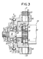
- the continuously variable transmission T comprises a swashplate type hydraulic pump P of a constant capacity type and a swashplate type hydraulic motor M of a variable capacity type, which are accommodated within a crank case 4 as a casing which carries the crank shaft 1.
- the hydraulic pump P comprises a cup-like input member 5 integrally provided with an output sprocket 2a of the primary reduction gear 2, a pump cylinder 7 relatively rotatably fitted in the inner peripheral wall of the input member 5 through a needle bearing 6, pump plungers 9, 9 ... slidably fitted in a plurality and odd-number of annularly disposed cylinder bores 8, 8 provided in the pump cylinder 7 so as to surround the rotary center thereof, and a pump swashplate 10 in contact with the outer ends of the pump plungers 9, 9 ...
- the back surface of the pump swashplate 10 is rotatably supported on the inner end wall of the input member 5 in an attitude inclined by a predetermined angle with respect to the axis of the pump cylinder 7 through a thrust roller bearing 11 so that when the input member 5 is rotated, the pump plungers 9, 9 ... are reciprocated to repeatedly effect suction and exhaust strokes.
- the back surface of the input member 5 is supported on a support sleeve 13 through a thrust roller bearing 12.
- the hydraulic motor M comprises a motor cylinder 17 coaxially and closely coupled to the pump cylinder 7, a support shaft 24 and an output shaft 25 integrally formed to central parts of both inner and outer ends of the motor cylinder 17 and extending in an axial direction, motor plungers 19, 19 ... respectively slidably fitted in a plurality and odd-number of annularly disposed cylinder bores 18, 18 ...
- a motor swashplate 20 in contact with outer ends of the motor plungers 19, 19 ..., a swashplate holder 22 for supporting the back surface of the motor swashplate 20 through a thrust roller bearing 21, and a swashplate anchor 23 for supporting the back surface of the swashplate holder 22.
- the motor swashplate 20 is tiltingly movable between an upright position at right angles to the axis of the motor cylinder 17 and a position inclined at a certain angle. In the inclined position, the motor plungers 19,19 ... are reciprocated upon rotation of the motor cylinder 17 to repeatedly effect expansion and contraction strokes.
- the aforesaid support shaft 24 extends through the central portion of the pump cylinder 7, with which a nut 26 is threadedly engaged whereby the pump cylinder 7 and the motor cylinder 17 are integrally connected to each other.
- the support shaft 24 further extends through the input member 5 and rotatably supports the input member 5 through a needle bearing 27.
- the support sleeve 13 is splined-fitted and secured by means of a nut 30.
- the support shaft 24 is rotatably supported on the crank case 4 through the support sleeve 13 and a roller bearing 31.
- the aforesaid output shaft 25 extends through the central portion of the motor swashplate 20, the swashplate holder 22 and the swashplate anchor 23, and a support sleeve 33 for supporting the back surface of the swashplate anchor 23 through a thrust roller bearing 32 is splined-fitted to the end of the shaft 25 and is secured by means of a nut 34 with an input sprocket 3a of the secondary reduction gear 3.
- the output shaft 25 is rotatably supported on the crank case 4 through the support sleeve 33 and a roller bearing 35.
- a spherical spline member 36 Secured to the support shaft 24 is a spherical spline member 36 in spline engagement with the inner peripheral surface of the pump swashplate 10 in a manner relatively tiltable in all directions
- a spherical spline member 37 secured to the output shaft 25 is a spherical spline member 37 in spline engagement with the inner peripheral surface of the motor swashplate 20 in a manner relatively tiltably in all directions.
- an annular high pressure oil passage 40 and an annular low pressure oil passage 41 to encircle the oil passage 40 are provided between the group of cylinder bores 8, 8 ... of the pump cylinder 7 and the group of cylinder bores 18, 18 ... of the motor cylinder 17, the high pressure oil passage 40 being communicated with the cylinder bores 8, 8 ... of the pump cylinder 7 through discharge valves 42, 42 ..., the low pressure oil passage 41 being likewise communicated with the cylinder bores 8, 8 ... through intake valves 43, 43 ... Accordingly, the discharge valves 42 and the intake valves 43 are respectively provided in the same number as that of the pump plungers 9, 9 ...
- the distribution valves 44, 44 ... which are of a spool type, are slidably fitted into valve holes 45, 45 ... radially provided in the motor cylinder 17 between the group of cylinder bores 18, 18 ... and the high and low pressure oil passages 40, 41, whereby when the valve 44 occupies the radial inward position in the valve hole 45, there is provided a communication between the corresponding cylinder bore 18 and high pressure oil passage 40 whilst the cylinder bore 18 is shut off from the low pressure oil passage 41, and when the valve 44 occupies the radial outward position in the valve hole 45, there is provided a communication between the corresponding cylinder bore 18 and low pressure oil passage 41 whilst the bore is cut off its communication with the high pressure oil passage 40.
- Valve springs 46, 46 ... for biasing the distribution valves 44, 44 .. radially outwardly are accommodated within the valve holes 45, 45 ... to control the distribution valves 44, 44 ..., and the inner peripheral surface of an eccentric ring 47 is engaged with the outer end of each distribution valve 44.
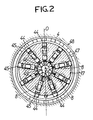
- the eccentric ring 47 is formed of an inner race of a ball bearing 48 snapped in and secured to the crank case 4, and as shown in FIG. 2, the ring 47 is installed at such a position that the center thereof is to be eccentric a predetermined distance ⁇ from the center of the motor cylinder 17 in a direction of the tilting axis 0 of the motor swashplate 20. Accordingly, when the motor cylinder rotates, each of the distribution valves 44 takes the stroke of 2 ⁇ which is twice the eccentric amount ⁇ of the eccentric ring 47, within the valve hole 45 and reciprocates between the aforesaid outward position and inward position.
- the distribution valve 44 also has a function to bring a replenishing oil passage 49 into communication with the low pressure oil passage 41 when the valve assumes the inward position in the valve hole 45.
- the replenishing oil passage 49 is provided in the central portion of the support shaft 24 and connected to the discharge port of a replenishing pump 50.
- the pump 50 is driven by the crank shaft 1 to supply oil stored in an oil reservoir 51 at the bottom of the crank case 4 to the oil passage 49 under relatively low pressure.
- an outer peripheral surface 20a of the motor swashplate 20 is formed into a spherical surface having its center at the tilting axis 0.
- a spherical recess 52 is formed in the front surface of the swashplate holder 22 so as to receive the motor swashplate 20 along with the thrust roller bearing 21.
- a back surface 22a of the swashplate holder 22 is formed in a circular surface about the tilting axis 0 of the motor swashplate 20, and a semi-cylindrical recess 53 is formed in the front surface of the swashplate anchor 23 so as to support the swashplate holder 22 rotatably about the tilting axis 0.
- This swashplate anchor 23 is connected to the crank case 4 through locating pins 54 so that the anchor may not be rotated about the output shaft 25.
- a pair of trunnion shafts 55, 55' aligned on the tilting axis 0 are integrally projected on both ends of the swashplate holder 22, the trunnion shafts 55, 55' being rotatably supported on the swashplate anchor 23 through needle bearings 56.
- the tilting axis 0 is defined by the trunnion shafts 55, 55'.
- An operating lever 57 is fixedly mounted on the outer end of one trunnion shaft 55.
- the swashplate holder 22 integral therewith When the trunnion shaft 55 is rotated by the operating lever 57, the swashplate holder 22 integral therewith also rotates and the latter can be tilted even during the rotation of the motor swashplate 20.
- the high pressure working fluid fed to the high pressure oil passage 40 is supplied to the cylinder bore 18 accommodating the motor plunger 19 in expansion stroke through the distribution valve 44 at the inward position whereas the working fluid within the cylinder bore 18 accommodating the motor plunger 19 in contraction stroke is discharged into the low pressure oil passage 41 through the distribution valve 44 at the outward position.
- the pump cylinder 7 and motor cylinder 17 are rotated by the sum of reaction torque received by the pump cylinder 7 from the pump swashplate 10 through the pump plungers 9 in exhaust stroke and reaction torque received by the motor cylinder 17 from the motor swashplate 20 through the motor plunger 19 in expansion stroke, which rotary torque is transmitted from the output shaft 25 to the secondary reduction gear 3.
- the speed change ratio can be changed from 1 to a required value.
- the motor swashplate 20 can be tilted from an upright position to an inclined position to thereby steplessly control the ratio from 1 to a certain value.
- the pump swashplate 10 and motor swashplate 20 receive the opposite thrust load from the group of pump plungers 9, 9 ... and the group of motor plungers 19, 19 ... respectively.
- the thrust load applied to the pump swashplate 10 is carried by the support shaft 24 through the thrust roller bearing 11, input member 5, thrust roller bearing 12, support sleeve 13 and nut 30, whereas the thrust load applied to the motor swashplate 20 is carried by the output shaft 25 through the thrust roller bearing 21, swashplate holder 22, swashplate anchor 23, thrust roller bearing 32, support sleeve 33, sprocket 3a and nut 34.
- the aforesaid thrust load merely gives rise to tensile stress caused in the motor cylinder 17 system and exerts no action on the crank case 4 which supports the support shaft 24 and the output shaft 25.
- a speed change control device 60 is connected to the operating lever 57 of the trunnion shaft 55 for the tilting operation of the motor swashplate 20.
- the speed change control device 60 comprises a cylinder 61 secured to the swashplate anchor 23, and a pair of first and second pistons 621, 622 which are slidably fitted in the cylinder 61 and are opposed to each other so as to hold a tip end of the operating lever 57 therebetween in their rotary direction, the pistons 621, 622 being arranged so as to enable rotation of the operating lever 57 by their sliding movement.
- the first and second pistons 621, 622 define first and second oil chambers 631, 632 against respective opposed end walls of the cylinder 61, which chambers 631, 632 accommodate therein springs 641, 642 for urging the corresponding pistons 621, 622 toward the operating lever 57.
- the first and second oil chambers 631, 632 are communicated with each other through a hydraulic conduit 66 incorporating therein a speed change control valve 65, within which conduit is filled working fluid.
- the speed change control valve 65 comprises a fixed valve casing 67 and a rotary valve 69 rotatably fitted in a valve port 68 of the valve casing 67, the rotary valve 69 being operated for rotation between a hold position A, a speed reduction position B and a speed increasing postion C on both sides of the position A by means of a speed change lever 70 secured to the outer end of the rotary valve 69.
- the rotary valve 69 is provided with a communication port 72 incorporating a check valve 71.
- the valve casing 67 includes a first forked port 731 connected to the first oil chamber 631 and opening to one side of the valve port 68, and a second forked port 732 connected to the second oil chamber 632 and opening to the other side of the valve port 68.
- the communication port 72 is designed such that in the hold position A of the rotary valve 69, the communication port 72 does not communicate with either forked ports 731, 732; in the speed reduction position B, the port 72 communicates with both the forked ports 731, 732 to allow a flow of oil only in one direction from the former 731 to the latter 732; and in the speed increasing position C, the port 72 communicates with both forked ports 731, 732 so as to allow oil flow only in the direction from the latter 732 to the former 731.
- the thrust load applied by the group of motor plungers 19, 19 ... to the motor swashplate 20 during the rotation of the motor cylinder 17 alternately varies in intensity between one side and the other with the tilting axis of the motor swashplate 20 as a border, and vibratory tilting torque acts on the motor swashplate 20.
- This vibratory tilting torque alternately acts as a pressing force on the first and second pistons 621, 622 through the operating lever 57.
- This clutch valve 80 is slidably fitted in a radial valve port 81 which extends from the high pressure oil passage 40 to the low pressure oil passage 41 and opens to the outer peripheral surface of the motor cylinder 17 whereby when the valve occupies the radial inward position (clutch ON position) in the valve port 81, communication between the oil passages 40, 41 is interrupted whereas when occupying the radial outward position (clutch OFF position), both the oil passages 40, 41 are brought into communication with each other.
- a common clutch control ring 82 is slidably provided around the outer periphery of the pump cylinder 7 and is engaged with the outer end of valve 8.
- the clutch control ring 82 includes a cylindrical inner peripheral surface 82a for defining the clutch ON position of the clutch valve 80 and a tapered surface 82b joined to one end of said inner peripheral surface to define the clutch OFF position of the clutch valve 80, and the ring is urged by means of a spring 83 toward the side wherein the clutch valve 80 is held in the clutch ON position.
- This spring 83 is compressed between the clutch control ring 82 and a retainer 84 engaged on the outer periphery of the pump cylinder 7.
- the clutch control ring 82 is connected to a not-shown clutch operating lever through a shift fork 85, an intermediate lever 86 and a clutch wire 87.
- the shift fork 85 engages an outer peripheral groove 88 of the clutch control ring 82, and an operating rod 89 secured to the base of the shift fork 85 extends through the crank case 4 and is operatively connected to the intermediate lever 86.
- a communication opening between both the oil passages 40, 41 is moderately adjusted and the working fluid may be circulated according to the opening degree thereof to place the hydraulic motor M in a half-clutch state.
Landscapes
- Engineering & Computer Science (AREA)
- General Engineering & Computer Science (AREA)
- Mechanical Engineering (AREA)
- Control Of Fluid Gearings (AREA)
- Reciprocating Pumps (AREA)
- Hydraulic Motors (AREA)
Claims (11)
- Transmission (T) à variation continue du type à pression hydrostatique comportant :
un carter (4) ;
une pompe hydraulique (P) du type à plateau oscillant comprenant un cylindre de pompe (7) ;
un moteur hydraulique (M) du type à plateau oscillant comprenant un cylindre moteur (17) ;
le cylindre de pompe (7) et le cylindre du moteur (17) étant connectés solidairement l'un à l'autre sur le même axe ;
un circuit hydraulique fermé situé entre ladite pompe hydraulique (P) et ledit moteur hydraulique (M) ; et
un arbre de transmission (24, 25) supporté rotatif sur ledit carter (4) ;
caractérisé en ce que
l'un et l'autre dudit cylindre de pompe (7) et dudit cylindre de moteur (17) sont supportés par ledit arbre de transmission (24, 25) et en ce qu'un élément d'entrée (5) qui entraîne directement le plateau oscillant de pompe (10) est monté autour dudit arbre de transmission et peut être entraîné en rotation relative mais est immobile dans une position axiale, grâce à quoi l'effort de poussée produit par ladite pompe hydraulique est reçu et supporté par ledit arbre de transmission (24, 25). - Transmission selon la revendication 1, dans laquelle ledit cylindre de pompe (7) et ledit cylindre de moteur (17) sont connectés solidairement l'un à l'autre pour constituer un bloc cylindre.
- Transmission selon la revendication 2, dans laquelle ledit arbre de transmission (24, 25) est en saillie depuis les côtés opposés dudit bloc cylindre.
- Transmission selon les revendications 2 ou 3, dans laquelle ledit arbre de transmission (24, 25) est connecté solidairement audit bloc cylindre.
- Transmission selon l'une quelconque des revendications 2 à 4, dans laquelle ledit circuit hydraulique fermé est formé solidairement avec ledit bloc cylindre et est situé entre ledit cylindre de pompe (7) et ledit cylindre de moteur (17).
- Transmission selon l'une quelconque des revendications précédentes, comportant une pièce d'ancrage (23) du plateau oscillant du moteur non rotative montée dans une direction axiale, immobile sur ledit arbre de transmission (24, 25) et supportant en oscillation le plateau oscillant du moteur (20) grâce à quoi l'effort de poussée produit par ledit moteur hydraulique (M) est reçu et supporté par ledit arbre de transmission.
- Transmission selon l'une quelconque des revendications précédentes, dans laquelle ledit arbre de transmission (24, 25) est un arbre de puissance (25) de sortie.
- Transmission selon l'une quelconque des revendications précédentes, dans laquelle ledit arbre de transmission (24, 25) est en forme de tige.
- Transmission selon l'une quelconque des revendications précédentes, dans laquelle ledit circuit hydraulique fermé comporte un passage d'huile à haute pression (40) et un passage d'huile à basse pression (41) et dans lequel un nombre d'alésages de cylindre de pompe (8) sont disposés dans ledit cylindre de pompe (7) et un nombre d'alésages de cylindre de moteur (18) sont disposés dans ledit cylindre de moteur (17), lesdits alésages de cylindre de pompe et lesdits alésages de cylindre de moteur étant mis en communication avec ledit passage d'huile à haute pression et ledit passage d'huile à basse pression par l'intermédiaire d'un dispositif de distribution (44 etc.).
- Transmission selon la revendication 9, dans laquelle ledit passage d'huile à haute pression (40) et ledit passage d'huile à basse pression (41) sont agencés de façon annulaire à l'intérieur dudit bloc cylindre et sont disposés concentriques l'un par rapport à l'autre.
- Transmission selon les revendications 9 ou 10, dans laquelle ledit dispositif de distribution (44 etc.) peut être entraîné en rotation en même temps que ledit cylindre de pompe (7) et ledit cylindre moteur (17).
Applications Claiming Priority (2)
| Application Number | Priority Date | Filing Date | Title |
|---|---|---|---|
| JP277816/84 | 1984-12-26 | ||
| JP59277816A JPS61153057A (ja) | 1984-12-26 | 1984-12-26 | 静油圧式無段変速機 |
Publications (2)
| Publication Number | Publication Date |
|---|---|
| EP0186500A1 EP0186500A1 (fr) | 1986-07-02 |
| EP0186500B1 true EP0186500B1 (fr) | 1992-08-19 |
Family
ID=17588662
Family Applications (1)
| Application Number | Title | Priority Date | Filing Date |
|---|---|---|---|
| EP85309434A Expired - Lifetime EP0186500B1 (fr) | 1984-12-26 | 1985-12-23 | Transmission continue hydrostatique |
Country Status (7)
| Country | Link |
|---|---|
| US (1) | US4860540A (fr) |
| EP (1) | EP0186500B1 (fr) |
| JP (1) | JPS61153057A (fr) |
| AU (5) | AU574252B2 (fr) |
| BR (1) | BR8506515A (fr) |
| CA (4) | CA1279233C (fr) |
| DE (1) | DE3586533T2 (fr) |
Families Citing this family (34)
| Publication number | Priority date | Publication date | Assignee | Title |
|---|---|---|---|---|
| US4748898A (en) * | 1985-05-28 | 1988-06-07 | Honda Giken Kogyo Kabushiki Kaisha | Switching valve device |
| EP0307969B1 (fr) * | 1985-05-28 | 1992-07-29 | Honda Giken Kogyo Kabushiki Kaisha | Variateur continu de vitesse hydrostatique |
| DE3684824D1 (de) * | 1985-06-28 | 1992-05-21 | Honda Motor Co Ltd | Stufenloses hydrostatisches getriebe. |
| CA1268687A (fr) * | 1986-01-20 | 1990-05-08 | Tsutomu Hayashi | Systeme hydraulique a plateau oscillant |
| US4875390A (en) * | 1986-03-24 | 1989-10-24 | Honda Giken Kogyo Kabushiki Kaisha | Shift control device for hydrostatic continuously variable transmission |
| US4827721A (en) * | 1986-10-29 | 1989-05-09 | Honda Giken Kogyo Kabushiki Kaisha | Hydrostatic continuously variable transmission |
| JPS63120957A (ja) * | 1986-11-06 | 1988-05-25 | Honda Motor Co Ltd | 静油圧式無段変速機 |
| JPH0826928B2 (ja) * | 1986-12-01 | 1996-03-21 | 本田技研工業株式会社 | 斜板式油圧装置 |
| JPH0749819B2 (ja) * | 1986-12-01 | 1995-05-31 | 本田技研工業株式会社 | 斜板式油圧装置の作動油分配機構 |
| JPH0313588Y2 (fr) * | 1986-12-12 | 1991-03-27 | ||
| US4923027A (en) * | 1986-12-25 | 1990-05-08 | Honda Giken Kogyo Kabushiki Kaisha | Rear wheel brake operating system for motorcycle |
| US4854125A (en) * | 1987-02-20 | 1989-08-08 | Honda Giken Kogyo Kabushiki Kaisha | Hydrostatically operated continuously variable transmission |
| JPS63303255A (ja) * | 1987-06-03 | 1988-12-09 | Honda Motor Co Ltd | 静油圧式無段変速機 |
| EP0297928B1 (fr) * | 1987-07-03 | 1994-01-19 | Honda Giken Kogyo Kabushiki Kaisha | Dispositif hydraulique à déplacement variable à plateau oscillant |
| US4951469A (en) * | 1987-09-21 | 1990-08-28 | Honda Giken Kogyo Kabushiki Kaisha | Hydrostatic continuously variable transmission |
| JP2563825B2 (ja) * | 1987-12-25 | 1996-12-18 | 有限会社 長友流体機械研究所 | 液圧式変速装置 |
| JP2696520B2 (ja) * | 1988-02-18 | 1998-01-14 | 本田技研工業株式会社 | 動力伝達装置 |
| US5070696A (en) * | 1988-12-29 | 1991-12-10 | Minoru Atake | Torque transmission device for variable speed control |
| US5076057A (en) * | 1989-04-21 | 1991-12-31 | Honda Giken Kogyo Kabushiki Kaisha | Hydromechanical continuously variable transmission employing plunger-type hydraulic unit |
| CA2022176C (fr) * | 1989-07-28 | 1995-01-03 | Honda Giken Kogyo Kabushiki Kaisha | Transmission hydraulique pour vehicule moteur |
| JP2517464Y2 (ja) * | 1990-05-28 | 1996-11-20 | 株式会社神崎高級工機製作所 | 作業車両用のトランスミツシヨン装置 |
| US5205123A (en) * | 1990-09-06 | 1993-04-27 | Dunstan Phillip E | Infinitely variable differential hydrostatic transmission |
| JP3411591B2 (ja) * | 1992-06-17 | 2003-06-03 | 本田技研工業株式会社 | 静油圧式無段変速機 |
| US5235810A (en) * | 1992-09-28 | 1993-08-17 | Tecumseh Products Company | Conduit valve providing wide neutral in a hydrostatic transmission |
| JP3240101B2 (ja) * | 1994-05-17 | 2001-12-17 | 本田技研工業株式会社 | 作業車両 |
| JP2704866B2 (ja) * | 1995-10-18 | 1998-01-26 | 本田技研工業株式会社 | 可変容量型の斜板式油圧装置 |
| DE19608228B4 (de) * | 1996-03-04 | 2006-03-16 | Linde Ag | Hydrostatische Axialkolbenmaschine |
| JP4191362B2 (ja) | 2000-03-31 | 2008-12-03 | 本田技研工業株式会社 | 無段変速機の制御方法 |
| WO2004104448A1 (fr) * | 2003-05-22 | 2004-12-02 | Yanmar Co., Ltd. | Dispositif de changement de vitesse hydrostatique en continu |
| US7373871B1 (en) | 2005-03-01 | 2008-05-20 | Hydro-Gear Limited Partnership | Swash plate for a hydraulic drive apparatus |
| JP4608536B2 (ja) * | 2007-11-30 | 2011-01-12 | 本田技研工業株式会社 | 自動二輪車用パワーユニット |
| CN110067855B (zh) * | 2019-03-13 | 2024-06-25 | 上海强田驱动技术有限公司 | 一种液压无级变速传动装置 |
| CN114352698A (zh) * | 2022-02-22 | 2022-04-15 | 浙江康利铖机电有限公司 | 一种零转向液压驱动桥 |
| CN116557372B (zh) * | 2023-06-06 | 2025-09-16 | 燕山大学 | 能为机器人单腿下级执行器配油的一体化电液摆动执行器 |
Family Cites Families (71)
| Publication number | Priority date | Publication date | Assignee | Title |
|---|---|---|---|---|
| USRE24317E (en) * | 1957-05-14 | Direct drive variable ratio hydraulic transmission | ||
| DE317649C (fr) * | ||||
| US24317A (en) * | 1859-06-07 | Shoe-sole | ||
| US1263180A (en) * | 1909-04-14 | 1918-04-16 | Waterbury Tool Co | Variable-speed gear. |
| US1274391A (en) * | 1915-07-12 | 1918-08-06 | Raynor M Gardiner | Hydraulic transmission mechanism. |
| US1533399A (en) * | 1920-02-06 | 1925-04-14 | Robert H Dunlap | Means for transmitting power |
| FR791714A (fr) * | 1934-06-27 | 1935-12-16 | Commande hydraulique avec transmission de force divisée | |
| AT143921B (de) * | 1934-12-13 | 1935-12-10 | Ernst Schneider | Hydraulische Maschine und Einrichtung zur Energieübertragung unter Verwendung dieser Maschine. |
| GB535555A (en) * | 1939-05-05 | 1941-04-11 | Louis Coatalen | Improvements in or relating to transmitter pumps for liquid pressure remote control systems |
| US2395980A (en) * | 1941-10-11 | 1946-03-05 | Sunstrand Machine Tool Co | Hydraulic transmission |
| GB574991A (en) * | 1944-02-15 | 1946-01-29 | Precision Developments Co Ltd | Improvements in radial pumps |
| US2388462A (en) * | 1944-07-19 | 1945-11-06 | Beeh Louis | Multiple metering pump |
| US2617360A (en) * | 1945-05-10 | 1952-11-11 | Virgil D Barker | Fluid displacement device |
| US2662375A (en) * | 1947-10-14 | 1953-12-15 | Vickers Inc | Rotary pump and motor hydraulic transmission |
| US2984070A (en) * | 1949-10-19 | 1961-05-16 | Bauer Karl | Wobble plate type pump and motor transmission |
| US2683421A (en) * | 1950-01-05 | 1954-07-13 | Eduard W Woydt | Pump, motor, and the like |
| US2651386A (en) * | 1950-01-10 | 1953-09-08 | William T Rossell | Hydraulic ratchet or brake |
| DE880989C (de) * | 1950-12-14 | 1953-06-25 | Dieter Wemhoener | Steuerspiegel, insbesondere fuer Fluessigkeitsgetriebe mit umlaufenden Zylindern |
| US2844002A (en) * | 1952-05-13 | 1958-07-22 | Pavesi Franco | Hydraulic piston pump, particularly suitable for differential hydraulic transmissions |
| AT191742B (de) * | 1954-03-03 | 1957-09-10 | Bosch Gmbh Robert | Mehrzylinderpumpe für Flüssigkeiten |
| US2957421A (en) * | 1954-03-17 | 1960-10-25 | Bendix Corp | Fuel supply pump for prime movers |
| US2907230A (en) * | 1955-08-30 | 1959-10-06 | Daimler Benz Ag | Hydrostatic power transmissions and brakes |
| US2908151A (en) * | 1956-09-25 | 1959-10-13 | Gunnar A Wahlmark | Constant speed drive |
| DE1200135B (de) * | 1959-12-12 | 1965-09-02 | Bosch Gmbh Robert | Axialkolbenpumpe mit gekruemmtem Steuerspiegel |
| GB890591A (en) * | 1960-01-23 | 1962-03-07 | Budzich Tadeusz | Hydraulic pump or motor |
| US3023579A (en) * | 1960-04-28 | 1962-03-06 | Ford Motor Co | Fluid pressure system |
| US3054263A (en) * | 1960-07-05 | 1962-09-18 | Budzich Tadeusz | Hydraulic transmission |
| US3274947A (en) * | 1960-08-31 | 1966-09-27 | Lely Nv C Van Der | Hydraulic pump or motor |
| US3036434A (en) * | 1960-12-29 | 1962-05-29 | Massey Ferguson Inc | Thrust bearings for hydrostatic transmissions |
| US3056387A (en) * | 1961-04-10 | 1962-10-02 | Budzich Tadeusz | Hydraulic apparatus |
| US3065700A (en) * | 1961-04-11 | 1962-11-27 | Fairchild Stratos Corp | Hydrostatic steering arrangement |
| US3175363A (en) * | 1961-04-20 | 1965-03-30 | Hans Molly | Hydraulic machine of axial piston type |
| US3187868A (en) * | 1961-05-31 | 1965-06-08 | Sundstrand Corp | Power transmission mechanism |
| US3188810A (en) * | 1961-09-16 | 1965-06-15 | Kuze Yoshikazu | Hydrostatic transmission |
| US3131539A (en) * | 1961-11-20 | 1964-05-05 | Ford Motor Co | Hydraulic transmission |
| US3133418A (en) * | 1962-02-19 | 1964-05-19 | Douglas F Froebe | Pump and motor hydraulic transmission |
| US3161023A (en) * | 1962-08-07 | 1964-12-15 | Int Harvester Co | Variable speed hydromechanical power transmission |
| US3190232A (en) * | 1963-02-11 | 1965-06-22 | Budzich Tadeusz | Hydraulic apparatus |
| US3143858A (en) * | 1963-02-19 | 1964-08-11 | Borg Warner | Hydrostatic transmission |
| US3165892A (en) * | 1963-07-23 | 1965-01-19 | Borg Warner | Small car transmission |
| US3170297A (en) * | 1963-09-30 | 1965-02-23 | Bendix Corp | Hydrostatic thrust bearing device |
| DE1480553A1 (de) * | 1963-12-10 | 1969-06-12 | Helmut Wittmeyer | Hydrostatisches Getriebe fuer Kraftfahrzeuge |
| US3373635A (en) * | 1964-03-25 | 1968-03-19 | Mannesmann Meer Ag | Drive mechanism for two rolling frames of a tube reducing rolling mill |
| US3204411A (en) * | 1964-04-06 | 1965-09-07 | Ford Motor Co | Hydrostatic drive |
| US3213619A (en) * | 1964-04-22 | 1965-10-26 | Ford Motor Co | Hydrostatic transmission |
| US3313108A (en) * | 1964-11-28 | 1967-04-11 | Kopat Ges Fur Konstruktion Ent | Hydrostatic torque converter |
| GB1118434A (en) * | 1965-02-10 | 1968-07-03 | Dowty Technical Dev Ltd | Hydraulic apparatus |
| US3314234A (en) * | 1965-10-07 | 1967-04-18 | Jr Elias Orshansky | Hydromechanical transmission |
| US3376703A (en) * | 1966-02-14 | 1968-04-09 | Eaton Yale & Towne | Valving arrangement for hydrostatic transmission |
| US3382813A (en) * | 1966-02-15 | 1968-05-14 | Sundstrand Corp | Hydraulic pump or motor |
| US3416312A (en) * | 1966-12-27 | 1968-12-17 | Int Harvester Co | Force compensating means for axial piston machines |
| CH473997A (de) * | 1967-01-06 | 1969-06-15 | Ustav Pro Vyzkum Motorovych Vo | Hydrostatische Übersetzungseinrichtung mit kontinuierlich veränderlichem Übersetzungsverhältnis und mit hydraulischer Leistungsspeicherung |
| US3455184A (en) * | 1967-12-27 | 1969-07-15 | Sundstrand Corp | Transmission |
| JPS4611852Y1 (fr) * | 1968-02-19 | 1971-04-23 | ||
| GB1282094A (en) * | 1968-07-25 | 1972-07-19 | Lucas Industries Ltd | Control systems for hydraulic transmission systems |
| US3543514A (en) * | 1969-02-07 | 1970-12-01 | Cessna Aircraft Co | Uncoupling valve for hydrostatic transmission |
| US3620130A (en) * | 1969-06-30 | 1971-11-16 | Borg Warner | Hydrostatic transmission mechanism |
| DE1951381C3 (de) * | 1969-10-11 | 1978-04-13 | Vsesojuznyj Nautschno-Issledovatelskij Konstruktorskij I Technologitscheskij Institut Gidromaschinostroenija, Moskau | Vorrichtung zur Steuerung von Verdrängerpumpen |
| US3698189A (en) * | 1971-04-09 | 1972-10-17 | Cessna Aircraft Co | Neutral control for hydraulic transmission |
| US3834164A (en) * | 1972-01-26 | 1974-09-10 | Kopat Ges Entwicklung Und Pate | Hydrostatic torque converter |
| US3834064A (en) * | 1973-01-29 | 1974-09-10 | R Lane | Quickly-collapsible shell fish trap |
| DE2456473C3 (de) * | 1974-11-29 | 1978-04-20 | Eaton Gmbh, 5620 Velbert | Steuereinrichtung für einen hydrostatischen Fahrantrieb |
| JPS5813926B2 (ja) * | 1975-12-28 | 1983-03-16 | トヨタ自動車株式会社 | トランスミツシヨンコントロ−ルキコウ |
| FR2360801A1 (fr) * | 1976-04-30 | 1978-03-03 | Ppm Sa | Dispositif de controle de la mise en communication de deux enceintes et suspension de vehicule en faisant application |
| US4080992A (en) * | 1976-07-12 | 1978-03-28 | Design & Manufacturing Corporation | Three-position, self-centering valve for control of fluid actuators and the like |
| HU180571B (en) * | 1980-04-01 | 1983-03-28 | Danuvia Koezponti Szerszam | Hydraulic transformer |
| JPS5770968A (en) * | 1980-10-22 | 1982-05-01 | Honda Motor Co Ltd | Swash plate hydraulic gear |
| DE3130726A1 (de) * | 1981-08-03 | 1983-03-03 | Joseph Vögele AG, 6800 Mannheim | "hydromotor" |
| DE3139191A1 (de) * | 1981-10-02 | 1983-04-21 | Nikolaus Matthias 4040 Neuss Bender | Stufenlos regelbares getriebe |
| JPS5938467A (ja) * | 1982-08-26 | 1984-03-02 | 川崎製鉄株式会社 | 避難施設 |
| CA1232822A (fr) * | 1984-03-29 | 1988-02-16 | Mitsumasa Furumoto | Compensateur des fluctuations de couple entre un volant et une transmission hydraulique sans paliers de vitesses |
-
1984
- 1984-12-26 JP JP59277816A patent/JPS61153057A/ja active Pending
-
1985
- 1985-12-23 AU AU51573/85A patent/AU574252B2/en not_active Ceased
- 1985-12-23 DE DE8585309434T patent/DE3586533T2/de not_active Expired - Fee Related
- 1985-12-23 EP EP85309434A patent/EP0186500B1/fr not_active Expired - Lifetime
- 1985-12-24 CA CA000498587A patent/CA1279233C/fr not_active Expired - Lifetime
- 1985-12-26 BR BR8506515A patent/BR8506515A/pt not_active IP Right Cessation
-
1988
- 1988-06-22 AU AU18245/88A patent/AU588733B2/en not_active Ceased
- 1988-06-22 AU AU18247/88A patent/AU600146B2/en not_active Ceased
- 1988-06-22 AU AU18246/88A patent/AU606427B2/en not_active Ceased
- 1988-09-08 US US07/243,169 patent/US4860540A/en not_active Expired - Lifetime
-
1990
- 1990-05-01 AU AU54603/90A patent/AU626667B2/en not_active Ceased
- 1990-10-05 CA CA000615889A patent/CA1293672C/fr not_active Expired - Lifetime
- 1990-10-05 CA CA000615887A patent/CA1293671C/fr not_active Expired - Lifetime
- 1990-10-05 CA CA000615886A patent/CA1293670C/fr not_active Expired - Lifetime
Also Published As
| Publication number | Publication date |
|---|---|
| AU574252B2 (en) | 1988-06-30 |
| AU1824588A (en) | 1988-09-15 |
| CA1293672C (fr) | 1991-12-31 |
| AU1824788A (en) | 1988-09-15 |
| BR8506515A (pt) | 1986-09-02 |
| JPS61153057A (ja) | 1986-07-11 |
| AU626667B2 (en) | 1992-08-06 |
| AU1824688A (en) | 1988-09-15 |
| AU5460390A (en) | 1990-08-30 |
| AU588733B2 (en) | 1989-09-21 |
| US4860540A (en) | 1989-08-29 |
| EP0186500A1 (fr) | 1986-07-02 |
| DE3586533T2 (de) | 1993-01-14 |
| AU606427B2 (en) | 1991-02-07 |
| AU600146B2 (en) | 1990-08-02 |
| CA1279233C (fr) | 1991-01-22 |
| AU5157385A (en) | 1986-07-10 |
| CA1293671C (fr) | 1991-12-31 |
| CA1293670C (fr) | 1991-12-31 |
| DE3586533D1 (de) | 1992-09-24 |
Similar Documents
| Publication | Publication Date | Title |
|---|---|---|
| EP0186500B1 (fr) | Transmission continue hydrostatique | |
| US4741251A (en) | Swashplate assembly for a swashplate type hydraulic pressure device | |
| EP0307969B1 (fr) | Variateur continu de vitesse hydrostatique | |
| US4748898A (en) | Switching valve device | |
| US5575151A (en) | Swash plate type hydraulic actuator with variable eccentricities | |
| JP3986584B2 (ja) | 静油圧式無段変速機 | |
| JP3016057B2 (ja) | 変速機 | |
| JPH0756340B2 (ja) | 静油圧式無段変速機の制御装置 | |
| JP3561348B2 (ja) | 静油圧式無段変速機 | |
| JPH0562261B2 (fr) | ||
| CA1299062C (fr) | Transmission a variation continue de la vitesse, a valve tiroir | |
| JP2631354B2 (ja) | 可変容量型油圧装置 | |
| JP2893553B2 (ja) | 静油圧式無段変速機 | |
| JPH0781634B2 (ja) | 静油圧式無段変速機 | |
| JP2704866B2 (ja) | 可変容量型の斜板式油圧装置 | |
| JP3441093B2 (ja) | 静油圧式無段変速機 | |
| JPS61153055A (ja) | 静油圧式無段変速機のクラツチ弁装置 | |
| JPS61153054A (ja) | 静油圧式無段変速機 | |
| JPH0743018B2 (ja) | 静油圧式無段変速機のクラツチ弁装置 | |
| JPS61153056A (ja) | 静油圧式無段変速機 | |
| JP2813960B2 (ja) | 斜板式油圧装置 | |
| JP2719982B2 (ja) | 静油圧式無段変速機 | |
| JPS61274177A (ja) | 切換弁装置 | |
| JPH0642445A (ja) | 斜板式油圧作動装置 | |
| JPS61274165A (ja) | 静油圧式無段変速機 |
Legal Events
| Date | Code | Title | Description |
|---|---|---|---|
| PUAI | Public reference made under article 153(3) epc to a published international application that has entered the european phase |
Free format text: ORIGINAL CODE: 0009012 |
|
| AK | Designated contracting states |
Kind code of ref document: A1 Designated state(s): DE FR GB IT |
|
| 17P | Request for examination filed |
Effective date: 19860908 |
|
| 17Q | First examination report despatched |
Effective date: 19870923 |
|
| ITF | It: translation for a ep patent filed | ||
| GRAA | (expected) grant |
Free format text: ORIGINAL CODE: 0009210 |
|
| AK | Designated contracting states |
Kind code of ref document: B1 Designated state(s): DE FR GB IT |
|
| REF | Corresponds to: |
Ref document number: 3586533 Country of ref document: DE Date of ref document: 19920924 |
|
| ET | Fr: translation filed | ||
| PLBE | No opposition filed within time limit |
Free format text: ORIGINAL CODE: 0009261 |
|
| STAA | Information on the status of an ep patent application or granted ep patent |
Free format text: STATUS: NO OPPOSITION FILED WITHIN TIME LIMIT |
|
| 26N | No opposition filed | ||
| PGFP | Annual fee paid to national office [announced via postgrant information from national office to epo] |
Ref country code: DE Payment date: 19961231 Year of fee payment: 12 |
|
| PGFP | Annual fee paid to national office [announced via postgrant information from national office to epo] |
Ref country code: GB Payment date: 19971215 Year of fee payment: 13 |
|
| PG25 | Lapsed in a contracting state [announced via postgrant information from national office to epo] |
Ref country code: DE Free format text: LAPSE BECAUSE OF NON-PAYMENT OF DUE FEES Effective date: 19980901 |
|
| PGFP | Annual fee paid to national office [announced via postgrant information from national office to epo] |
Ref country code: FR Payment date: 19981209 Year of fee payment: 14 |
|
| PG25 | Lapsed in a contracting state [announced via postgrant information from national office to epo] |
Ref country code: GB Free format text: LAPSE BECAUSE OF NON-PAYMENT OF DUE FEES Effective date: 19981223 |
|
| GBPC | Gb: european patent ceased through non-payment of renewal fee |
Effective date: 19981223 |
|
| PG25 | Lapsed in a contracting state [announced via postgrant information from national office to epo] |
Ref country code: FR Free format text: LAPSE BECAUSE OF NON-PAYMENT OF DUE FEES Effective date: 20000831 |
|
| REG | Reference to a national code |
Ref country code: FR Ref legal event code: ST |