EP0186592B1 - Plattenwärmetauscher - Google Patents
Plattenwärmetauscher Download PDFInfo
- Publication number
- EP0186592B1 EP0186592B1 EP85402573A EP85402573A EP0186592B1 EP 0186592 B1 EP0186592 B1 EP 0186592B1 EP 85402573 A EP85402573 A EP 85402573A EP 85402573 A EP85402573 A EP 85402573A EP 0186592 B1 EP0186592 B1 EP 0186592B1
- Authority
- EP
- European Patent Office
- Prior art keywords
- plates
- welding
- pairs
- plate
- exchanger according
- Prior art date
- Legal status (The legal status is an assumption and is not a legal conclusion. Google has not performed a legal analysis and makes no representation as to the accuracy of the status listed.)
- Expired
Links
- 239000012530 fluid Substances 0.000 claims description 29
- 238000003466 welding Methods 0.000 claims description 29
- 238000000034 method Methods 0.000 claims description 2
- 239000002184 metal Substances 0.000 description 6
- 239000011324 bead Substances 0.000 description 2
- 238000010276 construction Methods 0.000 description 2
- 238000007689 inspection Methods 0.000 description 2
- 238000005304 joining Methods 0.000 description 2
- 230000002787 reinforcement Effects 0.000 description 2
- 125000006850 spacer group Chemical group 0.000 description 2
- 241001415961 Gaviidae Species 0.000 description 1
- 244000245420 ail Species 0.000 description 1
- 230000015572 biosynthetic process Effects 0.000 description 1
- 238000004140 cleaning Methods 0.000 description 1
- 238000005520 cutting process Methods 0.000 description 1
- 238000005553 drilling Methods 0.000 description 1
- 230000000694 effects Effects 0.000 description 1
- 235000021183 entrée Nutrition 0.000 description 1
- 239000007789 gas Substances 0.000 description 1
- 239000012535 impurity Substances 0.000 description 1
- 239000007788 liquid Substances 0.000 description 1
- 238000009417 prefabrication Methods 0.000 description 1
- 230000008439 repair process Effects 0.000 description 1
- 238000007493 shaping process Methods 0.000 description 1
Images


Classifications
-
- F—MECHANICAL ENGINEERING; LIGHTING; HEATING; WEAPONS; BLASTING
- F28—HEAT EXCHANGE IN GENERAL
- F28D—HEAT-EXCHANGE APPARATUS, NOT PROVIDED FOR IN ANOTHER SUBCLASS, IN WHICH THE HEAT-EXCHANGE MEDIA DO NOT COME INTO DIRECT CONTACT
- F28D9/00—Heat-exchange apparatus having stationary plate-like or laminated conduit assemblies for both heat-exchange media, the media being in contact with different sides of a conduit wall
- F28D9/0031—Heat-exchange apparatus having stationary plate-like or laminated conduit assemblies for both heat-exchange media, the media being in contact with different sides of a conduit wall the conduits for one heat-exchange medium being formed by paired plates touching each other
- F28D9/0037—Heat-exchange apparatus having stationary plate-like or laminated conduit assemblies for both heat-exchange media, the media being in contact with different sides of a conduit wall the conduits for one heat-exchange medium being formed by paired plates touching each other the conduits for the other heat-exchange medium also being formed by paired plates touching each other
-
- Y—GENERAL TAGGING OF NEW TECHNOLOGICAL DEVELOPMENTS; GENERAL TAGGING OF CROSS-SECTIONAL TECHNOLOGIES SPANNING OVER SEVERAL SECTIONS OF THE IPC; TECHNICAL SUBJECTS COVERED BY FORMER USPC CROSS-REFERENCE ART COLLECTIONS [XRACs] AND DIGESTS
- Y10—TECHNICAL SUBJECTS COVERED BY FORMER USPC
- Y10S—TECHNICAL SUBJECTS COVERED BY FORMER USPC CROSS-REFERENCE ART COLLECTIONS [XRACs] AND DIGESTS
- Y10S165/00—Heat exchange
- Y10S165/355—Heat exchange having separate flow passage for two distinct fluids
- Y10S165/356—Plural plates forming a stack providing flow passages therein
- Y10S165/373—Adjacent heat exchange plates having joined bent edge flanges for forming flow channels therebetween
- Y10S165/384—Thermally bonded side edges
-
- Y—GENERAL TAGGING OF NEW TECHNOLOGICAL DEVELOPMENTS; GENERAL TAGGING OF CROSS-SECTIONAL TECHNOLOGIES SPANNING OVER SEVERAL SECTIONS OF THE IPC; TECHNICAL SUBJECTS COVERED BY FORMER USPC CROSS-REFERENCE ART COLLECTIONS [XRACs] AND DIGESTS
- Y10—TECHNICAL SUBJECTS COVERED BY FORMER USPC
- Y10T—TECHNICAL SUBJECTS COVERED BY FORMER US CLASSIFICATION
- Y10T29/00—Metal working
- Y10T29/49—Method of mechanical manufacture
- Y10T29/4935—Heat exchanger or boiler making
- Y10T29/49366—Sheet joined to sheet
Definitions
- the invention relates to a plate heat exchanger and particularly relates to a heat exchanger comprising a multiplicity of metal plates juxtaposed and separated by successive intervals which are intended for the circulation of a first fluid and a second fluid parallel to the first, the term fluid encompassing here all types of liquids and gases, the two fluids exchanging energy through the plates during their course in the intervals between plates.
- the invention relates to such an exchanger in which the plates are assembled together by welding at their periphery.
- Document DE-A-2 163 731 also discloses a technique of linear seam welding of two plates along their edge in order to make the interval which separates them sealed vis-à-vis the outside.
- the object of the invention is to produce an exchanger in which the plates are first assembled in pairs, then the pairs are then assembled together without it being necessary to enclose the assembly thus obtained in a calender.
- the plates are assembled in pairs by linear welding in their four end zones and have wings connected to an upper zone and a lower zone opposite to each other and folded back to the square, and the pairs are assembled side by side so that the wings of a first pair are assembled by linear welding with the wings of the plate opposite the neighboring pair, inlet and outlet ports fluids to the intervals being provided in the form of interruptions in the upper and lower linear welds.
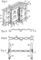
- the exchanger according to the invention consists of a stack of juxtaposed metal plates of substantially rectangular shape and there is shown in Figure 1, six of these plates 10, 11, 12, 13, 14 and 15 some of which have been cut transversely so as to highlight the particularities of assembly.
- the first pair, 10-11 is shown to its anterior edge while the other two pairs have been sectioned along different transverse vertical planes.
- the plates of the same pair define between them an interval designated by the reference A, and the pairs define between them intervals designated by the reference B.
- the intervals A are intended for the circulation of a first fluid and the intervals B are intended for the circulation of a second fluid, with the aim of ensuring a heat exchange between them through the plates.
- the intervals A and B are closed, at least at the top and bottom by the fact that each plate is connected at its periphery to the two adjacent plates, in a sealed manner.
- the plates of the same pair for example 14-15, are welded together by linear welds 16 and 17 in their upper and lower end zones.
- these welds can be produced, for example, by electrical welding with a thumbwheel, as will be explained below.
- the plates comprise wings 18, 19, 20, 21 connected to their upper and lower end zones, and folded substantially at right angles, which makes it possible to assemble the pairs of plates together.
- the pairs are assembled side by side, so that the wings 20, 21 of a plate (14) of a first pair (14-15) are arranged edge to edge relative to the wings ( 22, 23) of the plate 13 facing the neighboring pair (12-13) and the wings are welded to each other (20 and 22, 21 and 23) by a linear weld bead, by example by arc welding.
- the plates of the same pair (10-11) are also welded to each other along their anterior extreme zone 24, either by electrical welding with a thumbwheel, or by cord arc welding.
- Fluid inlet and outlet openings to the intervals A are provided in the form of interruptions in the upper linear welds 16 and lower 17.
- a single orifice 25 has been illustrated in FIG. 1, at the level of the upper weld 16, and in the vicinity of the anterior end zone 24.
- the other orifice, not shown, is arranged in the vicinity of the posterior end zone, optionally at the level of the upper weld 16 or the lower weld 17.
- the pairs of plates are devoid of wings at their anterior and posterior end zones, so that there remain free openings between the pairs of plates, which thus constitute the inlet and outlet orifices for the fluid circulating in intervals B.
- the plates have depressions 26 distributed substantially regularly over the surface of the plates and whose role is multiple.
- the plates are welded to each other by points at the bottom of the depressions, this preventing the spacing of the plates when, on the contrary, the fluid pressure prevailing in the intervals A exceeds that which prevails in the intervals B.
- these depressions create obstacles to the flow of the fluid in the intervals A and the turbulences which result from it improve the heat exchanges between this fluid and the plates.
- depressions can be arranged in regular rows as illustrated, or in staggered rows or according to any predetermined arrangement.
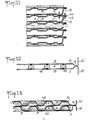
- the insulated plate 10 illustrated in Figure 2 was obtained in a conventional manner by stamping the depressions 26 and folding the wings square.
- This plate is then assembled to a second plate 11 by spot welding at the bottom of the depressions 26 ( Figure 3).
- Weld beads 16, 17 are then produced in the vicinity of the feet of the wings, by electrical welding using knobs 28, 29 (FIG. 4), it being noted that the plates initially spaced from one another ( Figure 3) are forced to move together under the pressure of the knobs. This is made possible by the small thickness of the plates and their small spacing and avoids a prior drilling operation.
- a first pair of plates (10-11) is then assembled to a second pair of plates (12-13) constituted in the above manner, by presenting the wings of both in edge-to-edge relationship and then by making a linear weld seam, for example by arc welding.
- the plates thus assembled form a monobloc assembly to which we associate inlet and outlet manifolds for the fluids circulating in the intervals A and B.
- a manifold 30 in the form of a rectangular pipe is welded to the perimeter of the front end of the exchanger plates.
- a similar manifold, not shown, is welded to the perimeter of the rear end of the exchanger plates.
- a semi-cylindrical manifold 32 is welded transversely to all of the plates, so as to cover all of the orifices 25 for the fluid flowing in the intervals A.
- the front edge (according to the arrangement of FIG. 8) of the collector 32 is welded to the upper face of the collector 30, and its rear edge is welded to a pseudo-planar and almost continuous surface, formed by the succession of the wings of the plates exchanger. These welds are preferably carried out with the addition of metal so as to provide the required seal.
- the front edge of the manifold 32 can also be welded to the wings of the exchanger plates, provided that the orifices 25 are formed somewhat behind the front edges 24 of the plates.
- a wedge 34 in the form of a wedge is introduced between two plates of a pair 10-11 so as to prevent the advance of the welding knobs 28 , 29, in the orifice area.
- support plates 36, 38 must be provided in the vicinity of the exchanger plates situated at the ends (FIG. 6). These support plates are juxtaposed, without attachment, to the exchanger plates so as to allow differential expansion and are joined to one another by tie rods 40, dimensioned and distributed to absorb the forces due to the pressure of the fluid circulating in the intervals B.
- the pairs are assembled by welding the wings of a plate directly to the edges of a plate devoid of wings of the neighboring pair.
- the plates carrying the wings are entirely flat and the plates devoid of wings carry the depressions 26.
- the plates devoid of wings carry the depressions 26.
- the plates When assembling in pairs, the plates are placed head to tail, then the pairs are assembled, as before, by welding the edge of the wings to the edge of the facing plates.
- the wings are extended by a flap 42, and the ends of plates devoid of wings comprising an extension 44.
- the flaps and the extensions are welded flat by electric welding with a seam.
- notches can be regularly distributed along the rear edge of the manifold, to receive these projections.
- the exchanger plates are completely flat and during assembly in pairs, metal spacers 46 are interposed between them which are spot welded to the two plates.
- the plates are of the corrugation type, the corrugations of one (48) having a different orientation from the corrugations (50) of the adjacent plate.
- the plates are joined in pairs by seam welding along their edge, as seen above. It is also possible to provide for joining or not joining the two plates by spot welds in the zones where the top of the corrugations of one is in contact with the bottom of the corrugations of the other as illustrated by the points P in the figure.
- the plates are assembled in pairs by linear welding without the addition of metal in two opposite end zones, and that at least one plate in each pair has a wing located in at least one of these extreme zones and in the vicinity of the linear weld, folded back to the square and connected in its free marginal zone to a plate opposite a neighboring pair, by linear weld.
Landscapes
- Engineering & Computer Science (AREA)
- Physics & Mathematics (AREA)
- Thermal Sciences (AREA)
- Mechanical Engineering (AREA)
- General Engineering & Computer Science (AREA)
- Heat-Exchange Devices With Radiators And Conduit Assemblies (AREA)
- Separation By Low-Temperature Treatments (AREA)
Claims (7)
Applications Claiming Priority (2)
| Application Number | Priority Date | Filing Date | Title |
|---|---|---|---|
| FR8419707A FR2575279B1 (fr) | 1984-12-21 | 1984-12-21 | Echangeur a plaques |
| FR8419707 | 1984-12-21 |
Publications (2)
| Publication Number | Publication Date |
|---|---|
| EP0186592A1 EP0186592A1 (de) | 1986-07-02 |
| EP0186592B1 true EP0186592B1 (de) | 1988-10-26 |
Family
ID=9310913
Family Applications (1)
| Application Number | Title | Priority Date | Filing Date |
|---|---|---|---|
| EP85402573A Expired EP0186592B1 (de) | 1984-12-21 | 1985-12-20 | Plattenwärmetauscher |
Country Status (5)
| Country | Link |
|---|---|
| US (1) | US4688631A (de) |
| EP (1) | EP0186592B1 (de) |
| JP (1) | JPH0692877B2 (de) |
| DE (1) | DE3565889D1 (de) |
| FR (1) | FR2575279B1 (de) |
Cited By (7)
| Publication number | Priority date | Publication date | Assignee | Title |
|---|---|---|---|---|
| US6289977B1 (en) | 1996-10-11 | 2001-09-18 | Ziepack | Heat exchanger, and heat exchanging beam, and related welding methods and production |
| EP3306253A1 (de) | 2016-10-07 | 2018-04-11 | Airec Ab | Wärmetauscherplatte und wärmetauscher |
| EP3351886A1 (de) | 2017-01-19 | 2018-07-25 | Airec Ab | Wärmetauscherplatte und wärmetauscher |
| EP3447429A1 (de) | 2017-08-22 | 2019-02-27 | Airec AB | Wärmetauscherplatte und wärmetauscher |
| EP3447427A1 (de) | 2017-08-22 | 2019-02-27 | Airec AB | Wärmetauscher |
| EP3447428A1 (de) | 2017-08-22 | 2019-02-27 | Airec AB | Wärmetauscherplatte und wärmetauscher |
| EP3671096A1 (de) | 2018-12-21 | 2020-06-24 | InnoHeat Sweden AB | Wärmetauscherplatte und wärmetauscher |
Families Citing this family (77)
| Publication number | Priority date | Publication date | Assignee | Title |
|---|---|---|---|---|
| DE3509895A1 (de) * | 1985-03-19 | 1986-09-25 | ZUGLA AG, Glarus | Plattenfoermiges heizelement, insbesondere fuer fussbodenheizungen |
| US4807342A (en) * | 1985-05-13 | 1989-02-28 | The Laitram Corporation | Method for making an improved heat exchanger |
| KR940010978B1 (ko) * | 1988-08-12 | 1994-11-21 | 갈소니꾸 가부시끼가이샤 | 멀티플로우형의 열교환기 |
| JPH03504761A (ja) * | 1989-02-03 | 1991-10-17 | ザポロジスキイ アフトモビルニイ ザボト “コミュナル”(プロイズボドストベンノエ オビエディネニエ “アフトザズ”) | プレート形熱交換器 |
| US4860421A (en) * | 1989-02-23 | 1989-08-29 | General Motors Corporation | Method for assembling plate type heat exchangers |
| EP0439046B1 (de) | 1990-01-22 | 1993-09-22 | Atd Corporation | Kissenartig geformtes Gebilde mit Wärmeleitzonen und thermischen Isolierzonen und verformbares Laminat |
| US5111577A (en) * | 1990-01-22 | 1992-05-12 | Atd Corporation | Pad including heat sink and thermal insulation areas |
| DE9002440U1 (de) * | 1990-03-02 | 1990-05-03 | Sueddeutsche Kuehlerfabrik Julius Fr. Behr Gmbh & Co Kg, 7000 Stuttgart | Wärmetauscher, insbesonder Ölkühler für Kraftfahrzeuge |
| DE4009556C2 (de) * | 1990-03-24 | 1994-07-07 | Schmid Christoph | Wärmeübertrager |
| US5271151A (en) * | 1990-04-23 | 1993-12-21 | Wallis Bernard J | Method of making a high pressure condenser |
| FR2685462B1 (fr) * | 1991-12-23 | 1999-02-05 | Andre Peze | Echangeur de chaleur a plaques soudees et procede de fabrication de modules de plaques permettant l'obtention de tels echangeurs. |
| IT226255Z2 (it) * | 1992-02-18 | 1997-06-02 | Miralfin Srl | Struttura di radiatore particolarmente per il riscaldamento di locali |
| FR2690503B1 (fr) * | 1992-04-23 | 1994-06-03 | Commissariat Energie Atomique | Evaporateur a plaques a hautes performances thermiques fonctionnant en regime d'ebullition nucleee. |
| FR2690986B1 (fr) * | 1992-05-05 | 1998-06-12 | Fernandez Jean Noel | Echangeurs a plaques soudees a circuit autoresistant a la pression et nouvelles plaques permettant la realisation de tels echangeurs. |
| FR2691528B1 (fr) * | 1992-05-22 | 1997-05-23 | Packinox Sa | Faisceau de plaques pour echangeur thermique et procede d'assemblage d'un tel faisceau de plaques. |
| US5228515A (en) * | 1992-07-31 | 1993-07-20 | Tran Hai H | Modular, compact heat exchanger |
| DE4227122C2 (de) * | 1992-08-17 | 2001-12-20 | Deutz Ag | Luft-Flüssigkeits-Wärmetauscher |
| US5320168A (en) * | 1993-04-23 | 1994-06-14 | Haight Ehrick K | Heat exchange system for processing solid particulates |
| US5469914A (en) * | 1993-06-14 | 1995-11-28 | Tranter, Inc. | All-welded plate heat exchanger |
| DE4422283C1 (de) * | 1994-06-25 | 1995-09-28 | Balcke Duerr Ag | Verfahren zum Verschweißen von kammartigen Abdichtleisten an Plattenwärmetauschern |
| DE19540683A1 (de) * | 1995-11-01 | 1997-05-07 | Behr Gmbh & Co | Wärmeüberträger zum Kühlen von Abgas |
| US5823247A (en) * | 1996-08-16 | 1998-10-20 | Weibler; Walter W. | Heat exchanger and method |
| EP0933608B1 (de) | 1996-10-17 | 2003-04-02 | Honda Giken Kogyo Kabushiki Kaisha | Wärmetauscher |
| IL124723A (en) * | 1998-06-02 | 2004-01-04 | Pessach Seidel | Method of forming a heat exchanger stack |
| SE512240C2 (sv) * | 1998-06-24 | 2000-02-14 | Alfa Laval Ab | Sätt att sammanfoga åtminstone fyra värmeöverföringsplattor till ett plattpaket jämte plattpaket |
| FR2780493B1 (fr) | 1998-06-26 | 2000-08-11 | Sarl Thermi Consult | Echangeur de chaleur a plaques assurant la fonction de condenseur |
| DE19833338A1 (de) * | 1998-07-24 | 2000-01-27 | Modine Mfg Co | Wärmetauscher, insbesondere Abgaswärmetauscher |
| FR2781562B1 (fr) | 1998-07-24 | 2000-09-22 | Sarl Thermi Consult | Echangeur de chaleur a plaques assurant la fonction de condenseur |
| DE19846518B4 (de) * | 1998-10-09 | 2007-09-20 | Modine Manufacturing Co., Racine | Wärmetauscher, insbesondere für Gase und Flüssigkeiten |
| AU5167000A (en) | 1999-05-27 | 2000-12-18 | Thomas & Betts International, Inc. | Compact high-efficient air heater |
| SE514714C2 (sv) * | 1999-08-27 | 2001-04-09 | Alfa Laval Ab | Lödd plattvärmeväxlare med dubbelväggiga plattor utan inre anliggning mittför lödförbindningarna |
| DE10082698D2 (de) * | 1999-09-03 | 2002-01-24 | Ryll Heizungs Gmbh | Wärmetauscher |
| GB2361993A (en) * | 2000-03-10 | 2001-11-07 | Smiths Group Plc | Ventilation System with Heat Recovery Unit |
| US6438936B1 (en) | 2000-05-16 | 2002-08-27 | Elliott Energy Systems, Inc. | Recuperator for use with turbine/turbo-alternator |
| US6615471B2 (en) | 2001-02-12 | 2003-09-09 | Solar Turbines Inc | Method of locating the blade holders in a fin folding machine |
| US6516874B2 (en) | 2001-06-29 | 2003-02-11 | Delaware Capital Formation, Inc. | All welded plate heat exchanger |
| JP2003021489A (ja) * | 2001-07-06 | 2003-01-24 | Toyo Radiator Co Ltd | 熱交換器の接合構造 |
| US7077190B2 (en) * | 2001-07-10 | 2006-07-18 | Denso Corporation | Exhaust gas heat exchanger |
| JP2003194490A (ja) * | 2001-12-27 | 2003-07-09 | Xenesys Inc | 熱交換ユニット |
| JP3917870B2 (ja) * | 2002-01-30 | 2007-05-23 | 株式会社電元社製作所 | シーム溶接装置 |
| EP1435504A1 (de) * | 2003-01-02 | 2004-07-07 | Hubert Antoine | Prismatischer Wärmteauscher |
| US6904961B2 (en) * | 2003-01-07 | 2005-06-14 | Honeywell International, Inc. | Prime surface gas cooler for high temperature and method for manufacture |
| DE10324089A1 (de) * | 2003-02-13 | 2004-09-02 | Loher Gmbh | Rekuperativer Plattenwärmetauscher |
| CA2420273A1 (en) * | 2003-02-27 | 2004-08-27 | Peter Zurawel | Heat exchanger plates and manufacturing method |
| US7147050B2 (en) * | 2003-10-28 | 2006-12-12 | Capstone Turbine Corporation | Recuperator construction for a gas turbine engine |
| DE102004018197A1 (de) * | 2004-04-15 | 2005-11-03 | Modine Manufacturing Co., Racine | Abgaswärmetauscher |
| ES2285337T5 (es) * | 2004-11-10 | 2010-10-04 | Modine Manufacturing Company | Intercambiador de calor con perfil abierto como alojamiento. |
| EP1705445A1 (de) * | 2005-03-04 | 2006-09-27 | Methanol Casale S.A. | Verfahren zum Herstellen von Plattenwärmetauschern und Gerät dafür. |
| JP2006317029A (ja) * | 2005-05-10 | 2006-11-24 | Xenesys Inc | 熱交換ユニット |
| JP5145718B2 (ja) * | 2006-02-03 | 2013-02-20 | 株式会社デンソー | 熱交換器 |
| FR2901016B1 (fr) * | 2006-05-12 | 2008-07-18 | Kapp France Sa | Echangeur de chaleur a plaques d'echange soudees |
| KR101250771B1 (ko) * | 2006-09-21 | 2013-04-04 | 한라공조주식회사 | 열교환기 |
| JP4775287B2 (ja) * | 2006-10-18 | 2011-09-21 | 株式会社デンソー | 熱交換器 |
| JP2009063223A (ja) * | 2007-09-06 | 2009-03-26 | Denso Corp | 熱交換器 |
| DE102007056717B3 (de) * | 2007-11-26 | 2009-02-12 | Gesmex Gmbh | Verfahren zum Verbinden von mindestens zwei Wärmetauscherplatten |
| GB2460399A (en) * | 2008-05-21 | 2009-12-02 | Eco Intellect Ltd | Heat recovery system |
| US8540012B2 (en) * | 2008-06-13 | 2013-09-24 | Lockheed Martin Corporation | Heat exchanger |
| US20100181054A1 (en) * | 2009-01-21 | 2010-07-22 | Lockheed Martin Corporation | Plate-Frame Graphite-Foam Heat Exchanger |
| EP2224197A3 (de) * | 2009-02-25 | 2013-01-09 | Ying Lin Cai | Wärmetauscher für Dusche |
| US9541331B2 (en) | 2009-07-16 | 2017-01-10 | Lockheed Martin Corporation | Helical tube bundle arrangements for heat exchangers |
| CN102812320B (zh) | 2009-07-17 | 2016-09-07 | 洛克希德马丁公司 | 热交换器及其制作方法 |
| US9777971B2 (en) * | 2009-10-06 | 2017-10-03 | Lockheed Martin Corporation | Modular heat exchanger |
| US20110127022A1 (en) * | 2009-12-01 | 2011-06-02 | Lockheed Martin Corporation | Heat Exchanger Comprising Wave-shaped Fins |
| NL2004565C2 (en) * | 2010-04-16 | 2011-10-18 | Mircea Dinulescu | Plate type heat exchanger having outer heat exchanger plates with improved connections to end panels. |
| US9388798B2 (en) | 2010-10-01 | 2016-07-12 | Lockheed Martin Corporation | Modular heat-exchange apparatus |
| US9670911B2 (en) | 2010-10-01 | 2017-06-06 | Lockheed Martin Corporation | Manifolding arrangement for a modular heat-exchange apparatus |
| FR2990148B1 (fr) * | 2012-05-03 | 2014-11-14 | Ferri Jean Noel Fernandez | Echangeur a plaques soudees matelassees et nouvelles plaques permettant leur realisation |
| NL2012066C2 (nl) * | 2014-01-09 | 2015-07-13 | Intergas Heating Assets B V | Warmtewisselaar, werkwijze voor het vormen daarvan en gebruik daarvan. |
| WO2017174553A1 (en) | 2016-04-08 | 2017-10-12 | Ineos Europe Ag | Polymerisation unit and polymerisation process |
| USD889420S1 (en) * | 2018-01-05 | 2020-07-07 | Baltimore Aircoil Company, Inc. | Heat exchanger cassette |
| US10677538B2 (en) | 2018-01-05 | 2020-06-09 | Baltimore Aircoil Company | Indirect heat exchanger |
| CN111819403B (zh) * | 2018-03-07 | 2022-07-08 | 达纳加拿大公司 | 带有一体式电加热元件和多个流体流动通路的热交换器 |
| FR3079606B1 (fr) * | 2018-03-30 | 2020-07-17 | Groupe H Labbe | Procede d'assemblage d'un echangeur thermique |
| US11255534B2 (en) * | 2018-10-03 | 2022-02-22 | Coretronic Corporation | Thermal module and projector |
| CN111928705B (zh) * | 2019-05-13 | 2022-03-25 | 亚浩电子五金塑胶(惠州)有限公司 | 具有重力型回路热管的散热装置 |
| DE202019103895U1 (de) * | 2019-07-15 | 2020-10-16 | Reinz-Dichtungs-Gmbh | Plattenartiger Fluidbehälter |
| FR3119447B1 (fr) | 2021-01-29 | 2023-04-14 | Groupe H Labbe | échangeur de chaleur a plaques |
Family Cites Families (16)
| Publication number | Priority date | Publication date | Assignee | Title |
|---|---|---|---|---|
| US2169993A (en) * | 1937-04-12 | 1939-08-22 | Noblitt Sparks Ind Inc | Radiator |
| FR998449A (fr) * | 1945-10-03 | 1952-01-18 | Mode de construction pour échangeur de chaleur | |
| US2586118A (en) * | 1946-11-27 | 1952-02-19 | Affiliated Gas Equipment Inc | Furnace heat exchanger |
| GB823951A (en) * | 1956-03-27 | 1959-11-18 | Parsons C A & Co Ltd | Improvements in and relating to heat exchangers |
| GB822421A (en) * | 1957-09-07 | 1959-10-28 | W J Frazer & Co Ltd | Heat exchanger |
| US3228464A (en) * | 1963-08-09 | 1966-01-11 | Avco Corp | Corrugated plate counter flow heat exchanger |
| FR1389144A (fr) * | 1964-03-02 | 1965-02-12 | échangeur de chaleur | |
| DE1455760B2 (de) * | 1965-12-23 | 1976-04-22 | Kühlvorrichtung für ein gepanzertes Fahrzeug Dr.Ing.h.c. F. Porsche AG, 7000 Stuttgart | Kuehlvorrichtung fuer ein gepanzertes fahrzeug |
| SE318847B (de) * | 1966-08-22 | 1969-12-22 | Rosenblads Patenter Ab | |
| GB1253307A (en) * | 1969-03-20 | 1971-11-10 | Rootes Motors Ltd | Improvements in or relating to methods of making heat exchangers |
| SE352724B (de) * | 1969-11-10 | 1973-01-08 | Thermovatic Jenssen S | |
| CH524800A (de) * | 1971-11-26 | 1972-06-30 | Runtal Holding Co Sa | Vorrichtung zur Rollnahtdichtschweissung der Seitenränder von Platten-Radiatoren |
| JPS5111724Y2 (de) * | 1972-07-27 | 1976-03-30 | ||
| JPS53137460A (en) * | 1977-05-07 | 1978-11-30 | Howa Mach Ltd | Parting plate for heat exchanger |
| JPS5877218A (ja) * | 1981-10-31 | 1983-05-10 | Toshiba Corp | 油入電気機器用タンクの製造方法 |
| JPS58112874U (ja) * | 1982-01-26 | 1983-08-02 | 三菱電機株式会社 | 熱交換装置 |
-
1984
- 1984-12-21 FR FR8419707A patent/FR2575279B1/fr not_active Expired
-
1985
- 1985-12-20 US US06/811,280 patent/US4688631A/en not_active Expired - Lifetime
- 1985-12-20 JP JP60287620A patent/JPH0692877B2/ja not_active Expired - Lifetime
- 1985-12-20 DE DE8585402573T patent/DE3565889D1/de not_active Expired
- 1985-12-20 EP EP85402573A patent/EP0186592B1/de not_active Expired
Cited By (16)
| Publication number | Priority date | Publication date | Assignee | Title |
|---|---|---|---|---|
| US6289977B1 (en) | 1996-10-11 | 2001-09-18 | Ziepack | Heat exchanger, and heat exchanging beam, and related welding methods and production |
| EP3306253A1 (de) | 2016-10-07 | 2018-04-11 | Airec Ab | Wärmetauscherplatte und wärmetauscher |
| US12044486B2 (en) | 2016-10-07 | 2024-07-23 | Alfa Laval Corporate Ab | Heat exchanging plate and heat exchanger |
| US10989482B2 (en) | 2017-01-19 | 2021-04-27 | Alfa Laval Corporate Ab | Heat exchanging plate and heat exchanger |
| EP3351886A1 (de) | 2017-01-19 | 2018-07-25 | Airec Ab | Wärmetauscherplatte und wärmetauscher |
| WO2018133954A1 (en) | 2017-01-19 | 2018-07-26 | Airec Ab | Heat exchanging plate and heat exchanger |
| EP3447429A1 (de) | 2017-08-22 | 2019-02-27 | Airec AB | Wärmetauscherplatte und wärmetauscher |
| WO2019038282A1 (en) | 2017-08-22 | 2019-02-28 | Airec Ab | HEAT EXCHANGER PLATE AND HEAT EXCHANGER |
| WO2019038281A1 (en) | 2017-08-22 | 2019-02-28 | Airec Ab | HEAT EXCHANGER PLATE AND HEAT EXCHANGER |
| WO2019038279A1 (en) | 2017-08-22 | 2019-02-28 | Airec Ab | HEAT EXCHANGER |
| EP3447428A1 (de) | 2017-08-22 | 2019-02-27 | Airec AB | Wärmetauscherplatte und wärmetauscher |
| US11105561B2 (en) | 2017-08-22 | 2021-08-31 | Innoheat Sweden Ab | Heat exchanger plate and heat exchanger |
| US11105560B2 (en) | 2017-08-22 | 2021-08-31 | Innoheat Sweden Ab | Heat exchanger |
| EP3447427A1 (de) | 2017-08-22 | 2019-02-27 | Airec AB | Wärmetauscher |
| EP3671096A1 (de) | 2018-12-21 | 2020-06-24 | InnoHeat Sweden AB | Wärmetauscherplatte und wärmetauscher |
| WO2020127081A1 (en) | 2018-12-21 | 2020-06-25 | Innoheat Sweden Ab | Heat exchanger plate and heat exchanger |
Also Published As
| Publication number | Publication date |
|---|---|
| JPH0692877B2 (ja) | 1994-11-16 |
| US4688631A (en) | 1987-08-25 |
| EP0186592A1 (de) | 1986-07-02 |
| DE3565889D1 (en) | 1988-12-01 |
| FR2575279A1 (fr) | 1986-06-27 |
| FR2575279B1 (fr) | 1989-07-07 |
| JPS61153500A (ja) | 1986-07-12 |
Similar Documents
| Publication | Publication Date | Title |
|---|---|---|
| EP0186592A1 (de) | Plattenwärmetauscher | |
| EP0165179B1 (de) | Plattenwärmetauscher und Platte zu dessen Herstellung | |
| EP2376860B1 (de) | Wärmetauscher mit geschweissten platten | |
| EP1192402B1 (de) | Wärmetauscher mit mehrkanalrohren | |
| EP0447528B1 (de) | Fahrzeugkondensator | |
| EP0811820A1 (de) | Flachrohr mit einem in der Mitte befindlichen Distanzhalter für Wärmetauscher | |
| EP0571263A1 (de) | Plattenstapel für Wärmetauscher und Verfahren zu dessen Zusammenbau | |
| EP1426722B1 (de) | Wärmetauscherplatte und Plattenwärmetauscher | |
| EP2105693B1 (de) | Hochleistungwärmetauscher | |
| EP3234488B1 (de) | Wärmeaustauschplatte mit mikrokanälen und wärmetauscher mit mindestens einer solchen platte | |
| EP3447432B1 (de) | Wärmetauscherplatte mit mikrokanälen, die ein montagelement für den rand der platte umfasst | |
| WO2020065224A1 (fr) | Plaque constitutive d'un échangeur de chaleur et échangeur de chaleur comprenant au moins une telle plaque | |
| WO2017032567A1 (fr) | Échangeur de chaleur | |
| FR2837917A1 (fr) | Echangeur de chaleur, notamment pour un vehicule automobile, constitue d'elements tubulaires empiles | |
| EP0099835A2 (de) | Wärmetauscher mit Modulstruktur | |
| WO2005064258A1 (fr) | Module pour l'echange de chaleur entre fluides en circulation | |
| FR2866699A1 (fr) | Echangeur thermique a plaques nervurees soudees | |
| FR2728668A1 (fr) | Echangeur de chaleur a empilement d'ailettes | |
| EP0851998A1 (de) | Plattenstapel für einen wärmetauscher und wärmetauscher mit einem solchen plattenstapel | |
| WO2024251686A1 (fr) | Elément interne d'échangeur de chaleur | |
| FR2716960A1 (fr) | Faisceau de plaques pour un échangeur thermique. | |
| FR2929387A1 (fr) | Echangeur de chaleur a resistance a la pression amelioree | |
| EP1623177A2 (de) | Wärmetauscher, insbesondere für kraftfahrzeuge |
Legal Events
| Date | Code | Title | Description |
|---|---|---|---|
| PUAI | Public reference made under article 153(3) epc to a published international application that has entered the european phase |
Free format text: ORIGINAL CODE: 0009012 |
|
| AK | Designated contracting states |
Kind code of ref document: A1 Designated state(s): CH DE GB IT LI SE |
|
| 17P | Request for examination filed |
Effective date: 19861031 |
|
| 17Q | First examination report despatched |
Effective date: 19870227 |
|
| D17Q | First examination report despatched (deleted) | ||
| ITF | It: translation for a ep patent filed | ||
| GRAA | (expected) grant |
Free format text: ORIGINAL CODE: 0009210 |
|
| 111L | Licence recorded |
Free format text: 0100 BUSS AG |
|
| AK | Designated contracting states |
Kind code of ref document: B1 Designated state(s): CH DE GB IT LI SE |
|
| R11L | Licence recorded (corrected) |
Free format text: 0100 BUSS AG |
|
| R11L | Licence recorded (corrected) |
Free format text: 0100 BUSS AG |
|
| REF | Corresponds to: |
Ref document number: 3565889 Country of ref document: DE Date of ref document: 19881201 |
|
| GBT | Gb: translation of ep patent filed (gb section 77(6)(a)/1977) | ||
| REG | Reference to a national code |
Ref country code: CH Ref legal event code: PLI Owner name: BUSS AG |
|
| PLBE | No opposition filed within time limit |
Free format text: ORIGINAL CODE: 0009261 |
|
| STAA | Information on the status of an ep patent application or granted ep patent |
Free format text: STATUS: NO OPPOSITION FILED WITHIN TIME LIMIT |
|
| 26N | No opposition filed | ||
| REG | Reference to a national code |
Ref country code: CH Ref legal event code: PLIA Free format text: BUSS AG |
|
| ITTA | It: last paid annual fee | ||
| EAL | Se: european patent in force in sweden |
Ref document number: 85402573.1 |
|
| REG | Reference to a national code |
Ref country code: CH Ref legal event code: PUE Owner name: BARRIQUAND TRANSFER- BARRIQUAND ECHANGEURS |
|
| REG | Reference to a national code |
Ref country code: GB Ref legal event code: IF02 |
|
| PGFP | Annual fee paid to national office [announced via postgrant information from national office to epo] |
Ref country code: SE Payment date: 20041119 Year of fee payment: 20 |
|
| PGFP | Annual fee paid to national office [announced via postgrant information from national office to epo] |
Ref country code: DE Payment date: 20041206 Year of fee payment: 20 |
|
| PGFP | Annual fee paid to national office [announced via postgrant information from national office to epo] |
Ref country code: GB Payment date: 20041207 Year of fee payment: 20 |
|
| PGFP | Annual fee paid to national office [announced via postgrant information from national office to epo] |
Ref country code: CH Payment date: 20041210 Year of fee payment: 20 |
|
| PG25 | Lapsed in a contracting state [announced via postgrant information from national office to epo] |
Ref country code: GB Free format text: LAPSE BECAUSE OF EXPIRATION OF PROTECTION Effective date: 20051219 |
|
| REG | Reference to a national code |
Ref country code: GB Ref legal event code: PE20 |
|
| REG | Reference to a national code |
Ref country code: CH Ref legal event code: PL |
|
| EUG | Se: european patent has lapsed |