EP2105693B1 - Hochleistungwärmetauscher - Google Patents
Hochleistungwärmetauscher Download PDFInfo
- Publication number
- EP2105693B1 EP2105693B1 EP09155369.3A EP09155369A EP2105693B1 EP 2105693 B1 EP2105693 B1 EP 2105693B1 EP 09155369 A EP09155369 A EP 09155369A EP 2105693 B1 EP2105693 B1 EP 2105693B1
- Authority
- EP
- European Patent Office
- Prior art keywords
- exchanger according
- elementary
- fluid
- path
- space
- Prior art date
- Legal status (The legal status is an assumption and is not a legal conclusion. Google has not performed a legal analysis and makes no representation as to the accuracy of the status listed.)
- Active
Links
Images

Classifications
-
- F—MECHANICAL ENGINEERING; LIGHTING; HEATING; WEAPONS; BLASTING
- F28—HEAT EXCHANGE IN GENERAL
- F28D—HEAT-EXCHANGE APPARATUS, NOT PROVIDED FOR IN ANOTHER SUBCLASS, IN WHICH THE HEAT-EXCHANGE MEDIA DO NOT COME INTO DIRECT CONTACT
- F28D1/00—Heat-exchange apparatus having stationary conduit assemblies for one heat-exchange medium only, the media being in contact with different sides of the conduit wall, in which the other heat-exchange medium is a large body of fluid, e.g. domestic or motor car radiators
- F28D1/02—Heat-exchange apparatus having stationary conduit assemblies for one heat-exchange medium only, the media being in contact with different sides of the conduit wall, in which the other heat-exchange medium is a large body of fluid, e.g. domestic or motor car radiators with heat-exchange conduits immersed in the body of fluid
- F28D1/03—Heat-exchange apparatus having stationary conduit assemblies for one heat-exchange medium only, the media being in contact with different sides of the conduit wall, in which the other heat-exchange medium is a large body of fluid, e.g. domestic or motor car radiators with heat-exchange conduits immersed in the body of fluid with plate-like or laminated conduits
- F28D1/0308—Heat-exchange apparatus having stationary conduit assemblies for one heat-exchange medium only, the media being in contact with different sides of the conduit wall, in which the other heat-exchange medium is a large body of fluid, e.g. domestic or motor car radiators with heat-exchange conduits immersed in the body of fluid with plate-like or laminated conduits the conduits being formed by paired plates touching each other
- F28D1/0325—Heat-exchange apparatus having stationary conduit assemblies for one heat-exchange medium only, the media being in contact with different sides of the conduit wall, in which the other heat-exchange medium is a large body of fluid, e.g. domestic or motor car radiators with heat-exchange conduits immersed in the body of fluid with plate-like or laminated conduits the conduits being formed by paired plates touching each other the plates having lateral openings therein for circulation of the heat-exchange medium from one conduit to another
- F28D1/0333—Heat-exchange apparatus having stationary conduit assemblies for one heat-exchange medium only, the media being in contact with different sides of the conduit wall, in which the other heat-exchange medium is a large body of fluid, e.g. domestic or motor car radiators with heat-exchange conduits immersed in the body of fluid with plate-like or laminated conduits the conduits being formed by paired plates touching each other the plates having lateral openings therein for circulation of the heat-exchange medium from one conduit to another the plates having integrated connecting members
- F28D1/0341—Heat-exchange apparatus having stationary conduit assemblies for one heat-exchange medium only, the media being in contact with different sides of the conduit wall, in which the other heat-exchange medium is a large body of fluid, e.g. domestic or motor car radiators with heat-exchange conduits immersed in the body of fluid with plate-like or laminated conduits the conduits being formed by paired plates touching each other the plates having lateral openings therein for circulation of the heat-exchange medium from one conduit to another the plates having integrated connecting members with U-flow or serpentine-flow inside the conduits
-
- F—MECHANICAL ENGINEERING; LIGHTING; HEATING; WEAPONS; BLASTING
- F28—HEAT EXCHANGE IN GENERAL
- F28D—HEAT-EXCHANGE APPARATUS, NOT PROVIDED FOR IN ANOTHER SUBCLASS, IN WHICH THE HEAT-EXCHANGE MEDIA DO NOT COME INTO DIRECT CONTACT
- F28D21/00—Heat-exchange apparatus not covered by any of the groups F28D1/00 - F28D20/00
- F28D2021/0019—Other heat exchangers for particular applications; Heat exchange systems not otherwise provided for
- F28D2021/008—Other heat exchangers for particular applications; Heat exchange systems not otherwise provided for for vehicles
- F28D2021/0085—Evaporators
Definitions
- the invention relates to the field of heat exchangers between two fluids, in particular for cooling a cooling liquid with air.
- heat exchangers are used in the field of air conditioning, for example motor vehicles.
- the invention relates to a heat exchanger according to the preamble of claim 1.
- Such an exchanger is known, for example, from the document EP 1 058 070 A2 .
- a heat exchanger including an evaporator for a vehicle air conditioning loop, defines a combined path for a first fluid formed of a plurality of first elementary paths and a combined path for a second fluid formed of a plurality of second elementary paths. .
- the first and second elementary paths are arranged alternately in a first direction so that each elementary path for one of the fluids is in thermal contact with at least one adjacent elementary path for the other fluid.
- the first fluid is a coolant or a heat transfer fluid and the second fluid is air.
- Each first elementary path has a U-shaped configuration whose two branches extend in a second direction and are offset relative to each other in a third direction.
- the first, second and third directions are substantially perpendicular to each other.
- each first path is made by means of tube made by folding, extrusion, by joining plates together or any other method of obtaining a heat exchanger circuit element.
- Each first path communicates with collecting spaces to provide a combined path extending from an inlet manifold space to an outlet manifold space of the heat exchanger.
- Each second elementary path extending in the third direction of an input face to an exit face of the exchanger.
- Each second path is generally made by a heat exchange spacer formed in a metal strip having louvers to promote heat exchange between the first fluid and the second fluid.
- At least one transition passage is formed between two collector spaces respectively belonging to two rows, so that, in the first elementary paths communicating directly with these two collector spaces, the fluid flows from one branch to the other in the same way. meaning in relation to the third direction.
- the fluid flows from one branch to the other in the same direction relative to the direction of flow of air, in first elementary paths directly communicating with these two collecting spaces.
- Such a heat exchanger is in particular known from the French patent application FR 2,825,791 which describes an evaporator for an air conditioning loop of a motor vehicle.
- the invention improves the situation.
- the invention is defined as a heat exchanger according to the subject of claim 1.
- the wall thickness of the elementary path is between 0.24 and 0.28 mm.
- the heat exchange is particularly effective between the first and second fluids.
- the tubes are coupled to at least one heat exchange spacer height in the first direction less than 5 mm, preferably between 3 mm and 4.5 mm.
- the wall thickness of the tubes is less than or equal to 0.27 mm and the tubes have an internal height in the first direction is less than 1.5 mm, preferably between 1 mm and 1.3 mm.
- the first elementary paths are arranged in two layers in a third direction.
- the first, second and third directions are substantially perpendicular to each other.
- Each second elementary path of the second fluid extends in the third direction of an entry face to an exit face of the heat exchanger.
- the first elementary paths of a web are offset relative to each other in a first direction.
- the entry face of the second fluid is close to the second sheet of first elementary paths.
- the exit face of the second fluid is close to the first sheet of first elementary paths.
- Each first elementary path opens into collecting spaces.
- the collecting spaces are connected to first elementary paths of a web.
- the collector spaces of the same ply communicate in pairs so as to establish a combined path extending from an inlet collector space to an outlet collector space located at opposite plies of the exchanger in the third direction.
- at least one transition space is provided between two collector spaces respectively belonging to the two plies, so that the first fluid flows from the first ply to the second ply.
- the surface of the transition space is between 60% and 80% of the area of the first elementary paths of the third pass, preferably between 65% and 75%.
- the transition space is formed by a bulge of the sheets having a radius of between 8.5 mm and 10 mm.
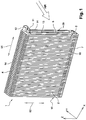
- the heat exchanger 1 comprises a stack of tubes 2 and heat exchange tabs 44 and 45.
- Each tube 2 is formed of two plates 3 and 4 respectively formed from a metal strip shaped cups.
- the plates 3 and 4 are identical to each other and have their concavities turned towards each other, respectively upwards and downwards of the figure 3 , that is, according to the direction xx.
- Each plate 3 and 4 has a peripheral edge 5.
- the peripheral edges 5 of the two plates 3 and 4 forming a tube 2 are mutually assembled in a fluid-tight manner, for example by brazing to define the internal volume of the tube 2.
- the tube 2 forms two first elementary paths 13 and 14 for a first fluid, in particular a refrigerant circulating in an air conditioning loop of a vehicle automobile or a coolant circulating in a cooling circuit of a combustion engine of a motor vehicle.
- Each tube 2 has two end regions 6 and 7, located respectively downwards and upwards of the figure 1 , that is to say in the zz direction, defined by deep stampings formed in the plates 3 and 4.
- the end regions 6 and 7 occupy a minor fraction of the height of the exchanger 1 at the upper and lower parts. bottom of it, the rest of the height being occupied by a body region of smaller thickness, as detailed in sectional view on the figure 3 .
- the interior volumes of the end regions 6 and 7 of each tube are separated from each other by a sealed junction zone 8 extending from the upper end region 6 to the lower end region. 7.
- the sealed junction zone 8 is arranged between the fluid passages defining the elementary paths 13 and 14 at the half-width of the tube 2 in the yy direction, this junction zone 8 extending downwards in the zz direction to adjacent to the lower end 7 of the tube 2.
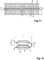
- a plate 3 and a neighboring plate 4 belonging to two different tubes 2 are in mutual support by their bottoms 9 in the end regions 6 and 7, also illustrated in FIG. figure 10 , and separated from each other in the body region, by an interval packed with heat exchange tab 44 and 45 illustrated on the Figures 11 and 12 .
- the heat exchange tabs 44 and 45 define a second elementary path for the air to be cooled, parallel to the plan of the figure 4 , that is to say in the direction yy, and in the direction of the arrow "AIR" illustrated on the Figures 1 and 2 .
- the tubes 2 are thus coupled to at least one thermal exchange spacer 44 and / or 45.
- Funds 9 in mutual contact are soldered together. At least a portion of the funds 9 are traversed by openings 10 communicating with each other the corresponding interior volumes. Watertight partitions 16 are arranged in certain openings 10 to close them to define a particular circuit, said multi pass.
- the heat exchanger 1 comprises a fluid inlet insert 11 and a fluid outlet insert 12 disposed on an outer face of the end region 6 of a tube 2 arranged at one end of the exchanger 1, that is to say at the end in direction xx.
- the inserts 11 and 12 may have different diameters.
- the inserts 11 and 12 define an inlet or outlet tubing projecting from a short side of the heat exchanger 1.
- the exemplary embodiment described by way of example in figure 1 has the fluid inlet 11 and fluid outlet inserts 12 arranged on the same side of the heat exchanger 1.
- the present invention also covers the other arrangements in which the inserts are arranged at the two opposite ends of a same end zone or disposed at both ends of two end zones disposed on the same side of the exchanger or at two opposite ends of two end zones. These arrangements are dependent on the bulkheads 16 arranged in certain openings 10.
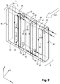
- FIG 2 showing a diagram of an example of circulation of fluids in the heat exchanger 1 according to the present invention.
- the refrigerant entering the heat exchanger 1 by the fluid inlet insert 11 is distributed through a collector space 17, between the inner volumes of the regions 6 between one end of the heat exchanger 1, located to the right of the figure 1 in the direction xx, and a partition 16 formed by the bottoms of two plates 3 and 4 not provided with openings 10.
- From the collector space 17, the fluid travels in parallel the elementary paths 13 delimited by the tubes 2 which define it.
- the elementary paths 13 near the inlet face of the fluid 15 form a first pass 31 and open into a second collecting space 18 formed by the interior volumes of the regions 7 of the same tubes 2 which form the collecting space 17.
- the collecting space 18 communicates through an opening 10 with a third collecting space 19, which in turn is connected to a fourth collecting space 20, separated from the collecting space 17 by the partition 16, by means of elementary paths forming a second pass 32.
- the collecting space 20 communicates through an opening 10 with a fifth collecting space 21, which in turn is connected to a sixth collecting space 22, separated from the collecting space 19 by a partition 16, the communication between the fifth and sixth collecting spaces being made via elementary paths forming a third pass 33.
- the refrigerant entering through the insert 11 thus passes through all the branches located on the side of the inlet face of the fluid 15, then, between the sixth collecting space 22 and a seventh collecting space 23, flows in the opposite direction to the flow of air through passages 41, which are illustrated on the Figures 6 and 7 and will be detailed in relation to these figures.
- the refrigerant then flows from the seventh collecting space 23 to the eighth collecting space 24 in passing through the elementary paths 14 forming the fourth pass 34, then moves in the first direction 51 or direction xx, communicating through an opening 10 to the ninth collecting space 25.
- the refrigerant circulates in the fifth pass 35 and joined by the intermediate elementary paths 14 a tenth collecting space 26 separated from the collecting space 23 by the partition 16.
- the tenth collecting space 26 communicates through an opening 10 with an eleventh collecting space 27.
- the refrigerant circulates in the sixth pass 36 and joined via elementary paths 14 a twelfth collecting space 28 separated from the collecting space 25 by the partition 16.
- the fluid then passes into the fluid outlet insert 12.
- the exchanger 1 comprises a plurality of tubes 2, substantially identical to the passages and partition near. From a hydraulic point of view, the exchanger 1 forms two plies, respectively a first ply and a second ply said "upstream” and "downstream", each ply comprising a plurality of passes, and each pass comprising a plurality of first paths elementary.
- a tube 2 defines a first elementary path of an upstream layer and a first elementary route of a downstream layer.
- the path of the first fluid is in the form of two superimposed coils. Thanks to the fact that the coolant flows first on the downstream side, in the direction yy, in the direction of flow of air and then on the upstream side in the direction of flow of air, the temperature of cooling obtained at the outlet of the air is lower than before.
- the refrigerant fluid makes a first pass 31 down the collector 17 near the insert 11 to the bottom of the exchanger.
- the refrigerant then moves in the direction of the height of the heat exchanger 1, in the direction 52, that is to say the direction zz, through the openings 10 formed in the bottom of the tubes 2 while being limited by the partition 16 disposed in the bottom of the heat exchanger 1 on the side of the upstream face 15.
- a partition 16 is also arranged to delimit the collecting space 17 and the collecting space 20.
- the refrigerant then rises through the pass 32 until reaching the collector 20.
- the refrigerant passes from the manifold 20 to the collector 21 through the openings 10 and then down through the third pass 33.
- the refrigerant fluid moves from the upstream face 15 to the downstream face 29 and then back through the fourth pass 34 to reach the collector 24.
- the refrigerant passes from the collector 24 to the collector 25 through the openings 10 and then down through the fifth pass 35 to the collector 26.
- the refrigerant then moves laterally from the collector 26 to the collector 27 and then to the sixth I pass 36 through which the fluid rises to the collector space 28.
- a partition 16 isolates the collector spaces 25 and 28 from each other.
- Another partition 16 is disposed in the bottom of the exchanger to prevent a direct circulation of fluid bypassing the passages 34 and 35 in the bottom of the heat exchanger.
- the relative disposition of the partitions 16 between the passes can be optimized. It is possible to provide a number of elementary paths per increasing pass from the first to the third pass and then decreasing from the third to the sixth pass.
- the number of elementary paths of the first and sixth passes may be identical. The same is true of the number of elementary paths of the second and fifth passes and the third and fourth passes respectively. It is thus possible to align the partitions 16 of the front face 15 and the rear face 29.
- the embodiment described in connection with the figures 1 and 2 is a six-pass heat exchanger. Nevertheless, the present invention is not limited to this type of heat exchanger. Indeed, according to the arrangements and the number of openings 10 and partitions 16 arranged, it is possible to obtain a heat exchanger having a pass number greater than or less than six. For example, it is possible to have 4 or 8-pass heat exchangers. Similarly, the present invention is not limited to heat exchangers having an even number of passes. It is quite possible within the scope of the invention to have heat exchangers having an odd number of passes.
- an inner spacer 40 is disposed between the plates 3 and 4.
- the inner spacer 40 may be made of the same material as the plates 3 and 4, for example aluminum alloy.
- the inner spacer 40 has a thickness of less than 0.1 mm, preferably between 0.04 and 0.08 mm. This optimizes the flow of the cooling fluid and the heat transfer to the walls of the plates 3 and 4.
- the inner spacer 40 may have a plurality of longitudinal corrugations in the direction of the elementary paths.
- the corrugations can have a trapezoidal shape.
- the pitch of the corrugation can be between 1 and 1.4 mm.
- the large base of the trapezium may be between 120% and 140% of the pitch, and preferably between 128% and 140% of the pitch.
- the small base of the trapezium can be between 60 and 80% of the pitch, and preferably between 60% and 72% of the pitch.
- the folding radii between the Trapezoid walls can be between 0.15 and 0.25 mm.
- the aluminum alloy sheet forming the plates 3 and 4 may have a thickness less than 0.3 mm, preferably between 0.24 and 0.28 mm. More preferably, a sheet having a thickness of less than or equal to 0.27 mm, for example equal to 0.27 mm, is used.
- the internal height of a tube 2 forming the elementary path along the length of the heat exchanger 1, in the x-x direction, may be less than 1.5 mm, preferably between 1 and 1.3 mm.
- the hydraulic diameter of a channel defined by an internal spacer 40 and the adjacent plate 3 or 4 may be less than 1.2 mm, preferably between 0.85 and 1.10 mm and more particularly between 0.89 mm and 1 mm. , 07 mm.
- a branch of an elementary path may comprise a number of channels between 5 and 10.
- the present invention is not limited to internal spacers of trapezoidal general shape.
- a sinusoidal or triangular or crenellated profile may also be envisaged within the scope of the invention.
- the tubes 2 may be devoid of internal dividers.
- the plates 3 and 4 may be provided with bulges or bosses, also called 'dimples', to promote the mixing of the first fluid.
- a plate 3 (similar to a plate 4) in front view.
- the illustrated plate is of the type used for the third and fourth passes 33 and 34.
- the lower collecting spaces are connected by a passage 41.
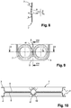
- a collecting space without passage 41 On the figure 5 is shown in section along a plane parallel to the section plane of the figure 3 , a collecting space without passage 41. It may be an upper collector space, or collector spaces located between the first and second passes or between the fifth and sixth passes.
- a partition 16 has been shown and is used for the elementary end paths thus making it possible to close off one end of a lower or upper collector, or else the end of the collector spaces 24 and 25 on the opposite side to the inserts. and 12 when such a partition is necessary to separate two adjacent collector spaces.
- the figure 5 is a sectional view according to VV of the figure 4 .
- the figure 6 is a sectional view according to VI-VI of the figure 4 .
- the passage 41 has been formed between the lower collecting spaces making it possible to pass from the front face 15 to the rear face 29, that is to say from the passage 33 to the passage 34.
- the passage 41 is offset in height relative to the corresponding lower collector spaces.
- the passage 41 can thus be shifted from a height of between 1.2 and 4.2 mm and towards the body of the elementary paths in the zz direction, in other words towards the upper collecting spaces.
- the higher pressure resistance is achieved by the fact that the brazed surface of the plates in contact between the passage 41 and the lower end of the plates 3 and 4 is increased.
- the compressive strength is maintained because of the sealed junction zone 8 and the inner spacer 40 brazed together and forming a relatively tight mesh.
- a passage similar to the passage 41 of the collector space can be made in the upper collector space.
- the passage is shifted in height to the corresponding lower collecting spaces.
- the passage 41 is formed by a bulge formed in the (es) plate (s) 3 and / or 4 of the tube 2.
- the bulge forming the passage 41 has a radius 'a' of between 8.5 and 10 mm.
- the bulge also includes fillet fillets 'b' having a radius of between 1 and 5 mm.
- the depth 'd' of the half passage 41 is less than the depth of the lower manifold to maintain a chute 42 for the evacuation of condensates, illustrated on the figure 10 .
- the chute 42 has a diameter of the order of 1 to 5 mm.
- the passage 41 allows the communication between two collecting spaces of a same tube 2.
- the area of a passage 41 may be between 60% and 80% of the area of the first elementary paths 13 of the third pass 33 and preferably between 65% and 75% of the area of the first paths. elementary 13 of the third pass 33.
- the thickness of an elementary path along the length of the heat exchanger 1 is less than 1.5 mm, preferably between 1 and 1.3 mm.
- the internal dimension of a collector is less than 45 mm, preferably between 35 and 40 mm.
- an elementary path is associated with heat exchange pads 44 and 45 elongate in the direction of flow of the air to be cooled, that is to say the direction yy, transversely to the flow of the coolant.
- the heat exchange tabs 44 and 45 can be fixed by brazing respectively to the plates 3 and 4 of an elementary path.
- the heat exchange pads 44 and 45 may have a length in the direction of flow of air substantially equal to that of the plates 3 and 4.
- the thickness of the sheet may be between 0.04 and 0.08 mm.
- the corrugations have a generally rectangular shape with rounded edges elongated in the direction of flow of air.
- Each corrugation may have a height 'e', in contact with the plate 3 and / or 4, between 0.45 and 0.6 mm in the direction of flow of the coolant.
- the corrugations may have a width 'f' in the first direction of between 4.1 and 4.3 mm.
- the corrugations may have a pitch 'fp' in the third direction of between 1.2 and 1.3 mm.
- the heat exchange tabs 44 and 45 are provided with louvers 46 and 47 formed on either side of a flat surface forming a corrugation branch.
- the louvers 46 and 47 have opposite shapes alternately.
- the height of the louvers 46 and 47 may be between 0.3 and 0.45 mm in the direction of flow of the refrigerant.
- the louvers 46 and 47 are intended to promote heat exchange between the first fluid and the second fluid, generally air.
- each elementary path has an elongated cross section along the third direction.
- Interlayers may extend projecting from an outer wall of the first elementary paths in the second elementary paths.
- the collecting spaces may be tubular.
- the circulation of the first fluid in the first elementary paths of a tube can be carried out in opposite directions.
- An even number of passes may be distributed for a first portion of the upstream side in the flow direction of the second fluid and for a second portion of the downstream side in the flow direction of the second fluid.
- a pass may include first neighboring elementary paths and in the same direction of flow of the first fluid. The number of elementary paths of a pass can be increasing and decreasing in the direction of flow of the first fluid.
- the heat exchanger including an evaporator for a vehicle air conditioning loop, defines a combined path for a first fluid formed of a plurality of first elementary paths and a combined path for a second fluid formed of a plurality of second elementary paths.
- the first and second elementary paths are arranged alternately in a first direction so that each elementary path for one of the fluids is in thermal contact with at least one adjacent elementary path for the other fluid.
- Each first elementary path has an elongated configuration in a second direction.
- the first elementary paths are arranged in two layers offset relative to each other in a third direction.
- the first, second and third directions are substantially perpendicular to each other.
- Each second elementary path extends in the third direction from an input face to an output face. The first elementary journeys lead to respective collecting spaces arranged in two rows corresponding to the layers.
- the collecting spaces communicate in pairs to establish a combined path extending from an inlet manifold space to an outlet manifold space located at opposite ends of the exchanger in one direction.
- At least one transition space is provided between two collector spaces respectively belonging to the two rows so that, in the first elementary paths communicating directly with said two collector spaces, the first fluid flows from one elementary path to the other according to the third direction.
- a transition space forming a passage is provided between a collector of an upstream face and a collector of a downstream face in the direction of flow of the second fluid, said passage allowing the flow of the first fluid.
- the passage may be formed by a bulge formed in the plates of the first elementary paths.
- the heat exchanger with particularly thin sheets for the first elementary paths, for example of thickness less than 0.3 mm, advantageously less than or equal to 0.27 mm.
- an increase in the cooling capacity of the order of 6% is obtained for an air temperature of 30 degrees at a relative humidity of 60%.
- a drop in air temperature of about 1 degree can be obtained for air flows of between 250 and 600 kg / hour.
- the heat exchangers according to the invention find a particular application in the heating, ventilation and / or air-conditioning installations of motor vehicles, in particular in the production of heat exchangers for motor vehicles integrated in these installations.
- This may include engine cooling radiators, cockpit, condensers, gas coolers or air conditioning system evaporators, charge air coolers, etc.
Landscapes
- Engineering & Computer Science (AREA)
- Physics & Mathematics (AREA)
- Thermal Sciences (AREA)
- Mechanical Engineering (AREA)
- General Engineering & Computer Science (AREA)
- Heat-Exchange Devices With Radiators And Conduit Assemblies (AREA)
Claims (26)
- Wärmetauscher (1), insbesondere Verdampfer für eine Klimaanlage eines Fahrzeugs, welcher einen kombinierten Weg für ein erstes Fluid, der aus mehreren ersten elementaren Wegen (13, 14) gebildet ist, und einem kombinierten Weg für ein zweites Fluid, der aus mehreren zweiten elementaren Wegen gebildet ist, definiert, wobei die ersten und zweiten elementaren Wege abwechselnd in einer ersten Richtung derart angeordnet sind, dass jeder elementare Weg für eines der Fluide in thermischem Kontakt mit mindestens einem benachbarten elementaren Weg für das andere Fluid steht, wobei jeder erste elementare Weg (13, 14) eine längliche Auslegung in einer zweiten Richtung aufweist, wobei die ersten elementaren Wege (13, 14) aus Rohren (2) mit mindestens einer Wand mit einer Wanddicke von kleiner oder gleich 0,3 mm, vorzugsweise zwischen 0,24 mm und 0,28 mm, bestehen,
dadurch gekennzeichnet, dass die Rohre (2) Zirkulationskanäle des ersten Fluids mit einem hydraulischen Durchmesser von weniger als 1,2 mm, vorzugsweise zwischen 0,89 mm und 1,07 mm, definieren. - Tauscher nach Anspruch 1, wobei die Rohre (2) mit mindestens einem Zwischenwärmetauscher (44, 45) mit einer Höhe in der ersten Richtung von weniger als 5 mm, vorzugsweise zwischen 3 mm und 4,5 mm, gekuppelt sind.
- Tauscher nach Anspruch 2, wobei der Zwischenwärmetauscher (44, 45) eine Blechdicke zwischen 0,04 und 0,08 mm aufweist.
- Tauscher nach Anspruch 2 oder 3, wobei der Zwischenwärmetauscher (44, 45) Lamellen mit einer Höhe (e) zwischen 0,45 und 0,6 mm aufweist.
- Tauscher nach Anspruch 4, wobei die Lamellen des Zwischenwärmetauschers (44, 45) eine Breite (f) in der ersten Richtung zwischen 4,1 und 4,3 mm aufweisen.
- Tauscher nach Anspruch 4 oder 5, wobei die Lamellen des Zwischenwärmetauschers (44, 45) einen Abstand (fp) in der dritten Richtung zwischen 1,2 und 1,3 mm aufweisen.
- Tauscher nach einem der vorhergehenden Ansprüche, wobei die Wanddicke der Rohre (2) kleiner oder gleich 0,27 mm ist.
- Tauscher nach einem der vorhergehenden Ansprüche, wobei die Rohre (2) eine innere Höhe in der ersten Richtung aufweisen, die weniger als 1,5 mm, vorzugsweise zwischen 1 mm und 1,3 mm, beträgt.
- Tauscher nach einem der vorhergehenden Ansprüche, wobei zwei Durchgänge durch eine Passage (10) verbunden sind, die zwischen zwei Kollektorräumen angeordnet ist, und die Wände dieser Passagen durch Bleche (3, 4) gebildet werden, die den ersten elementaren Weg begrenzen.
- Tauscher nach einem der vorhergehenden Ansprüche, wobei die ersten elementaren Wege (13, 14) in einer ersten und einer zweiten Schicht in einer dritten Richtung angeordnet sind.
- Tauscher nach Anspruch 10, wobei jeder elementare Weg in Kollektorräume (17 bis 28) mündet, die mit ersten elementaren Wegen (13, 14) verbunden sind, wobei jeweils zwei Kollektorräume derart kommunizieren, dass ein kombinierter Weg festgelegt wird, der sich von einem Einlasskollektorraum (17) zu einem Auslasskollektorraum (28) erstreckt.
- Tauscher nach Anspruch 11, wobei der Einlasskollektorraum (17) und der Auslasskollektorraum (28) jeweils in der ersten Schicht und in der zweiten Schicht des Tauschers angeordnet sind.
- Tauscher nach einem der Ansprüche 10 bis 12, wobei die ersten elementaren Wege (13, 14) einer Schicht in einer ersten Richtung voneinander versetzt sind.
- Tauscher nach einem der Ansprüche 10 bis 13, wobei mindestens ein Übergangsraum (41) zwischen zwei Kollektorräumen (22, 23) angeordnet ist, die jeweils zu den zwei Schichten gehören, so dass das erste Fluid der ersten Schicht zu der zweiten Schicht zirkuliert.
- Tauscher nach Anspruch 14, wobei die Fläche des Übergangsraums (41) zwischen 60 % und 80 % der Fläche der ersten elementaren Wege des dritten Durchgangs (33), vorzugsweise zwischen 65 % und 75 %, beträgt.
- Tauscher nach Anspruch 14 oder 15, wobei mindestens ein erster elementarer Weg, der an jedem Ende des Wärmetauschers (1) in der ersten Richtung angeordnet ist, keinen Übergangsraum (41) aufweist.
- Tauscher nach einem der Ansprüche 14 bis 16, wobei der Übergangsraum (41) aus einer Ausbuchtung der Bleche gebildet ist, wobei die Ausbuchtung einen Radius zwischen 8,5 mm und 10 mm aufweist.
- Tauscher nach einem der Ansprüche 14 bis 17, wobei der Übergangsraum (41) in Bezug auf den benachbarten Kollektorraum in der zweiten Richtung zu dem Kollektorraum entgegengesetzt zu demselben Durchgang versetzt ist.
- Tauscher nach einem der vorhergehenden Ansprüche, wobei jeder erste elementare Weg (13, 14) einen inneren Zwischenraum (40) umfasst.
- Tauscher nach Anspruch 19, wobei der Einsatz Kanäle mit einer allgemeinen Trapezform bildet.
- Tauscher nach einem der Ansprüche 19 oder 20, wobei die Dicke des inneren Zwischenraums (40) weniger als 0,1 mm, vorzugsweise zwischen 0,04 mm und 0,08 mm, beträgt.
- Tauscher nach einem der Ansprüche 19 bis 21, wobei der Abstand des inneren Zwischenraums (40) zwischen 1 mm und 1,4 mm liegt.
- Tauscher nach einem der Ansprüche 20 bis 22, wobei die große Basis des inneren Zwischenraums (40) zwischen 120 % und 140 % des Abstands, vorzugsweise zwischen 128 % und 140 % des Abstands, beträgt.
- Tauscher nach einem der Ansprüche 20 bis 23, wobei die kleine Basis des inneren Zwischenraums (40) zwischen 60 % und 80 % des Abstands, vorzugsweise zwischen 60 % und 72 % des Abstands, beträgt.
- Tauscher nach einem der Ansprüche 20 bis 24, wobei der Krümmungsradius des inneren Zwischenraums (40) zwischen 0,15 mm und 0,25 mm beträgt.
- Tauscher nach einem der vorhergehenden Ansprüche, wobei zwei erste elementare Wege desselben Rangs innerhalb der beiden Schichten durch zwei Bleche (3, 4) gebildet sind, die an ihren verlängerten Rändern in der zweiten Richtung und an ihrer Mitte zusammengefügt sind.
Applications Claiming Priority (1)
| Application Number | Priority Date | Filing Date | Title |
|---|---|---|---|
| FR0801618A FR2929388B1 (fr) | 2008-03-25 | 2008-03-25 | Echangeur de chaleur a puissance frigorifique elevee |
Publications (2)
| Publication Number | Publication Date |
|---|---|
| EP2105693A1 EP2105693A1 (de) | 2009-09-30 |
| EP2105693B1 true EP2105693B1 (de) | 2017-04-12 |
Family
ID=39598400
Family Applications (1)
| Application Number | Title | Priority Date | Filing Date |
|---|---|---|---|
| EP09155369.3A Active EP2105693B1 (de) | 2008-03-25 | 2009-03-17 | Hochleistungwärmetauscher |
Country Status (5)
| Country | Link |
|---|---|
| EP (1) | EP2105693B1 (de) |
| JP (1) | JP2009236478A (de) |
| CN (1) | CN101598505B (de) |
| ES (1) | ES2626802T3 (de) |
| FR (1) | FR2929388B1 (de) |
Families Citing this family (6)
| Publication number | Priority date | Publication date | Assignee | Title |
|---|---|---|---|---|
| FR2966581B1 (fr) | 2010-10-25 | 2014-12-26 | Valeo Systemes Thermiques | Echangeur de chaleur avec alimentation en fluide laterale |
| FR2973106B1 (fr) | 2011-03-23 | 2013-03-29 | Valeo Systemes Thermiques | Renfort de liaison entre plaques d'un echangeur de chaleur |
| CN105650950A (zh) * | 2016-03-02 | 2016-06-08 | 河南新科隆电器有限公司 | 一种复合冷凝器 |
| JP6923294B2 (ja) * | 2016-03-14 | 2021-08-18 | ハイリマレリジャパン株式会社 | 熱交換器 |
| FR3064347A1 (fr) * | 2017-03-23 | 2018-09-28 | Valeo Systemes Thermiques | Evaporateur, notamment pour circuit de climatisation de vehicule automobile, et circuit de climatisation correspondant |
| CN107941066A (zh) * | 2017-11-20 | 2018-04-20 | 山东同创汽车散热装置股份有限公司 | 散热器的薄壁散热管及散热器芯体 |
Family Cites Families (14)
| Publication number | Priority date | Publication date | Assignee | Title |
|---|---|---|---|---|
| JP3048600B2 (ja) * | 1990-06-29 | 2000-06-05 | 昭和アルミニウム株式会社 | 凝縮器 |
| JP3459271B2 (ja) * | 1992-01-17 | 2003-10-20 | 株式会社デンソー | 自動車用空調装置のヒータコア |
| JPH08313183A (ja) * | 1995-05-16 | 1996-11-29 | Nippondenso Co Ltd | 熱交換器、および熱交換器用コルゲートフィンの製造方法 |
| FR2747462B1 (fr) | 1996-04-16 | 1998-06-12 | Valeo Climatisation | Evaporateur a pochettes empilees resistant a la pression |
| JP2001324290A (ja) * | 1999-06-04 | 2001-11-22 | Denso Corp | 冷媒蒸発器 |
| US6339937B1 (en) * | 1999-06-04 | 2002-01-22 | Denso Corporation | Refrigerant evaporator |
| FR2803376B1 (fr) * | 1999-12-29 | 2002-09-06 | Valeo Climatisation | Evaporateur a tubes plats empilees possedant deux boites a fluide opposees |
| FR2825791B1 (fr) * | 2001-06-07 | 2003-09-05 | Valeo Climatisation | Evaporateur de puissance frigorifique elevee pour boucle de climatisation de vehicule |
| JP4212306B2 (ja) * | 2002-06-18 | 2009-01-21 | 株式会社日本クライメイトシステムズ | 熱交換器のパイプ取付構造 |
| US20070199687A1 (en) * | 2004-03-11 | 2007-08-30 | Behr Gmbh & Co. Kg | Stacked-Plate Heat Exchanger |
| DE102004056557A1 (de) * | 2004-11-23 | 2006-05-24 | Behr Gmbh & Co. Kg | Dimensionsoptimierte Vorrichtung zum Austausch von Wärme und Verfahren zur Optimierung der Dimensionen von Vorrichtungen zum Austausch von Wärme |
| JP2006226610A (ja) * | 2005-02-17 | 2006-08-31 | T Rad Co Ltd | コルゲートフィン型熱交換器コア |
| JP4761790B2 (ja) * | 2005-02-28 | 2011-08-31 | カルソニックカンセイ株式会社 | 蒸発器 |
| JP2007125590A (ja) * | 2005-11-04 | 2007-05-24 | Denso Corp | 熱交換器および熱交換器の製造方法 |
-
2008
- 2008-03-25 FR FR0801618A patent/FR2929388B1/fr not_active Expired - Fee Related
-
2009
- 2009-03-17 ES ES09155369.3T patent/ES2626802T3/es active Active
- 2009-03-17 EP EP09155369.3A patent/EP2105693B1/de active Active
- 2009-03-25 CN CN2009101497720A patent/CN101598505B/zh active Active
- 2009-03-25 JP JP2009074029A patent/JP2009236478A/ja active Pending
Non-Patent Citations (1)
| Title |
|---|
| None * |
Also Published As
| Publication number | Publication date |
|---|---|
| CN101598505B (zh) | 2013-11-27 |
| EP2105693A1 (de) | 2009-09-30 |
| CN101598505A (zh) | 2009-12-09 |
| FR2929388B1 (fr) | 2015-04-17 |
| ES2626802T3 (es) | 2017-07-26 |
| JP2009236478A (ja) | 2009-10-15 |
| FR2929388A1 (fr) | 2009-10-02 |
Similar Documents
| Publication | Publication Date | Title |
|---|---|---|
| EP1192402B1 (de) | Wärmetauscher mit mehrkanalrohren | |
| EP1592930B1 (de) | Kondensator, insbesondere f r einenkraftfahrzeugluftklimatisierungskreislauf | |
| EP2105693B1 (de) | Hochleistungwärmetauscher | |
| EP2689205B1 (de) | Anschlussbewehrung zwischen platten eines wärmetauschers | |
| EP2208955B1 (de) | Wärmeaustauschrippe für ein Wärmeaustauschsystem | |
| EP2294348A1 (de) | Plattenwärmetauscher, insbesondere für kraftfahrzeuge | |
| FR2798990A1 (fr) | Double echangeur de chaleur pour conditionneur d'air de vehicule | |
| EP2105694A1 (de) | Wàrmetauscherplatte | |
| EP2912396B1 (de) | Wärmetauscher, insbesondere für ein kraftfahrzeug | |
| WO2013011136A1 (fr) | Echangeur thermique, tube plat et plaque correspondants | |
| EP1762808A1 (de) | Kreislaufelement mit Flachrohren und Wärmetauscher mit demselben | |
| EP3289302B1 (de) | Wärmetauscher mit plattenstapel | |
| EP2810009A1 (de) | Kühler für ein fahrzeug, insbesondere ein kraftfahrzeug | |
| FR2852383A1 (fr) | Boite collectrice pour echangeur de chaleur a haute pression et echangeur de chaleur comportant cette boite collectrice | |
| FR2929387A1 (fr) | Echangeur de chaleur a resistance a la pression amelioree | |
| WO2010119100A1 (fr) | Tube de circulation de fluide réfrigérant, faisceau d'échange de chaleur et échangeur de chaleur comportant de tels tubes | |
| US11340027B2 (en) | Tube for a heat exchanger, and method of making the same | |
| WO2005031237A2 (fr) | Element de circuit pour échangeur de chaleur , et échangeur de chaleur ainsi obtenu | |
| FR2980739A1 (fr) | Tube de radiateur de refroidissement pour vehicule automobile et radiateur de refroidissement pour vehicule automobile comprenant un tel tube. | |
| EP1265045B1 (de) | Verdampfer mit hoher Kälteleistung für Kraftfahrzeugklimaanlage | |
| FR2850740A1 (fr) | Echangeur de chaleur a plaques a haute tenue a la pression, en particulier pour circuit de climation de vehicule automobile | |
| EP1546627B1 (de) | Plattenwärmetauscher, insbesondere für kraftfahrzeuge | |
| FR3160764A1 (fr) | Echangeur de chaleur comportant une pluralité de plaques empilées | |
| WO2016198536A1 (fr) | Echangeur de chaleur pour vehicule automobile | |
| FR2989766A1 (fr) | Faisceau d'echange de chaleur pour echangeur de chaleur et echangeur de chaleur comprenant ledit faisceau |
Legal Events
| Date | Code | Title | Description |
|---|---|---|---|
| PUAI | Public reference made under article 153(3) epc to a published international application that has entered the european phase |
Free format text: ORIGINAL CODE: 0009012 |
|
| AK | Designated contracting states |
Kind code of ref document: A1 Designated state(s): AT BE BG CH CY CZ DE DK EE ES FI FR GB GR HR HU IE IS IT LI LT LU LV MC MK MT NL NO PL PT RO SE SI SK TR |
|
| AX | Request for extension of the european patent |
Extension state: AL BA RS |
|
| 17P | Request for examination filed |
Effective date: 20100325 |
|
| 17Q | First examination report despatched |
Effective date: 20100428 |
|
| AKX | Designation fees paid |
Designated state(s): AT BE BG CH CY CZ DE DK EE ES FI FR GB GR HR HU IE IS IT LI LT LU LV MC MK MT NL NO PL PT RO SE SI SK TR |
|
| GRAP | Despatch of communication of intention to grant a patent |
Free format text: ORIGINAL CODE: EPIDOSNIGR1 |
|
| INTG | Intention to grant announced |
Effective date: 20161014 |
|
| GRAS | Grant fee paid |
Free format text: ORIGINAL CODE: EPIDOSNIGR3 |
|
| GRAA | (expected) grant |
Free format text: ORIGINAL CODE: 0009210 |
|
| AK | Designated contracting states |
Kind code of ref document: B1 Designated state(s): AT BE BG CH CY CZ DE DK EE ES FI FR GB GR HR HU IE IS IT LI LT LU LV MC MK MT NL NO PL PT RO SE SI SK TR |
|
| REG | Reference to a national code |
Ref country code: GB Ref legal event code: FG4D Free format text: NOT ENGLISH |
|
| REG | Reference to a national code |
Ref country code: CH Ref legal event code: EP |
|
| REG | Reference to a national code |
Ref country code: IE Ref legal event code: FG4D Free format text: LANGUAGE OF EP DOCUMENT: FRENCH |
|
| REG | Reference to a national code |
Ref country code: AT Ref legal event code: REF Ref document number: 884337 Country of ref document: AT Kind code of ref document: T Effective date: 20170515 |
|
| REG | Reference to a national code |
Ref country code: DE Ref legal event code: R096 Ref document number: 602009045337 Country of ref document: DE |
|
| REG | Reference to a national code |
Ref country code: ES Ref legal event code: FG2A Ref document number: 2626802 Country of ref document: ES Kind code of ref document: T3 Effective date: 20170726 |
|
| REG | Reference to a national code |
Ref country code: NL Ref legal event code: MP Effective date: 20170412 |
|
| REG | Reference to a national code |
Ref country code: LT Ref legal event code: MG4D |
|
| REG | Reference to a national code |
Ref country code: AT Ref legal event code: MK05 Ref document number: 884337 Country of ref document: AT Kind code of ref document: T Effective date: 20170412 |
|
| PG25 | Lapsed in a contracting state [announced via postgrant information from national office to epo] |
Ref country code: NL Free format text: LAPSE BECAUSE OF FAILURE TO SUBMIT A TRANSLATION OF THE DESCRIPTION OR TO PAY THE FEE WITHIN THE PRESCRIBED TIME-LIMIT Effective date: 20170412 |
|
| PG25 | Lapsed in a contracting state [announced via postgrant information from national office to epo] |
Ref country code: AT Free format text: LAPSE BECAUSE OF FAILURE TO SUBMIT A TRANSLATION OF THE DESCRIPTION OR TO PAY THE FEE WITHIN THE PRESCRIBED TIME-LIMIT Effective date: 20170412 Ref country code: FI Free format text: LAPSE BECAUSE OF FAILURE TO SUBMIT A TRANSLATION OF THE DESCRIPTION OR TO PAY THE FEE WITHIN THE PRESCRIBED TIME-LIMIT Effective date: 20170412 Ref country code: LT Free format text: LAPSE BECAUSE OF FAILURE TO SUBMIT A TRANSLATION OF THE DESCRIPTION OR TO PAY THE FEE WITHIN THE PRESCRIBED TIME-LIMIT Effective date: 20170412 Ref country code: GR Free format text: LAPSE BECAUSE OF FAILURE TO SUBMIT A TRANSLATION OF THE DESCRIPTION OR TO PAY THE FEE WITHIN THE PRESCRIBED TIME-LIMIT Effective date: 20170713 Ref country code: HR Free format text: LAPSE BECAUSE OF FAILURE TO SUBMIT A TRANSLATION OF THE DESCRIPTION OR TO PAY THE FEE WITHIN THE PRESCRIBED TIME-LIMIT Effective date: 20170412 Ref country code: NO Free format text: LAPSE BECAUSE OF FAILURE TO SUBMIT A TRANSLATION OF THE DESCRIPTION OR TO PAY THE FEE WITHIN THE PRESCRIBED TIME-LIMIT Effective date: 20170712 |
|
| PG25 | Lapsed in a contracting state [announced via postgrant information from national office to epo] |
Ref country code: LV Free format text: LAPSE BECAUSE OF FAILURE TO SUBMIT A TRANSLATION OF THE DESCRIPTION OR TO PAY THE FEE WITHIN THE PRESCRIBED TIME-LIMIT Effective date: 20170412 Ref country code: BG Free format text: LAPSE BECAUSE OF FAILURE TO SUBMIT A TRANSLATION OF THE DESCRIPTION OR TO PAY THE FEE WITHIN THE PRESCRIBED TIME-LIMIT Effective date: 20170712 Ref country code: SE Free format text: LAPSE BECAUSE OF FAILURE TO SUBMIT A TRANSLATION OF THE DESCRIPTION OR TO PAY THE FEE WITHIN THE PRESCRIBED TIME-LIMIT Effective date: 20170412 Ref country code: IS Free format text: LAPSE BECAUSE OF FAILURE TO SUBMIT A TRANSLATION OF THE DESCRIPTION OR TO PAY THE FEE WITHIN THE PRESCRIBED TIME-LIMIT Effective date: 20170812 Ref country code: PL Free format text: LAPSE BECAUSE OF FAILURE TO SUBMIT A TRANSLATION OF THE DESCRIPTION OR TO PAY THE FEE WITHIN THE PRESCRIBED TIME-LIMIT Effective date: 20170412 |
|
| REG | Reference to a national code |
Ref country code: DE Ref legal event code: R097 Ref document number: 602009045337 Country of ref document: DE |
|
| PG25 | Lapsed in a contracting state [announced via postgrant information from national office to epo] |
Ref country code: DK Free format text: LAPSE BECAUSE OF FAILURE TO SUBMIT A TRANSLATION OF THE DESCRIPTION OR TO PAY THE FEE WITHIN THE PRESCRIBED TIME-LIMIT Effective date: 20170412 Ref country code: SK Free format text: LAPSE BECAUSE OF FAILURE TO SUBMIT A TRANSLATION OF THE DESCRIPTION OR TO PAY THE FEE WITHIN THE PRESCRIBED TIME-LIMIT Effective date: 20170412 Ref country code: RO Free format text: LAPSE BECAUSE OF FAILURE TO SUBMIT A TRANSLATION OF THE DESCRIPTION OR TO PAY THE FEE WITHIN THE PRESCRIBED TIME-LIMIT Effective date: 20170412 Ref country code: EE Free format text: LAPSE BECAUSE OF FAILURE TO SUBMIT A TRANSLATION OF THE DESCRIPTION OR TO PAY THE FEE WITHIN THE PRESCRIBED TIME-LIMIT Effective date: 20170412 |
|
| PLBE | No opposition filed within time limit |
Free format text: ORIGINAL CODE: 0009261 |
|
| STAA | Information on the status of an ep patent application or granted ep patent |
Free format text: STATUS: NO OPPOSITION FILED WITHIN TIME LIMIT |
|
| 26N | No opposition filed |
Effective date: 20180115 |
|
| REG | Reference to a national code |
Ref country code: FR Ref legal event code: PLFP Year of fee payment: 10 |
|
| PG25 | Lapsed in a contracting state [announced via postgrant information from national office to epo] |
Ref country code: SI Free format text: LAPSE BECAUSE OF FAILURE TO SUBMIT A TRANSLATION OF THE DESCRIPTION OR TO PAY THE FEE WITHIN THE PRESCRIBED TIME-LIMIT Effective date: 20170412 |
|
| PG25 | Lapsed in a contracting state [announced via postgrant information from national office to epo] |
Ref country code: MT Free format text: LAPSE BECAUSE OF FAILURE TO SUBMIT A TRANSLATION OF THE DESCRIPTION OR TO PAY THE FEE WITHIN THE PRESCRIBED TIME-LIMIT Effective date: 20170412 |
|
| REG | Reference to a national code |
Ref country code: CH Ref legal event code: PL |
|
| GBPC | Gb: european patent ceased through non-payment of renewal fee |
Effective date: 20180317 |
|
| PG25 | Lapsed in a contracting state [announced via postgrant information from national office to epo] |
Ref country code: MC Free format text: LAPSE BECAUSE OF FAILURE TO SUBMIT A TRANSLATION OF THE DESCRIPTION OR TO PAY THE FEE WITHIN THE PRESCRIBED TIME-LIMIT Effective date: 20170412 |
|
| REG | Reference to a national code |
Ref country code: BE Ref legal event code: MM Effective date: 20180331 |
|
| REG | Reference to a national code |
Ref country code: IE Ref legal event code: MM4A |
|
| PG25 | Lapsed in a contracting state [announced via postgrant information from national office to epo] |
Ref country code: LU Free format text: LAPSE BECAUSE OF NON-PAYMENT OF DUE FEES Effective date: 20180317 |
|
| PG25 | Lapsed in a contracting state [announced via postgrant information from national office to epo] |
Ref country code: IE Free format text: LAPSE BECAUSE OF NON-PAYMENT OF DUE FEES Effective date: 20180317 |
|
| PG25 | Lapsed in a contracting state [announced via postgrant information from national office to epo] |
Ref country code: BE Free format text: LAPSE BECAUSE OF NON-PAYMENT OF DUE FEES Effective date: 20180331 Ref country code: CH Free format text: LAPSE BECAUSE OF NON-PAYMENT OF DUE FEES Effective date: 20180331 Ref country code: LI Free format text: LAPSE BECAUSE OF NON-PAYMENT OF DUE FEES Effective date: 20180331 Ref country code: GB Free format text: LAPSE BECAUSE OF NON-PAYMENT OF DUE FEES Effective date: 20180317 |
|
| PG25 | Lapsed in a contracting state [announced via postgrant information from national office to epo] |
Ref country code: TR Free format text: LAPSE BECAUSE OF FAILURE TO SUBMIT A TRANSLATION OF THE DESCRIPTION OR TO PAY THE FEE WITHIN THE PRESCRIBED TIME-LIMIT Effective date: 20170412 |
|
| PG25 | Lapsed in a contracting state [announced via postgrant information from national office to epo] |
Ref country code: PT Free format text: LAPSE BECAUSE OF FAILURE TO SUBMIT A TRANSLATION OF THE DESCRIPTION OR TO PAY THE FEE WITHIN THE PRESCRIBED TIME-LIMIT Effective date: 20170412 Ref country code: HU Free format text: LAPSE BECAUSE OF FAILURE TO SUBMIT A TRANSLATION OF THE DESCRIPTION OR TO PAY THE FEE WITHIN THE PRESCRIBED TIME-LIMIT; INVALID AB INITIO Effective date: 20090317 |
|
| PG25 | Lapsed in a contracting state [announced via postgrant information from national office to epo] |
Ref country code: CY Free format text: LAPSE BECAUSE OF FAILURE TO SUBMIT A TRANSLATION OF THE DESCRIPTION OR TO PAY THE FEE WITHIN THE PRESCRIBED TIME-LIMIT Effective date: 20170412 Ref country code: MK Free format text: LAPSE BECAUSE OF NON-PAYMENT OF DUE FEES Effective date: 20170412 |
|
| PGFP | Annual fee paid to national office [announced via postgrant information from national office to epo] |
Ref country code: CZ Payment date: 20210219 Year of fee payment: 13 Ref country code: IT Payment date: 20210311 Year of fee payment: 13 |
|
| PGFP | Annual fee paid to national office [announced via postgrant information from national office to epo] |
Ref country code: ES Payment date: 20210412 Year of fee payment: 13 |
|
| PG25 | Lapsed in a contracting state [announced via postgrant information from national office to epo] |
Ref country code: CZ Free format text: LAPSE BECAUSE OF NON-PAYMENT OF DUE FEES Effective date: 20220317 |
|
| REG | Reference to a national code |
Ref country code: ES Ref legal event code: FD2A Effective date: 20230503 |
|
| PG25 | Lapsed in a contracting state [announced via postgrant information from national office to epo] |
Ref country code: IT Free format text: LAPSE BECAUSE OF NON-PAYMENT OF DUE FEES Effective date: 20220317 |
|
| P01 | Opt-out of the competence of the unified patent court (upc) registered |
Effective date: 20230528 |
|
| PG25 | Lapsed in a contracting state [announced via postgrant information from national office to epo] |
Ref country code: ES Free format text: LAPSE BECAUSE OF NON-PAYMENT OF DUE FEES Effective date: 20220318 |
|
| PGFP | Annual fee paid to national office [announced via postgrant information from national office to epo] |
Ref country code: FR Payment date: 20250331 Year of fee payment: 17 |
|
| PGFP | Annual fee paid to national office [announced via postgrant information from national office to epo] |
Ref country code: DE Payment date: 20260313 Year of fee payment: 18 |