EP0186621B1 - Verfahren und Vorrichtung zum chemischen Reinigen - Google Patents
Verfahren und Vorrichtung zum chemischen Reinigen Download PDFInfo
- Publication number
- EP0186621B1 EP0186621B1 EP85730174A EP85730174A EP0186621B1 EP 0186621 B1 EP0186621 B1 EP 0186621B1 EP 85730174 A EP85730174 A EP 85730174A EP 85730174 A EP85730174 A EP 85730174A EP 0186621 B1 EP0186621 B1 EP 0186621B1
- Authority
- EP
- European Patent Office
- Prior art keywords
- solvent
- solvents
- valve
- boiling point
- tank
- Prior art date
- Legal status (The legal status is an assumption and is not a legal conclusion. Google has not performed a legal analysis and makes no representation as to the accuracy of the status listed.)
- Expired - Lifetime
Links
- 238000000034 method Methods 0.000 title claims description 35
- 238000005108 dry cleaning Methods 0.000 title claims description 22
- 239000002904 solvent Substances 0.000 claims description 136
- 238000009835 boiling Methods 0.000 claims description 41
- 238000011084 recovery Methods 0.000 claims description 11
- 238000004821 distillation Methods 0.000 claims description 10
- 238000004140 cleaning Methods 0.000 claims description 4
- 238000004508 fractional distillation Methods 0.000 claims 3
- 239000000203 mixture Substances 0.000 claims 1
- 238000001035 drying Methods 0.000 description 18
- 238000005406 washing Methods 0.000 description 17
- XLYOFNOQVPJJNP-UHFFFAOYSA-N water Substances O XLYOFNOQVPJJNP-UHFFFAOYSA-N 0.000 description 15
- 241000779819 Syncarpia glomulifera Species 0.000 description 10
- 239000012046 mixed solvent Substances 0.000 description 10
- 239000001739 pinus spp. Substances 0.000 description 10
- 229940036248 turpentine Drugs 0.000 description 10
- 238000001816 cooling Methods 0.000 description 7
- 239000007788 liquid Substances 0.000 description 6
- 239000000463 material Substances 0.000 description 5
- CYTYCFOTNPOANT-UHFFFAOYSA-N Perchloroethylene Chemical group ClC(Cl)=C(Cl)Cl CYTYCFOTNPOANT-UHFFFAOYSA-N 0.000 description 4
- 239000000498 cooling water Substances 0.000 description 4
- 239000003712 decolorant Substances 0.000 description 4
- 238000012545 processing Methods 0.000 description 4
- 238000010586 diagram Methods 0.000 description 3
- UOCLXMDMGBRAIB-UHFFFAOYSA-N 1,1,1-trichloroethane Chemical compound CC(Cl)(Cl)Cl UOCLXMDMGBRAIB-UHFFFAOYSA-N 0.000 description 2
- OKTJSMMVPCPJKN-UHFFFAOYSA-N Carbon Chemical compound [C] OKTJSMMVPCPJKN-UHFFFAOYSA-N 0.000 description 2
- 206010020112 Hirsutism Diseases 0.000 description 2
- 238000013459 approach Methods 0.000 description 2
- 238000007796 conventional method Methods 0.000 description 2
- 238000002474 experimental method Methods 0.000 description 2
- 238000002156 mixing Methods 0.000 description 2
- 230000000704 physical effect Effects 0.000 description 2
- 230000009897 systematic effect Effects 0.000 description 2
- 230000007704 transition Effects 0.000 description 2
- 239000002253 acid Substances 0.000 description 1
- 239000000853 adhesive Substances 0.000 description 1
- 230000001070 adhesive effect Effects 0.000 description 1
- 239000003463 adsorbent Substances 0.000 description 1
- 125000001931 aliphatic group Chemical group 0.000 description 1
- PNEYBMLMFCGWSK-UHFFFAOYSA-N aluminium oxide Inorganic materials [O-2].[O-2].[O-2].[Al+3].[Al+3] PNEYBMLMFCGWSK-UHFFFAOYSA-N 0.000 description 1
- 230000000052 comparative effect Effects 0.000 description 1
- 238000009833 condensation Methods 0.000 description 1
- 230000005494 condensation Effects 0.000 description 1
- 238000002845 discoloration Methods 0.000 description 1
- 230000000694 effects Effects 0.000 description 1
- 238000005194 fractionation Methods 0.000 description 1
- 230000007774 longterm Effects 0.000 description 1
- 239000003960 organic solvent Substances 0.000 description 1
- 238000005192 partition Methods 0.000 description 1
- 238000000746 purification Methods 0.000 description 1
- 238000004904 shortening Methods 0.000 description 1
Images


Classifications
-
- D—TEXTILES; PAPER
- D06—TREATMENT OF TEXTILES OR THE LIKE; LAUNDERING; FLEXIBLE MATERIALS NOT OTHERWISE PROVIDED FOR
- D06F—LAUNDERING, DRYING, IRONING, PRESSING OR FOLDING TEXTILE ARTICLES
- D06F43/00—Dry-cleaning apparatus or methods using volatile solvents
- D06F43/08—Associated apparatus for handling and recovering the solvents
-
- D—TEXTILES; PAPER
- D06—TREATMENT OF TEXTILES OR THE LIKE; LAUNDERING; FLEXIBLE MATERIALS NOT OTHERWISE PROVIDED FOR
- D06F—LAUNDERING, DRYING, IRONING, PRESSING OR FOLDING TEXTILE ARTICLES
- D06F43/00—Dry-cleaning apparatus or methods using volatile solvents
Definitions
- the present invention relates to a dry cleaning method in which in a dry cleaner of using organic solvents such as perchloroethylene, 1,1,1,-trichloroethane, turpentine (oil series) and the like, the already used solvent is replaced with another solvent which is soluble therein and has a lower boiling point, for example, Furon R113 or R11, during washing or immediately before drying inorder to thereby shorten a drying period of time.
- organic solvents such as perchloroethylene, 1,1,1,-trichloroethane, turpentine (oil series) and the like
- the already used solvent is replaced with another solvent which is soluble therein and has a lower boiling point, for example, Furon R113 or R11, during washing or immediately before drying inorder to thereby shorten a drying period of time.
- the most proper washing method can be chosen for the greater part of materials, processings and morphologies of clothes, and troubles of clothes due to washing can be reduced remarkably.
- the invention relates further to a dry cleaning apparatus. While FR-A-987 567 discloses the use of different solvents for better understanding of the present invention a conventional dry cleaning technique, known from the practice, using solvents other than turpentine will be described in reference to Fig. 6.
- a conventional dry cleaning technique known from the practice, using solvents other than turpentine will be described in reference to Fig. 6.
- clothes 2 are thrown into a treating tank 10 by opening a door 1, and after the door 1 has been shut, the operation of the dry cleaner is begun. Afterward, a cleaning treatment generally makes progress in the following order.
- a solvent 4 is pumped up from a solvent tank 3 via a valve 5 by means of a pump 6 and is delivered in a predetermined amount to the treating tank 10 through a route consisting of a valve 7 and a filter 8 or a route consisting of a valve 9.
- a treating drum 11 is slowly rotated, and the solvent 4 is then circulated through a circuit consisting of the treating tank 10, a button trap 12, a valve 13, the pump 6, the valve 7, the filter 8 or the valve 9 in order to wash the clothes 2.
- the solvent 4 is discharged through a route consisting of the treating tank 10, the button trap 12, the valve 13, the pump 6, a valve 14 and a distiller 15. Afterward, the treating drum 11 is rotated at a high speed to centrifuge the solvent 4 present in the clothes 2, and the centrifuged solvent 4 is then discharged in like manner.
- the solvent 4 is discharged to the solvent tank 3 through the treating tank 10, the button trap 12, the valve 13 and the valve 5. Afterward, the treating drum 11 is rotated at a high speed to centrifuge the solvent 4 present in the clothes 2, and the centrifuged solvent 4 is discharged therefrom.
- the treating drum 11 is slowly rotated again, and air is circulated in the direction of an arrow 20 between the treating tank 10 and a recovery air duct 19 consisting of a fan 16, an air cooler 17 and an air heater 18, whereby the clothes 2 are dried.
- a solvent gas vaporized from the clothes 2 is condensed in an air cooler 17, is then delivered to a water separator 22 via a recovery passage 21, and is afterward introduced into a clean tank 24 through a solvent pipe 23.
- dumpers 25, 26 are opened as depicted by dotted lines in the drawing, and fresh air is taken in through the dumper 25. Further, the uncondensed solvent gas which has not been recovered in the air cooler 17 is discharged through the dumper 26 in order to take away the odor of the solvent in the clothes 2.
- the solvent 4 forwarded to the distiller 15 in the preceding process (3) is evaporated, and is then condensed in a condenser 27.
- the condensed solvent 4 is introduced into the clean tank 24 through the water separator 22 and the solvent pipe 23 and is then returned to the solvent tank 3 over an overflow partition 28.
- the water separated by the water separator 22 is discharged from the system through a water pipe 29.
- turpentine dry cleaning apparatus is composed of a washing and desolvating tank 100 shown in Fig. 7, which is similar to the treating tank shown in Fig. 6, and a drying exclusive tank 200 in Fig. 8 (which is called a tumbler).
- a washing and desolvating tank 100 the same procedure as the above-mentioned washing processes (1), (2) and (5) of using the other solvent is taken, whereby all the processes are over.
- the turpentine dry cleaning method generally contains no distillation process, and in many cases, the purification of the solvent 4 is carried out by using a filter 8a which is packed with an aliphatic acid adsorbent such as porous alumina and a decolorant such as activated carbon.
- the desolvated clothes 2 are taken out by opening the door 1, and after the opening of a door 1a of the tumbler shown in Fig. 8, they are thrown into a treating tank 10a.
- the outside air 20a is taken in through an inlet duct 19a by a fan 16 and is heated by an air heater 18, and the heated air is then delivered to the treating tank 10a.
- the solvent 4 in the clothes 2 is evaporated and is then discharged from the system (to the outdoors) through an outlet duct 19a, whereby drying is over.
- Table 1 compares typical physical properties of the solvents often used presently. Further, Table 2 compares features, restrictions, faults and the like of the solvents regarding the dry cleaning on the basis of their physical properties shown in Table 1.
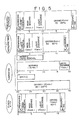
- Fig. 5 compares general washing and drying processes in the cases of using perchloroethylene, 1,1,1-trichloroethane, turpentine (oil series) and Furon R113 which are now widely employed.
- all the methods, except for the Furon R113 method take about 50% of the whole treatment time to accomplish drying, which fact is an obstacle to recent needs of shortening the treatment time.
- the dry tumbling for a long period of time has bad influence on the chlothes at times, and for example, hairiness and shrinkage of the clothes tend to be caused thereby.
- the KB values in Table 1 are scales for representing relative dissolving powers of the solvents.
- An object of the present invention is to provide a dry cleaning method and apparatus which can apply to varied materials, processings, morphologies of clothes.
- Still another object of the present invention is to provide a dry cleaning method by which there can be overcome problems such as hairiness and shrinkage due to a long-term drying in a conventional dry cleaning process.
- Two or more solvents can be used in optional ratios in one dry cleaner, and thus the most proper washing method can be chosen for the greater part of materials, processings and morphologies of clothes. Further, it is possible to remarkably reduce troubles (faulty washing, creases, shrinkages, discoloration, deformation, removal of adhesive materials, and the like) regarding a washing technique. Also in points of occupation space, fund for facilities, volume of facilities and maintenace cost, the present invention has great advantages.
- Fig. 1 is a systematic view illustrating a first embodiment of a dry cleaning apparatus regarding the present invention
- Fig. 2 is a circuit diagram illustrating a fractionating system used in the first embodiment of the present invention
- Fig. 3 is a circuit diagram illustrating a usage of specific filters containing a deoxidizer and a decolorant which are often used in the first embodiment of the present invention in which turpentine is employed;
- Fig. 4 is a diagram showing a relation between a drying time and a solvent condensation recovery rate in an air cooler in a second embodiment of the present invention in which the apparatus in Fig. 1 is employed;
- Fig. 5 is a comparative illustrative view of washing and drying processes by the use of various usual solvents such as perchloroethylene and the like;
- Fig. 6 is a systematic view of a conventional dry cleaner
- Figs. 7 and 8 are illustrative views of a conventional dry cleaning process of using turpentine.
- FIGs. 1 to 3 show a first embodiment of the present invention.
- these drawings exemplarily show exclusive solvent tanks for two kinds of solvents and a fractionating device or a filter structure, but needless to say, they can serve for three or more kinds of solvents in all the same volume.
- a first difference is that a first solvent receiving tank 3 and a second solvent receiving tank 3a are disposed independently of each other and they are provided with exclusive valves 5 and 5a, respectively.
- valves 32, 32a which are adjustable in compliance with boiling points inherent in solvents or by a program control are disposed on a condensed solvent flow pipe 34 connecting to water separators 22, 22a; solvent pipes 23, 23a and water pipes 29, 29a are provided; and a safety valve 33 is additionally disposed on a condenser 27.
- a third difference is that a recovery passage 21 extending from an air cooler 17 is connected to the water separator 22 or 22a via a valve 30 or 30a and is connected to a distiller 15 via a non-return valve 31.
- Fig. 1 is about the same as in Fig. 6. It can be naturally conceived to exclusively provide each pump 6 for each solvent, but for simplification, one pump 6 is here used in common.
- Fig. 2 shows a constitutional example of a condenser capable of completely recovering the two kinds of solvents by fractionation.
- a riser 36 on the distiller 15 (Fig. 1) is connected to a first condenser 27a in which a cooling coil 41 is disposed.
- a temperature of this cooling coil 41 is adjusted to a level equal to or 2 to 3°C higher than a lower boiling point of the two solvents by means of a control system not shown.
- a gas pipe 37 is connected to the bottom of the condenser 27a and a liquid pipe 38 branches off from the gas pipe 37.
- This liquid pipe 38 is dipped in a tank 35 filled with a cooling water 40a in a low-temperature cooling coil 40 and is further connected to the water separator 22a (Fig. 1).
- the above-mentioned gas pipe 37 is connected to a second condenser 27b, where there is disposed the low-temperature cooling coil 40 which has been cooled to a temprature enough to condense the low boiling point solvent. Further, a liquid pipe 39 extends downward from the bottom of the condenser 27b and is connected to the water separator 22 (Fig. 1).
- Fig. 3 is a constitutional example of specific filers containing a deoxidizer and a decolorant which have often been used in a turpentine (oil series) dry cleaning system.
- Filters 8a, 8a-1 and 8b in this drawing are all the especial filters, and these filters are equipped with exclusive valves 7a, 7a-1 and 7b and non-return valves 50, 50a, 50b, respectively. Further, these filters are connected to a pipe in parallel.
- the opening and shutting of the valves 32, 32a disposed on the condensed solvent flow pipe 34 extending from the condenser 27 are, controlled by the program control system (not shown) in compliance with the kinds of solvents, or alternatively these vavles 32, 32a are opened or shut by detecting a temperature of the solvent in the distiller 15 with the aid of a temperature sensor (not shown) in order to avoid mixing the solvents 4, 4a with each other.
- the solvents 4, 4a flow into the exclusive tanks 3, 3a, respectively.
- the one distiller is disposed in this embodiment, but needless to say, a plurality of distillers may be provided for the respective solvents.
- the first solvent 4 is pumped up from the tank 3 via the valve 5 by means of the pump 6 and is delivered in a predetermined amount to the treating tank 10 through the valve 7 and the filter 8 or through the valve 9.
- the second solvent 4a is pumped up from the tank 3a via the valve 5a in like manner.
- a treating drum 11 is slowly rotated, and a mixed solvent (4 + 4a) is circulated through a circuit consisting of the treating tank 10, a button trap 12, a valve 13, the pump 6, the valve 7 and the filter 8 or the valve 9.
- the mixed solvent (4 + 4a) is discharged through a route consisting of the treating tank 10, the button trap 12, the valve 13, the pump 6, a valve 14 and the distiller 15. Afterward, the treating drum 11 is rotated at a high speed to centrifuge the solvent (4 + 4a)present in the clothes 2, and the centrifuged solvent (4 + 4a) is discharged in like manner.
- the treating drum 11 is slowly rotated again, and air is circulated in the direction of an arrow 20 between the treating tank 10 and a recovery air duct 19 consisting of a fan 16, the air cooler 17 and an air heater 18, whereby the clothes 2 are dried.
- a solvent gas vaporized from the clothes 2 is condensed in the air cooler 17 and is delivered to the distiller 15 through the recovery circuit 21 containing the non-return valve 31.
- dumpers 25, 26 are opened as depicted by dotted lines in the drawing, and fresh air is taken in through the dumper 25. Further, the uncondensed solvent gas whick has not been recovered by the air cooler 17 is discharged through the dumper 26 in order to take away the odor of the solvent in the clothes 2.
- the mixed solvent (4 + 4a) forwarded to the distiller 15 in the preceding processes (3), (4) and (5) is distilled at a lower boiling point (for example, of the solvent 4) of the respective solvents, and is caused to pass through a condenser 27.
- the mixed solvent condensed therein is then introduced into the water separator 22 via the valve 32 opened under a control of a distillation temperature sensor (not shown), and is further returned to the solvent tank 3 through a solvent pipe 23.
- the distillation temperature sensor (not shown) operates in the same manner as described above, in order to open the valve 32a (the valve 32 is shut), thereby recovering the high boiling point solvent 4a in the tank 3a in the same manner as described above (a solvent of an intermediate component in the transition from the low boiling point solvent to the high boiling point solvent is as small as trace in experiments, and thus it has no problem in practice. In consequence, the intermediate solvent may be handled as the low or the high boiling point solvent).
- the low boiling point solvent 4 evaporated in the distiller 15 (Fig. 1) is, to begin with, introduced into the first condenser 27a, but it is not condensed therein, because a temperature of the cooling water in the cooling coil 41 is higher than the boiling point of the low boiling point solvent. Therefore, the latter is delivered through the gas pipe 37 to the second condenser 27b, wherein it is condensed by the low-temperature cooling coil 40, and the condensed solvent then runs into the water separator 22 via the liquid pipe 39.
- the high boiling point solvent begins to evaporate, the recovery of the solvent in the first condenser 27a becomes possible, and the condensed solvent runs into the water separator 22a through the liquid pipe 38.
- the tank 35 which has been filled with the cooling water 40a of the low-temperature cooling coil 40 serves to cool the liquid pipe 38 dipped in the cooling water 40a.
- the filters 8a-1 and 8b are used exclusively.
- the valve 7a-1 alone is opened and the others are shut.
- the solvent 4 which has passed through the filter 8a-1 pushes the non-return valve 50a and runs into the treating tank 10 (Fig. 1).
- the filter 8a alone is used in the same manner as described above so that the solvent components in the filters 8a-1, 8b may not be changed.
- This embodiment of the present invention is about a dry cleaning method in which the dry cleaning apparatus shown in Fig. 1 is used, and a description will be given in reference to Fig. 1.
- first and second solvents 4 and 4a are regarded as a low boiling point solvent and a high boiling point solvent, respectively, the latter 4a will be replaced with the former 4 in the dry cleaning apparatus during washing. The procedure of this replacement will be first described.
- the high boiling point solvent 4a is pumped up from the tank 3 via the valve 5a by means of the pump 6 and is delivered in a predetermined amount to the treating tank 10 through the valve 7 and the filter 8 or through the valve 9.
- a treating drum 11 is slowly rotated, and the high boiling point solvent 4a is circulated through a circuit consisting of the treating tank 10, the button trap 12, the valve 13, the pump 6, the valve 7, the filter 8 or the valve 9, in order to wash the clothes 2.
- the solvent 4a is discharged through the treating tank 10, the button trap 12, the valve 13, the pump 6, the valve 14 and the distiller 15. Afterward, the treating drum 11 is rotated at a high speed to centrifuge the high boiling point solvent 4a present in the clothes 2, and the centrifuged solvent 4a is discharged in like manner.
- the low boiling point solvent 4 is pumped up from the tank 3 via the valve 5a by means of the pump 6 and is delivered in a predetermined amount to the treating tank 10 through the valve 7 and the filter 8 or through the valve 9.
- the treating drum 11 is slowly rotated again, and air is circulated in the direction of an arrow 20 between the treating tank 10 and the recovery air duct 19 consisting of the fan 16, the air cooler 17 and the air heater 18, whereby the clothes 2 are dried.
- a solvent gas vaporized from the clothes 2 is condensed in the air cooler 17 and is then delivered to the distiller 15 through the recovery circuit 21 having the non-return valve 31.
- dumpers 25, 26 are opened as depicted by dotted lines in the drawing, and fresh air is taken in through the dumper 25. Further, the uncondensed solvent gas which has not been recovered by the air cooler 17 is discharged through the dumper 26 in order to take away the odor of the solvent in the clothes 2.
- the mixed solvent (4 + 4a) forwarded to the distiller 15 in the preceding processes (3), (6) and (7) is first distilled at a lower boiling point of the respective solvents, and is then caused to pass through the condenser 27.
- the mixed solvent condensed therein is afterward introduced into the water separator 22 via the valve 32 opened under a control of a distillation temperature sensor (not shown), and is further returned to the solvent tank 3 through the solvent pipe 23.
- the distillation temperature sensor (not shown) operates in the same manner as described above, in order to open the valve 32a (the valve 32 is shut), thereby recovering the high boiling point solvent 4a in the tank 3a in the same manner as described above (a solvent of an intermediate component in the transition from the low boiling point solvent to the high boiling point solvent is as small as trace in experiments, and thus it has no problem in practice. In consequence, the intermediate solvent may be handled as the low or the high boiling point solvent).
- a washing process makes progress in about the same manner as in the preceding processes (1) to (4) regarding Fig. 6 (the tank 3 and the solvent 4 in Fig. 6 should be changed to the tank 3a and the high boiling point solvent 4a).
- the low boiling point solvent 4 is pumped up from the tank 3 via the valve 5 by means of the pump and is delivered in a predetermined amount to the treating tank 10 through the route consisting of the valve 7 and the valve 9.
Landscapes
- Engineering & Computer Science (AREA)
- Textile Engineering (AREA)
- Accessory Of Washing/Drying Machine, Commercial Washing/Drying Machine, Other Washing/Drying Machine (AREA)
- Vaporization, Distillation, Condensation, Sublimation, And Cold Traps (AREA)
Claims (4)
- Verfahren zum chemischen Reinigen bei Verwendung eines Lösemittels für die Reinigung und dessen Rückgewinnung durch Destillation, dadurch gekennzeichnet,daß zumindest zwei unterschiedliche Lösemittel mit verschiedenen Siedepunkten beim Reinigungsvorgang verwendet werden, wobei die Lösemittel ineinander löslich sind und zusammen durch fraktionierte Destillation rückgewonnen werden.
- Verfahren nach Anspruch 1, dadurch gekennzeichnet,daß die beiden Lösemittel als Gemisch verwendet werden.
- Verfahren nach Anspruch 1, dadurch gekennzeichnet,daß die unterschiedlichen Lösemittel nacheinander angewendet werden, wobei ein Lösemittel mit einem höheren Siedepunkt durch ein Lösemittel mit einem niedrigen Siedepunkt ersetzt wird.
- Vorrichtung zum chemischen Reinigen bestehend aus einem Behandlungstank (10) zur Aufnahme der Textilien, mehreren für zumindest zwei Arten gegenseitlich löslicher Lösemittel bestimmter Aufnahmebehälter (3,3a), von denen jeder die Lösemittel nach einander aufnimmt, einer Lösemittelzuführsteuerung zum Wählen des Lösemittels für die Zuführung in den Behandlungstank (10) aus den Aufnahmebehältern (3, 3a), einer mit dem Behandlungstank (10) sowie den Aufnahmebehältern (3, 3a) zur Rückgewinnung des Lösemittels verbundenen Vorrichtung (15) zur fraktionierten Destillation sowie aus einer Einrichtung zum Leiten der verwendeten Lösemittel aus dem Behandlungstank (10) an die Vorrichtung (15) zur fraktionierten Destillation und zum Rückführen der rückgewonnenen Lösemittel an die Aufnahmebehälter (3,3a).
Applications Claiming Priority (4)
| Application Number | Priority Date | Filing Date | Title |
|---|---|---|---|
| JP277497/84 | 1984-12-28 | ||
| JP59277498A JPS61154698A (ja) | 1984-12-28 | 1984-12-28 | ドライクリ−ニング方法 |
| JP59277497A JPS61160474A (ja) | 1984-12-28 | 1984-12-28 | ドライクリ−ニング方法 |
| JP277498/84 | 1984-12-28 |
Publications (3)
| Publication Number | Publication Date |
|---|---|
| EP0186621A2 EP0186621A2 (de) | 1986-07-02 |
| EP0186621A3 EP0186621A3 (en) | 1987-09-02 |
| EP0186621B1 true EP0186621B1 (de) | 1991-03-20 |
Family
ID=26552419
Family Applications (1)
| Application Number | Title | Priority Date | Filing Date |
|---|---|---|---|
| EP85730174A Expired - Lifetime EP0186621B1 (de) | 1984-12-28 | 1985-12-23 | Verfahren und Vorrichtung zum chemischen Reinigen |
Country Status (4)
| Country | Link |
|---|---|
| US (2) | US4712392A (de) |
| EP (1) | EP0186621B1 (de) |
| KR (1) | KR910002331B1 (de) |
| DE (1) | DE3582233D1 (de) |
Cited By (1)
| Publication number | Priority date | Publication date | Assignee | Title |
|---|---|---|---|---|
| DE4421146A1 (de) * | 1993-06-11 | 1994-12-15 | Mitsubishi Heavy Ind Ltd | Verfahren zum Waschen und Trocknen von Bekleidung |
Families Citing this family (37)
| Publication number | Priority date | Publication date | Assignee | Title |
|---|---|---|---|---|
| JPH0667438B2 (ja) * | 1986-07-17 | 1994-08-31 | 三菱重工業株式会社 | ドライクリーニング装置 |
| JPH0667433B2 (ja) * | 1986-07-17 | 1994-08-31 | 三菱重工業株式会社 | ドライクリ−ニング装置の制御装置 |
| IT1213851B (it) * | 1987-11-20 | 1990-01-05 | Renzacci Spa | Macchina lavatrice a secco a due solventi per indumenti e simili |
| US4879888A (en) * | 1988-12-12 | 1989-11-14 | Moshe Suissa | Dry cleaning machine |
| US5248393A (en) * | 1990-01-31 | 1993-09-28 | S&K Products International, Inc. | Solvent reprocessing system |
| US5308452A (en) | 1992-01-31 | 1994-05-03 | Progressive Recovery, Inc. | Photopolymer washout fluid solvent distillation apparatus and method |
| US5374337A (en) * | 1993-08-20 | 1994-12-20 | Technichem Engineering, Ltd. | Halohydrocarbon recovery process |
| US6045588A (en) | 1997-04-29 | 2000-04-04 | Whirlpool Corporation | Non-aqueous washing apparatus and method |
| US7534304B2 (en) * | 1997-04-29 | 2009-05-19 | Whirlpool Corporation | Non-aqueous washing machine and methods |
| US5836201A (en) * | 1997-04-30 | 1998-11-17 | Industrial Towel & Uniform, Inc. | Methods and apparatus for measuring the flow rate of solvent recovery in solvent recovery dryers. |
| JP3666709B2 (ja) | 1997-06-12 | 2005-06-29 | 日本エム・アイ・シー株式会社 | 水洗浄用収縮防止剤 |
| US6059845A (en) * | 1997-08-22 | 2000-05-09 | Greenearth Cleaning, Llc | Dry cleaning apparatus and method capable of utilizing a siloxane composition as a solvent |
| GB2334040A (en) * | 1998-02-05 | 1999-08-11 | Suede Klene | Dry cleaning machine and method of dry cleaning |
| CA2378940A1 (en) * | 1999-07-14 | 2001-01-25 | James E. Douglas | System and method for extracting water in a dry cleaning process involving a silicone-based solvent and methods enhancing the process of cleaning |
| US6930079B2 (en) * | 2000-06-05 | 2005-08-16 | Procter & Gamble Company | Process for treating a lipophilic fluid |
| IT1321228B1 (it) * | 2000-06-06 | 2003-12-31 | Donini Internat S P A | Procedimento per il controllo di sicurezza del ciclo di asciugamentoin macchine lavasecco a idrocarburi e apparecchiatura relativa |
| US7513132B2 (en) | 2003-10-31 | 2009-04-07 | Whirlpool Corporation | Non-aqueous washing machine with modular construction |
| CA2452110A1 (en) * | 2001-08-15 | 2003-02-27 | The Procter & Gamble Company | Methods and systems for drying lipophilic fluid-containing fabrics |
| US20060200915A1 (en) * | 2002-12-02 | 2006-09-14 | The Procter & Gamble Company | Methods and systems for drying lipophilic fluid-containing fabrics |
| US7356865B2 (en) * | 2003-07-29 | 2008-04-15 | General Electric Company | Apparatus and method for removing contaminants from dry cleaning solvent |
| JP4316983B2 (ja) * | 2003-10-29 | 2009-08-19 | 浩平 澤 | ドライクリーニング方法及びその装置 |
| US20050096242A1 (en) * | 2003-10-31 | 2005-05-05 | Luckman Joel A. | Method for laundering fabric with a non-aqueous working fluid using a select rinse fluid |
| US7739891B2 (en) * | 2003-10-31 | 2010-06-22 | Whirlpool Corporation | Fabric laundering apparatus adapted for using a select rinse fluid |
| US20050222002A1 (en) * | 2003-10-31 | 2005-10-06 | Luckman Joel A | Method for a semi-aqueous wash process |
| US20050150059A1 (en) * | 2003-10-31 | 2005-07-14 | Luckman Joel A. | Non-aqueous washing apparatus and method |
| US7513004B2 (en) * | 2003-10-31 | 2009-04-07 | Whirlpool Corporation | Method for fluid recovery in a semi-aqueous wash process |
| US20050091755A1 (en) * | 2003-10-31 | 2005-05-05 | Conrad Daniel C. | Non-aqueous washing machine & methods |
| US20050096243A1 (en) * | 2003-10-31 | 2005-05-05 | Luckman Joel A. | Fabric laundering using a select rinse fluid and wash fluids |
| US7300468B2 (en) | 2003-10-31 | 2007-11-27 | Whirlpool Patents Company | Multifunctioning method utilizing a two phase non-aqueous extraction process |
| US7695524B2 (en) * | 2003-10-31 | 2010-04-13 | Whirlpool Corporation | Non-aqueous washing machine and methods |
| US7454927B2 (en) * | 2003-10-31 | 2008-11-25 | Whirlpool Corporation | Method and apparatus adapted for recovery and reuse of select rinse fluid in a non-aqueous wash apparatus |
| US20050224099A1 (en) * | 2004-04-13 | 2005-10-13 | Luckman Joel A | Method and apparatus for cleaning objects in an automatic cleaning appliance using an oxidizing agent |
| EP1740757A1 (de) | 2004-04-29 | 2007-01-10 | Unilever N.V. | Chemisches reinigungsverfahren |
| US20060260064A1 (en) * | 2005-05-23 | 2006-11-23 | Luckman Joel A | Methods and apparatus for laundering with aqueous and non-aqueous working fluid |
| US7966684B2 (en) * | 2005-05-23 | 2011-06-28 | Whirlpool Corporation | Methods and apparatus to accelerate the drying of aqueous working fluids |
| KR101253150B1 (ko) * | 2006-04-17 | 2013-04-10 | 엘지전자 주식회사 | 건조기 및 그 제어방법 |
| JP5085954B2 (ja) * | 2007-02-23 | 2012-11-28 | スリーエム イノベイティブ プロパティズ カンパニー | フッ素系溶剤含有溶液の精製方法及び精製装置ならびに洗浄装置 |
Family Cites Families (8)
| Publication number | Priority date | Publication date | Assignee | Title |
|---|---|---|---|---|
| US2438252A (en) * | 1942-02-26 | 1948-03-23 | Mathieson Alkali Works Inc | Purification of hydrogen peroxide by a nonconcentrating distillation |
| FR987567A (fr) * | 1949-04-05 | 1951-08-16 | American Laundry Machinery Co | Méthode et installation pour le nettoyage des vêtements |
| US2759346A (en) * | 1954-12-20 | 1956-08-21 | Manitowoe Engineering Corp | Dry cleaning apparatus |
| US2979375A (en) * | 1955-08-10 | 1961-04-11 | Detrex Chem Ind | Dry-cleaning apparatus and methods of operation |
| US3801274A (en) * | 1971-12-13 | 1974-04-02 | J Gleason | Method for cleaning fabrics and clothes |
| FR2300163A1 (fr) * | 1975-02-10 | 1976-09-03 | Obis Organisation Gie | Machine a nettoyer les articles textiles ou analogues |
| FR2385836A1 (fr) * | 1977-03-31 | 1978-10-27 | App Regeneration Economiqu | Procede de nettoyage a sec avec bain charge et cartouches filtrantes et installations de nettoyage pour la mise en oeuvre de ce procede |
| US4444625A (en) * | 1980-07-18 | 1984-04-24 | Kleen-Rite, Inc. | Method and apparatus for reclaiming drycleaning fluid |
-
1985
- 1985-12-17 KR KR1019850009469A patent/KR910002331B1/ko not_active Expired
- 1985-12-23 DE DE8585730174T patent/DE3582233D1/de not_active Expired - Lifetime
- 1985-12-23 EP EP85730174A patent/EP0186621B1/de not_active Expired - Lifetime
- 1985-12-27 US US06/813,698 patent/US4712392A/en not_active Expired - Lifetime
-
1987
- 1987-08-25 US US07/089,122 patent/US4802253A/en not_active Expired - Lifetime
Cited By (2)
| Publication number | Priority date | Publication date | Assignee | Title |
|---|---|---|---|---|
| DE4421146A1 (de) * | 1993-06-11 | 1994-12-15 | Mitsubishi Heavy Ind Ltd | Verfahren zum Waschen und Trocknen von Bekleidung |
| DE4421146C2 (de) * | 1993-06-11 | 2000-06-15 | Mitsubishi Heavy Ind Ltd | Verfahren zum Waschen und Trocknen von Bekleidung |
Also Published As
| Publication number | Publication date |
|---|---|
| KR910002331B1 (ko) | 1991-04-20 |
| KR860005078A (ko) | 1986-07-18 |
| DE3582233D1 (de) | 1991-04-25 |
| EP0186621A3 (en) | 1987-09-02 |
| US4712392A (en) | 1987-12-15 |
| EP0186621A2 (de) | 1986-07-02 |
| US4802253A (en) | 1989-02-07 |
Similar Documents
| Publication | Publication Date | Title |
|---|---|---|
| EP0186621B1 (de) | Verfahren und Vorrichtung zum chemischen Reinigen | |
| EP0255421B1 (de) | Verfahren und Vorrichtung für Trockenreinigung | |
| US4984318A (en) | Method and system for the recovering of solvents in dry cleaning machines | |
| US4513590A (en) | Combination filter apparatus for use with a dry cleaning machine | |
| JP3085848B2 (ja) | 衣料の洗浄・乾燥方法及び装置 | |
| JPH0334360B2 (de) | ||
| EP0309415A1 (de) | Kreislauf zur Zurückgewinnung von Lösungsmittelresten aus dem im Destillierapparat von Reinigungsmaschinen und/oder -systemen zurückgebliebenen Dampf | |
| JPH04245970A (ja) | ドライクリーニング方法 | |
| JP2858586B2 (ja) | ドライクリーニング方法 | |
| JPH01124499A (ja) | ドライクリーニング装置 | |
| JP3082809B2 (ja) | 洗浄・乾燥方法 | |
| JPH0833793A (ja) | 石油系ドライクリーナ | |
| JP2744682B2 (ja) | ドライクリーナの液管理方法 | |
| SU1060573A1 (ru) | Установка дл регенерации органического растворител | |
| JPS61160474A (ja) | ドライクリ−ニング方法 | |
| JPH0422810Y2 (de) | ||
| JPH05184781A (ja) | ドライクリーナ用フィルタの乾燥方法 | |
| JPS61199899A (ja) | ドライクリ−ナの蒸留方法 | |
| JPH0154077B2 (de) | ||
| JPH0919596A (ja) | 可燃溶剤ドライクリーニング方法及び装置 | |
| JPH01155898A (ja) | ドライクリーニング機 | |
| JPH06341054A (ja) | ドライクリーニング方法 | |
| JPH05123495A (ja) | ドライクリーニング方法 | |
| JPS6164291A (ja) | ドライクリ−ニング装置 | |
| JPS6362240B2 (de) |
Legal Events
| Date | Code | Title | Description |
|---|---|---|---|
| PUAI | Public reference made under article 153(3) epc to a published international application that has entered the european phase |
Free format text: ORIGINAL CODE: 0009012 |
|
| AK | Designated contracting states |
Kind code of ref document: A2 Designated state(s): DE FR GB IT |
|
| 17P | Request for examination filed |
Effective date: 19860702 |
|
| PUAL | Search report despatched |
Free format text: ORIGINAL CODE: 0009013 |
|
| RHK1 | Main classification (correction) |
Ipc: D06F 43/08 |
|
| AK | Designated contracting states |
Kind code of ref document: A3 Designated state(s): DE FR GB IT |
|
| 17Q | First examination report despatched |
Effective date: 19890221 |
|
| GRAA | (expected) grant |
Free format text: ORIGINAL CODE: 0009210 |
|
| AK | Designated contracting states |
Kind code of ref document: B1 Designated state(s): DE FR GB IT |
|
| ITF | It: translation for a ep patent filed | ||
| ET | Fr: translation filed | ||
| REF | Corresponds to: |
Ref document number: 3582233 Country of ref document: DE Date of ref document: 19910425 |
|
| PLBE | No opposition filed within time limit |
Free format text: ORIGINAL CODE: 0009261 |
|
| STAA | Information on the status of an ep patent application or granted ep patent |
Free format text: STATUS: NO OPPOSITION FILED WITHIN TIME LIMIT |
|
| 26N | No opposition filed | ||
| PGFP | Annual fee paid to national office [announced via postgrant information from national office to epo] |
Ref country code: FR Payment date: 19981209 Year of fee payment: 14 |
|
| PG25 | Lapsed in a contracting state [announced via postgrant information from national office to epo] |
Ref country code: FR Free format text: LAPSE BECAUSE OF NON-PAYMENT OF DUE FEES Effective date: 20000831 |
|
| REG | Reference to a national code |
Ref country code: FR Ref legal event code: ST |
|
| REG | Reference to a national code |
Ref country code: GB Ref legal event code: IF02 |
|
| PGFP | Annual fee paid to national office [announced via postgrant information from national office to epo] |
Ref country code: GB Payment date: 20021218 Year of fee payment: 18 |
|
| PGFP | Annual fee paid to national office [announced via postgrant information from national office to epo] |
Ref country code: DE Payment date: 20021231 Year of fee payment: 18 |
|
| PG25 | Lapsed in a contracting state [announced via postgrant information from national office to epo] |
Ref country code: GB Free format text: LAPSE BECAUSE OF NON-PAYMENT OF DUE FEES Effective date: 20031223 |
|
| PG25 | Lapsed in a contracting state [announced via postgrant information from national office to epo] |
Ref country code: DE Free format text: LAPSE BECAUSE OF NON-PAYMENT OF DUE FEES Effective date: 20040701 |
|
| GBPC | Gb: european patent ceased through non-payment of renewal fee |
Effective date: 20031223 |