EP0186682B1 - Kugelfang mit einrichtungen zum regenerieren des geschossauffangenden materials - Google Patents
Kugelfang mit einrichtungen zum regenerieren des geschossauffangenden materials Download PDFInfo
- Publication number
- EP0186682B1 EP0186682B1 EP85902630A EP85902630A EP0186682B1 EP 0186682 B1 EP0186682 B1 EP 0186682B1 EP 85902630 A EP85902630 A EP 85902630A EP 85902630 A EP85902630 A EP 85902630A EP 0186682 B1 EP0186682 B1 EP 0186682B1
- Authority
- EP
- European Patent Office
- Prior art keywords
- granular material
- projectile
- projectiles
- conveyor
- ballistic projectile
- Prior art date
- Legal status (The legal status is an assumption and is not a legal conclusion. Google has not performed a legal analysis and makes no representation as to the accuracy of the status listed.)
- Expired
Links
- 239000000463 material Substances 0.000 title claims abstract description 21
- 230000008929 regeneration Effects 0.000 title claims abstract description 15
- 238000011069 regeneration method Methods 0.000 title claims abstract description 15
- 238000011084 recovery Methods 0.000 title claims abstract description 9
- 239000008187 granular material Substances 0.000 claims abstract description 41
- 238000010304 firing Methods 0.000 claims abstract description 17
- 238000000926 separation method Methods 0.000 claims abstract description 13
- 238000009826 distribution Methods 0.000 claims abstract description 3
- 230000005484 gravity Effects 0.000 claims description 5
- 238000001914 filtration Methods 0.000 claims description 4
- 239000012530 fluid Substances 0.000 claims description 4
- 238000011144 upstream manufacturing Methods 0.000 claims description 4
- 238000002844 melting Methods 0.000 claims description 3
- 230000008018 melting Effects 0.000 claims description 3
- 239000000203 mixture Substances 0.000 claims description 3
- 238000000034 method Methods 0.000 claims description 2
- 230000008569 process Effects 0.000 claims description 2
- 230000007480 spreading Effects 0.000 claims description 2
- 238000003892 spreading Methods 0.000 claims description 2
- 238000012360 testing method Methods 0.000 description 11
- 239000004576 sand Substances 0.000 description 8
- 239000012634 fragment Substances 0.000 description 3
- 238000012423 maintenance Methods 0.000 description 3
- 239000002184 metal Substances 0.000 description 3
- 229920006395 saturated elastomer Polymers 0.000 description 3
- 238000010521 absorption reaction Methods 0.000 description 2
- 230000015572 biosynthetic process Effects 0.000 description 2
- 239000000428 dust Substances 0.000 description 2
- 239000002245 particle Substances 0.000 description 2
- 230000035515 penetration Effects 0.000 description 2
- 239000000700 radioactive tracer Substances 0.000 description 2
- 230000009467 reduction Effects 0.000 description 2
- 239000004698 Polyethylene Substances 0.000 description 1
- 230000009471 action Effects 0.000 description 1
- 239000003795 chemical substances by application Substances 0.000 description 1
- 230000000694 effects Effects 0.000 description 1
- 229920001971 elastomer Polymers 0.000 description 1
- 229920001821 foam rubber Polymers 0.000 description 1
- 230000014759 maintenance of location Effects 0.000 description 1
- 238000004519 manufacturing process Methods 0.000 description 1
- 238000012986 modification Methods 0.000 description 1
- 230000004048 modification Effects 0.000 description 1
- 230000001473 noxious effect Effects 0.000 description 1
- 230000000737 periodic effect Effects 0.000 description 1
- 230000002085 persistent effect Effects 0.000 description 1
- 230000021715 photosynthesis, light harvesting Effects 0.000 description 1
- -1 polyethylene Polymers 0.000 description 1
- 229920000573 polyethylene Polymers 0.000 description 1
- 238000006467 substitution reaction Methods 0.000 description 1
- 239000002023 wood Substances 0.000 description 1
Images



Classifications
-
- F—MECHANICAL ENGINEERING; LIGHTING; HEATING; WEAPONS; BLASTING
- F41—WEAPONS
- F41J—TARGETS; TARGET RANGES; BULLET CATCHERS
- F41J13/00—Bullet catchers
-
- Y—GENERAL TAGGING OF NEW TECHNOLOGICAL DEVELOPMENTS; GENERAL TAGGING OF CROSS-SECTIONAL TECHNOLOGIES SPANNING OVER SEVERAL SECTIONS OF THE IPC; TECHNICAL SUBJECTS COVERED BY FORMER USPC CROSS-REFERENCE ART COLLECTIONS [XRACs] AND DIGESTS
- Y10—TECHNICAL SUBJECTS COVERED BY FORMER USPC
- Y10S—TECHNICAL SUBJECTS COVERED BY FORMER USPC CROSS-REFERENCE ART COLLECTIONS [XRACs] AND DIGESTS
- Y10S209/00—Classifying, separating, and assorting solids
- Y10S209/906—Pneumatic or liquid stream feeding item
-
- Y—GENERAL TAGGING OF NEW TECHNOLOGICAL DEVELOPMENTS; GENERAL TAGGING OF CROSS-SECTIONAL TECHNOLOGIES SPANNING OVER SEVERAL SECTIONS OF THE IPC; TECHNICAL SUBJECTS COVERED BY FORMER USPC CROSS-REFERENCE ART COLLECTIONS [XRACs] AND DIGESTS
- Y10—TECHNICAL SUBJECTS COVERED BY FORMER USPC
- Y10S—TECHNICAL SUBJECTS COVERED BY FORMER USPC CROSS-REFERENCE ART COLLECTIONS [XRACs] AND DIGESTS
- Y10S209/00—Classifying, separating, and assorting solids
- Y10S209/925—Driven or fluid conveyor moving item from separating station
Definitions
- the present invention relates to a ballistic projectile-arrester having a regeneration and/or recovery system for the impact material, said projectile-arrester being suitable for firing with small arms or with arms of other kinds, in particular in indoors firing grounds or shooting-galleries. More particularly, the present invention relates to a ballistic projectile-arrester for small arms that are capable of shooting high kinetic energy projectiles, said projectile-arrester comprising, as a slowing down structure, a granular material system which is preferably fireproof and allows a soft impact with the projectile and the dissipation of said kinetic energy in a fully safe way, as well as a system that allows the granular material to be recovered and the fired projectiles to be eliminated.
- Some types of projectile-arresters already known at the present time consist essentially of a metal impact surfaces which convey, with no possibility of return of the projectiles thanks to their suitable geometric shapes, the projectiles and the respective fragments towards a deceleration or kinetic energy dissipation chamber, where they are finally collected. With such a kind of arrangement, the projectile impact onto the metal causes a large production of fragments, dusts and lead vapors.
- the projectile-arresters of the metallic type do not present the unsolvable problem of the rebound, they present, at least at a certain distance, some features of lack of safety for the personnel.
- a further type of projectile-arrester employed at the present time is that of the non metallic type (i.e., that employing wooden crosspieces, pneumatic tires, sand, etc.), which types present a series of drawbacks that caused the same to be abandoned.
- projectile-arresters are poorly reliable for the personnel and in addition they become easily saturated with lead and fragments or debris; moreover, they are inconvenient in their maintenance because of the frequent and costly interventions as well as of the periodic substitution of the whole impact structure, be such structure made up of crosspieces, pneumatic tires, rubber slabs etc., or of any other material in traditional use.
- sand embankments give rise, in addition to lead saturation, also to a persisting dust cloud consisting of siliceous dusts that obscure the end part of the shooting-gallery.
- Earth banks are suitable for outdoor firing grounds only, which because of various reasons, are progressively giving way to the indoor grounds.
- Main object of the present invention is that of providing a ballistic-projectile arrester solving drawbacks set before and realizing a regeneration system that allow to obtain a better separation of granular material from projectiles, by means of supporting and conveyor means that are so designed to allow a better and more regular conveying of the mixture of granular material and projectiles.
- a ballistic projectile arrester is obtained that allows to have a projectile absorption structure taking up as little space as possible and, at the same time, capable of absorbing a large quantity of projectiles without becoming saturated, maintaining the impact material circulating at a constant rate.
- a further object of the present invention is that of supplying a regeneration system which is advantageously realized with a closed air cycle so that the need is avoided of restoring air and of providing interchanges and contacts with the air of the firing ground itself.
- a ballistic projectile-arrester suitable for fires with small as well as with other types of arms comprising a projectile impact structure consisting of a granular material in the form of a heap and, a regeneration and/or recovery system for said granular material, with the respective separation of the projectiles, whereby said regeneration and/or recovery system for said granular material is made up of at least a supporting and conveyor means of the mixture of granular material and projectiles and of mechanical means for conveying said granular material back towards distribution means for spreading the same onto the heap of the material itself, characterized in that said supporting and conveyor means are arranged according to the angle of slide of the material mass, so as to cause said mass to move in the transverse direction with respect to the axis of the firing ground.
- said supporting and conveyor means of the granular material are made up of gate means or conveyor belt means.
- further conveyor means are provided below said supporting and conveyor means, for conveying the granular material towards said separation means.
- such additional conveyor means consist of a metallic conveyor belt, or a synthetic or mixed type conveyor belt, or of another mechanical means.
- said separation means comprise delivery means provided within conduit means, whose delivered fluid, which is preferably air, acts on said granular material mixed with said projectiles and carried direct by said supporting and conveyor means or by said further conveyor means, so that the granular material is pushed and caused to pass through said conveyor conduit means and to reach said heap, while the projectiles drop by gravity into the collection means.
- delivered fluid which is preferably air
- the fluid acting as separating agent of the granular material from the projectiles is introduced again into said delivery means through further conduit means connecting said delivery means with the top of said material heap.
- said delivery means can be made up of an ejector or a blower, and automation and self-regulating means can also be provided for the recirculation process on said separation and successive conveyor means.
- filtering means can also be provided upstream said conduit means connecting the delivery means with the top of the heap.
- a melting crucible is provided downstream the collection means of the recovered projectiles, for melting lead, in which crucible said projectiles are automatically conveyed, and some ingot molds are also provided in which molten lead is solidified in the form of ingots. Said system makes the recovery and reutilization of lead easier, with all consequent well known practical advantages that can be realized in such way.
- FIG. 1-3 it is shown a ballistic projectile-arrester according to the present invention comprising a heap 1 of granular material, making up the impact structure.
- Such belts 3, 4 are capable of keeping the mass according to its angle of slide and are in motion in the horizontal direction, i.e. at right angle to the principal axis of the firing ground.
- the regeneration and the reutilization system shall be one of those described with respect to figures 4-6.
- the loading and unloading of the granular material is performed laterally with respect to the heap 1, i.e. respectively at points 5 and 6 of Figure 1.
- Numbers 7 and 8 point out the reduction units for the motion respectively of belts 3 and 4. It is clear that, instead of the belts 3 and 4, two metallic sliding gates can be provided.
- the projectile once fired, reaches the target in about 1/10 sec., then it reaches the surface of the deceleration mass consisting of the granular material 1 in which it loses its kinetic energy by friction with the granules, so as to be decelerated till it stops at a distance from the exposed surface that excludes the possibility of any rebound.
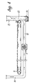
- the granular, together with the projectiles fired into the same, see figure 4, is caused to drop from said conveyor belt 3, 4 onto the conveyor belt 9 that conveys said granular material as well as said projectiles towards a separation zone 10.
- a blower 11 is provided upstream said zone and connected to the same through conduit 12, said blower causing the separation of the granular material from the projectiles by the action of the air delivered into said zone 10 through conduit 12.
- the granular material is delivered through conduit 13 above the heap 1 while the projectiles will drop by gravity into the collector 14.
- the air flow acting as a carrier for the granular material through conduit 13 is filtered in a suitable way, if necessary, and then sent again through conduit 15 to the blower 11, so that a closed cycle is realized that needs no restoring of the air.
- the granular material and projectiles fired drop on a sliding gate 16, and then into the conduit 17.
- a blower 18 is provided upstream said conduit 17, the blower acting so as to push the mixed mass of the granular material and the projectiles fired up to the zone 19 where the projectiles are collected by gravity into the box 20 whereas the granular material is pushed by the air flow through conduit 21 up to the top of the heap 1.
- the air is filtered once it has been separated from the granular material, and then it is sent again to blower 18 through conduit 15.
- Material to be tested 20 mm foam rubber in the form of bags of heavy polyethylene Arm : lightweight automatic rifle "F.A.L.”, 7.62 gauge NATO, with SMI 9.30 g projectile Firing distance: 40 m
- Direction of the projectiles at right angles to the material to be tested
- Position of the shooter on the ground in yard
- Results the first 5-6 projectiles were stopped after going through a thickness of about 1.30-1.50 m of the material with no appreciable deformation.
Landscapes
- Engineering & Computer Science (AREA)
- General Engineering & Computer Science (AREA)
- Combined Means For Separation Of Solids (AREA)
Claims (10)
- Auffangevorrichtung fuer Geschosse von leichten Waffen sowie Waffen anderer Art, insbesondere in bedeckten Schiessplaetzen oder Schiessgallerien, welche eine aus einer haufenfoermigen Anordnung von koernigen Materialen bestehende Anprallstruktur (1) fuer Geschosse und eine Rueckgewinnungs- und/oder Regenerationsanordnung fuer dieses koernige Material, mit Abscheidung von Geschossen enthaelt, wobei diese Rueckgewinnungs- und/oder Regenerationsanordnung fuer das koernige Material aus mindestens einem Trage- und Foedermittel (3,4) fuer das aus koernigem Material und Geschossen bestehende Gemisch und mechanischen Mitteln (11, 18) zur Rueckforderung des koernigen Materials zu Verteilungsmitteln (12,21) besteht, die dieses Material auf das Haufen bestreuen, dadurch dadurch gekennzeichnet, dass die genannten Trage- und Foerdermitteln (3,4) entsprechend dem Reibungswinkel der Materialmasse angeordnet sind, wodurch diese Materialmasse sich in Querrichtung zur Achse des Schiessplatzes verstellt.
- Auffangevorrichtung fuer Geschosse nach Anspruch 1, dadurch gekennzeichnet, dass die genannten Trage- und Foerdermittel (3,4) fuer das Material aus Rollgitter- oder Foerderbahnmitteln bestehen.
- Auffangevorrichtung fuer Geschosse nach Anspruch 1 oder 2, dadurch gekennzeichnet, dass weitere Mittel (9) zur Foerderung des koernigen Materials zu den Abscheidemitteln auch am unteren Teil der genannten Trage- und Foerdermittel (3,4) und stromabwaerts zu denselben angeordnet sind.
- Auffangevorrichtung fuer Geschosse nach Anspruch 3, dadurch gekennzeichnet, dass die genannten weiteren Foerdermittel (9) aus einem Metallband, Kunststoffband oder einem Mischstoff-Foerdeband oder auch aus anderen mechanischen Mittelen bestehen.
- Auffangevorrichtung fuer Geschosse nach Anspruch 3, dadurch gekennzeichnet, dass die genannten Abscheidemittel Zufuhrmittel enthalten, die in Leitungsmitteln (12) angeordnet sind und deren zugefuhrte Fluessigkeit, vorzugsweise Luft, auf das genannte, mit den Geschossen gemischte koernige Material einwirkt, das ummittelbar durch gie genannten Trage- und Foerdermittel (3,4) oder durch die genannten weiteren Foerdermittel (9) gefoerdert wird, so dass das genannte koernige Material durch die genannten Foerdermittel zum genannten Haufen rueckgefuehrt wird, waehrend die Geschosse durch Schwerkraft in einen Aufnahmebehaelter herunter fallen.
- Auffangevorrichtung fuer Geschosse nach Anspruch 5, dadurch gekennzeichnet, dass die als Abscheidemittel der Geschosse vom koernigen Material wirkende Fluessigkeit an die Zufuhrmitteln (11,18) durch weitere Leitungsmittel (15) zurueckgefuehrt wird, die die genannten Zufurhmitteln mit den Gipfel des genannten Haufens verbinden.
- Auffangevorrichtung fuer Geschosse nach Anspruch 5 oder 6, dadurch gekennzeichnet, dass die genannten Zufuhrmittel (11) aus einem Ejektor oder Geblaese bestehen.
- Auffangevorrichtung fuer Geschosse nach Anspruechen 5,6 oder 7, dadurch gekennzeichnet, dass an den genannten Abscheide- und Leitungsmitteln Automatisierungs- und Selbsteinstellungsmittel fuer das Ruecklaufverfahren vorgesehen sind.
- Auffangevorrichtung fuer Geschosse nach Anspruch 7, dadurch gekennzeichnet, dass stromauf zum genannten Leitungsmittel (15), die die Zufuhrmittel (11,18) mit dem Gipfel des Haufens verbinden, Filtermittel vorgesehen sind.
- Auffangevorrichtung fuer Geschosse nach Anspruch 1, dadurch gekennzeichnet, dass stromab zur genannten Rueckgewinnungs- und/oder Regenerationsanordnung fuer das genannte koernige Material und fuer die Abscheidung der Geschosse, ein Schmelztiegel fuer Blei, zu dem die genannten Geschosse automatisch zugefuehrt werden, und eine Mehrzahl von Block-Kokillen vorgesehen sind, in den das geschmolzene Blei zu Blocken erstarrt.
Priority Applications (1)
| Application Number | Priority Date | Filing Date | Title |
|---|---|---|---|
| AT85902630T ATE67029T1 (de) | 1984-06-01 | 1985-05-31 | Kugelfang mit einrichtungen zum regenerieren des geschossauffangenden materials. |
Applications Claiming Priority (4)
| Application Number | Priority Date | Filing Date | Title |
|---|---|---|---|
| IT4830884 | 1984-06-01 | ||
| IT48308/84A IT1178386B (it) | 1984-06-01 | 1984-06-01 | Fermapalle balistico, a struttura ad autorigenerazione, idoneo ai tiri con armi portatili e non, in particolare in poligoni in galleria |
| IT4752285 | 1985-01-04 | ||
| IT47522/85A IT1181837B (it) | 1985-01-04 | 1985-01-04 | Fermapalle balistico con sistema di rigenerazione e/o reimpiego del materiale di impatto |
Related Child Applications (1)
| Application Number | Title | Priority Date | Filing Date |
|---|---|---|---|
| EP90114579.7 Division-Into | 1990-07-30 |
Publications (2)
| Publication Number | Publication Date |
|---|---|
| EP0186682A1 EP0186682A1 (de) | 1986-07-09 |
| EP0186682B1 true EP0186682B1 (de) | 1991-09-04 |
Family
ID=26329198
Family Applications (1)
| Application Number | Title | Priority Date | Filing Date |
|---|---|---|---|
| EP85902630A Expired EP0186682B1 (de) | 1984-06-01 | 1985-05-31 | Kugelfang mit einrichtungen zum regenerieren des geschossauffangenden materials |
Country Status (6)
| Country | Link |
|---|---|
| US (1) | US4728109A (de) |
| EP (1) | EP0186682B1 (de) |
| AU (1) | AU4408485A (de) |
| DE (1) | DE3584008D1 (de) |
| EG (1) | EG16973A (de) |
| WO (1) | WO1985005672A1 (de) |
Families Citing this family (39)
| Publication number | Priority date | Publication date | Assignee | Title |
|---|---|---|---|---|
| ES2008683B3 (es) * | 1985-12-20 | 1989-08-01 | A B C Appalti Bonifiche E Costr Di Elio Floria & C S A S | Equipo con septo amortiguador de energia para balas, a instalar en campos de tiro. |
| IT1211950B (it) * | 1987-12-03 | 1989-11-08 | Icos Impresa Constr | In particolare tiri in galleria perfezionamento nei fermapalle balistici ad autorigenerazione idonei a tiri con armi portatili e simili, |
| IT1231788B (it) * | 1989-05-22 | 1992-01-14 | Icos Impresa Constr | Gruppo di convogliamento e separazione in fermapalle balistici |
| US5171020A (en) * | 1990-01-19 | 1992-12-15 | Wojcinski Allan S | Target backstop using granulated material |
| US5435571A (en) * | 1990-01-19 | 1995-07-25 | Caswell International Corporation | Granulate backstop assembly |
| US5607163A (en) * | 1990-01-19 | 1997-03-04 | Caswell International Corporation | Granulate backstop assembly |
| GB2242730A (en) * | 1990-04-07 | 1991-10-09 | John Alan Vertanness | Bullet trap |
| US5121671A (en) * | 1990-12-14 | 1992-06-16 | Passive Bullet Traps Limited | Bullet trap |
| WO1992010717A1 (en) * | 1990-12-14 | 1992-06-25 | Ronald Coburn | Bullet trap |
| US5113700A (en) * | 1990-12-14 | 1992-05-19 | Passive Bullet Traps Limited | Bullet trap |
| US5070763A (en) * | 1990-12-14 | 1991-12-10 | Passive Bullet Traps Limited | Bullet trap |
| US5848794A (en) | 1991-01-18 | 1998-12-15 | Caswell International Corporation | Granulate backstop assembly |
| US5255924A (en) * | 1992-02-03 | 1993-10-26 | Copius Craig C | Contaminant recovery system for a rifle range |
| GB2290370A (en) * | 1994-06-14 | 1995-12-20 | John Alan Vertanness | 'Encapsulator' dual-system bullet catcher for use in lead-free indoor ranges |
| US5669172A (en) * | 1995-09-20 | 1997-09-23 | Goral; Norbert | Gun safety device |
| SE505107C2 (sv) * | 1995-10-17 | 1997-06-23 | Gerth Moberg | Urlakningsskydd |
| US5686688A (en) * | 1996-02-20 | 1997-11-11 | Wright Malta Corporation | Noise abatement system for large caliber gun |
| US6173956B1 (en) | 1996-09-27 | 2001-01-16 | O.M.F. Inc. | Projectile backstop assembly |
| US5907930A (en) * | 1997-11-26 | 1999-06-01 | Ricco, Sr.; John A. | Shooting range |
| US5901960A (en) * | 1998-01-13 | 1999-05-11 | Caswell International Corporation | Granulate-backstop assembly |
| US6311980B1 (en) * | 1999-09-28 | 2001-11-06 | Action Target, Inc. | Projectile retrieval system |
| US7140615B1 (en) * | 1999-09-28 | 2006-11-28 | Action Target, Inc. | Projectile retrieval system |
| US6378870B1 (en) * | 1999-12-24 | 2002-04-30 | Action Target, Inc. | Apparatus and method for decelerating projectiles |
| US6533280B1 (en) | 2000-03-03 | 2003-03-18 | H. Addison Sovine | Bullet backstop assembly |
| US7775526B1 (en) | 2001-12-12 | 2010-08-17 | Action Target Inc. | Bullet trap |
| US7194944B2 (en) * | 2001-12-12 | 2007-03-27 | Action Target, Inc. | Bullet trap |
| US7621209B2 (en) * | 2002-07-12 | 2009-11-24 | Action Target Acquisition Crop. | Modular ballistic wall |
| US20050034594A1 (en) * | 2002-09-17 | 2005-02-17 | Parks Jimmy A. | Projectile retrieval system |
| US7354044B2 (en) * | 2002-12-02 | 2008-04-08 | The United States Of America As Represented By The Secretary Of The Navy | Partitioned particulate bullet trap |
| US6715761B1 (en) | 2003-03-14 | 2004-04-06 | Gerth Moberg | Apparatus for shooting ranges |
| US7163205B1 (en) * | 2003-09-23 | 2007-01-16 | The United States Of America As Represented By The Secretary Of The Army | Recovery apparatus for fragmented ballistic materials and method for collection of the same |
| US20060107985A1 (en) * | 2004-04-13 | 2006-05-25 | Sovine H A | Modular shoot house facility |
| US8469364B2 (en) | 2006-05-08 | 2013-06-25 | Action Target Inc. | Movable bullet trap |
| US20110233869A1 (en) * | 2010-03-25 | 2011-09-29 | John Ernest M | Ballistic paneling for bullet traps |
| US8827273B2 (en) | 2010-08-02 | 2014-09-09 | Action Target Inc. | Clearing trap |
| SE536516C2 (sv) * | 2012-06-04 | 2014-01-21 | Stapp Internat Ab | Urlakningsskydd för skjutbanor utomhus |
| US9132453B1 (en) | 2014-03-01 | 2015-09-15 | Gregg L. Bouslog | Systems and methods for separating metal from rubber |
| US10371489B2 (en) | 2016-01-15 | 2019-08-06 | Action Target Inc. | Bullet deceleration tray damping mechanism |
| CA3225134A1 (en) * | 2021-07-09 | 2023-01-12 | Dustin SIKORA | Systems and methods for separating bullets from backstop material |
Family Cites Families (8)
| Publication number | Priority date | Publication date | Assignee | Title |
|---|---|---|---|---|
| US1728046A (en) * | 1927-07-21 | 1929-09-10 | Cabot Co | Apparatus for separation of solids |
| US2411026A (en) * | 1944-02-21 | 1946-11-12 | Douglas Aircraft Co Inc | Firing range butt |
| US2631454A (en) * | 1950-06-30 | 1953-03-17 | Berger M Shepard | Water gun butt and apparatus |
| US2850162A (en) * | 1954-08-11 | 1958-09-02 | Buehler Ag Geb | Separators for pneumatically conveyed aggregate goods |
| US3572503A (en) * | 1968-11-04 | 1971-03-30 | Waste Reclamation Corp | Trash segregation apparatus |
| US3920542A (en) * | 1974-06-04 | 1975-11-18 | Us Agriculture | Removal of green bolls and heavy materials from seed cotton by air jets |
| JPS5813724A (ja) * | 1980-12-05 | 1983-01-26 | ツリユツラ−・ゲゼルシヤフト・ミツト・ベシユレンクテル・ハフツング・ウント・コンパニ−・コマンデイトゲゼルシヤフト | 繊維材料から異物及び高比重分を除去する方法及び装置 |
| DE3212781A1 (de) * | 1982-04-06 | 1983-10-06 | Gfl Sportstaettenbau Gmbh | Kugelfang, insbesondere fuer solche schiessanlagen, die in geschlossenen raeumen angelegt sind |
-
1985
- 1985-05-30 EG EG33485A patent/EG16973A/xx active
- 1985-05-31 AU AU44084/85A patent/AU4408485A/en not_active Abandoned
- 1985-05-31 DE DE8585902630T patent/DE3584008D1/de not_active Expired - Fee Related
- 1985-05-31 EP EP85902630A patent/EP0186682B1/de not_active Expired
- 1985-05-31 US US06/845,275 patent/US4728109A/en not_active Expired - Fee Related
- 1985-05-31 WO PCT/IT1985/000004 patent/WO1985005672A1/en not_active Ceased
Also Published As
| Publication number | Publication date |
|---|---|
| AU4408485A (en) | 1985-12-31 |
| US4728109A (en) | 1988-03-01 |
| DE3584008D1 (de) | 1991-10-10 |
| WO1985005672A1 (en) | 1985-12-19 |
| EP0186682A1 (de) | 1986-07-09 |
| EG16973A (en) | 1993-12-30 |
Similar Documents
| Publication | Publication Date | Title |
|---|---|---|
| US4728109A (en) | Ballistic projectile-arrester, having a regeneration and/or recovery system for the impact material | |
| US4786059A (en) | Equipment with energy knocking-down septum for bullets, to be installed in shooting ranges | |
| US6173956B1 (en) | Projectile backstop assembly | |
| EP0323410B1 (de) | Autoregenerierender Geschossfänger für Kleinschusswaffen, insbesondere für Innenschiessstände | |
| US2411026A (en) | Firing range butt | |
| US5718434A (en) | Bullet trap | |
| US5085765A (en) | Conveying and separation unit for ballistic projectile arresters | |
| CN105855040B (zh) | 一种斜式分级磁选装置 | |
| KR102022827B1 (ko) | 도탄 방지용 피탄패널을 이용한 경사형 탄두수거장치 | |
| EP0405616A2 (de) | Geschossfangvorrichtung mit einem Rücklauf- und Wiedergewinnungssystem für das geschossbremsende Material | |
| DE974292C (de) | Wanderrostfeuerung mit einem Flugaschenrueckfuehrer | |
| JPH0520680B2 (de) | ||
| US7354044B2 (en) | Partitioned particulate bullet trap | |
| AU645163B2 (en) | Bullet trap | |
| DE186682T1 (de) | Kugelfang mit einrichtungen zum regenerieren des geschossauffangenden materials. | |
| CN2499370Y (zh) | 小直径易拆装可限速连体双螺旋输放装置 | |
| KR101492715B1 (ko) | 실거리사격장용 탄두 회수 장치 | |
| Hartmann et al. | Rock Dusting and Sampling Including Wet Rock Dusting at the Bureau of Mines Experimental Coal Mine | |
| Hartmann et al. | Report of Investigations 5264: Coal-Mine-Explosion Research by the Bureau of Mines, 1954-55 | |
| GB2290370A (en) | 'Encapsulator' dual-system bullet catcher for use in lead-free indoor ranges | |
| SU818995A1 (ru) | Амортизирующий полочный спуск | |
| Hartmann et al. | Coal-mine-explosion Research by the Bureau of Mines, 1954-55 | |
| DE2320851A1 (de) | Anlage zum bergen und zufuehren kuenstlicher ziele fuer ein neues schiesspiel | |
| JPS5895009A (ja) | 落下衝撃緩和装置 | |
| DE202022103144U1 (de) | Geschossfang mit modularen Prallplatten |
Legal Events
| Date | Code | Title | Description |
|---|---|---|---|
| PUAI | Public reference made under article 153(3) epc to a published international application that has entered the european phase |
Free format text: ORIGINAL CODE: 0009012 |
|
| 17P | Request for examination filed |
Effective date: 19860212 |
|
| AK | Designated contracting states |
Kind code of ref document: A1 Designated state(s): AT BE CH DE FR GB IT LI LU NL SE |
|
| ITCL | It: translation for ep claims filed |
Representative=s name: BARZANO' E ZANARDO ROMA S.P.A. |
|
| TCAT | At: translation of patent claims filed | ||
| TCNL | Nl: translation of patent claims filed | ||
| EL | Fr: translation of claims filed | ||
| DET | De: translation of patent claims | ||
| 17Q | First examination report despatched |
Effective date: 19870318 |
|
| RAP3 | Party data changed (applicant data changed or rights of an application transferred) |
Owner name: IMPRESA COSTRUZIONI SOC. FRA.SA A R.L. |
|
| GRAA | (expected) grant |
Free format text: ORIGINAL CODE: 0009210 |
|
| AK | Designated contracting states |
Kind code of ref document: B1 Designated state(s): AT BE CH DE FR GB IT LI LU NL SE |
|
| REF | Corresponds to: |
Ref document number: 67029 Country of ref document: AT Date of ref document: 19910915 Kind code of ref document: T |
|
| XX | Miscellaneous (additional remarks) |
Free format text: TEILANMELDUNG 90114579.7 EINGEREICHT AM 31/05/85. |
|
| ITF | It: translation for a ep patent filed | ||
| REF | Corresponds to: |
Ref document number: 3584008 Country of ref document: DE Date of ref document: 19911010 |
|
| REG | Reference to a national code |
Ref country code: CH Ref legal event code: PL |
|
| ET | Fr: translation filed | ||
| PGFP | Annual fee paid to national office [announced via postgrant information from national office to epo] |
Ref country code: FR Payment date: 19920515 Year of fee payment: 8 |
|
| PGFP | Annual fee paid to national office [announced via postgrant information from national office to epo] |
Ref country code: SE Payment date: 19920519 Year of fee payment: 8 Ref country code: GB Payment date: 19920519 Year of fee payment: 8 |
|
| PGFP | Annual fee paid to national office [announced via postgrant information from national office to epo] |
Ref country code: LU Payment date: 19920520 Year of fee payment: 8 Ref country code: BE Payment date: 19920520 Year of fee payment: 8 |
|
| PGFP | Annual fee paid to national office [announced via postgrant information from national office to epo] |
Ref country code: AT Payment date: 19920527 Year of fee payment: 8 |
|
| PGFP | Annual fee paid to national office [announced via postgrant information from national office to epo] |
Ref country code: NL Payment date: 19920531 Year of fee payment: 8 |
|
| PGFP | Annual fee paid to national office [announced via postgrant information from national office to epo] |
Ref country code: CH Payment date: 19920605 Year of fee payment: 8 |
|
| REG | Reference to a national code |
Ref country code: CH Ref legal event code: AEN |
|
| PLBE | No opposition filed within time limit |
Free format text: ORIGINAL CODE: 0009261 |
|
| STAA | Information on the status of an ep patent application or granted ep patent |
Free format text: STATUS: NO OPPOSITION FILED WITHIN TIME LIMIT |
|
| PGFP | Annual fee paid to national office [announced via postgrant information from national office to epo] |
Ref country code: DE Payment date: 19920730 Year of fee payment: 8 |
|
| 26N | No opposition filed | ||
| EPTA | Lu: last paid annual fee | ||
| PG25 | Lapsed in a contracting state [announced via postgrant information from national office to epo] |
Ref country code: LU Free format text: LAPSE BECAUSE OF NON-PAYMENT OF DUE FEES Effective date: 19930531 Ref country code: LI Effective date: 19930531 Ref country code: GB Effective date: 19930531 Ref country code: CH Effective date: 19930531 Ref country code: BE Effective date: 19930531 Ref country code: AT Effective date: 19930531 |
|
| PG25 | Lapsed in a contracting state [announced via postgrant information from national office to epo] |
Ref country code: SE Effective date: 19930601 |
|
| BERE | Be: lapsed |
Owner name: IMPRESA COSTRUZIONI SOC. FRA.SA A R.L. Effective date: 19930531 |
|
| PG25 | Lapsed in a contracting state [announced via postgrant information from national office to epo] |
Ref country code: NL Effective date: 19931201 |
|
| NLV4 | Nl: lapsed or anulled due to non-payment of the annual fee | ||
| GBPC | Gb: european patent ceased through non-payment of renewal fee |
Effective date: 19930531 |
|
| PG25 | Lapsed in a contracting state [announced via postgrant information from national office to epo] |
Ref country code: FR Effective date: 19940131 |
|
| REG | Reference to a national code |
Ref country code: CH Ref legal event code: PL |
|
| PG25 | Lapsed in a contracting state [announced via postgrant information from national office to epo] |
Ref country code: DE Effective date: 19940201 |
|
| REG | Reference to a national code |
Ref country code: FR Ref legal event code: ST |
|
| EUG | Se: european patent has lapsed |
Ref document number: 85902630.4 Effective date: 19940110 |