EP0186730B1 - Verfahren zum Ausrichten eines Reinraumstromes und Reinraumerzeuger - Google Patents
Verfahren zum Ausrichten eines Reinraumstromes und Reinraumerzeuger Download PDFInfo
- Publication number
- EP0186730B1 EP0186730B1 EP85110123A EP85110123A EP0186730B1 EP 0186730 B1 EP0186730 B1 EP 0186730B1 EP 85110123 A EP85110123 A EP 85110123A EP 85110123 A EP85110123 A EP 85110123A EP 0186730 B1 EP0186730 B1 EP 0186730B1
- Authority
- EP
- European Patent Office
- Prior art keywords
- clean
- space
- air
- stream
- clean room
- Prior art date
- Legal status (The legal status is an assumption and is not a legal conclusion. Google has not performed a legal analysis and makes no representation as to the accuracy of the status listed.)
- Expired - Lifetime
Links
- 238000000034 method Methods 0.000 title claims description 14
- 230000001954 sterilising effect Effects 0.000 claims abstract description 6
- 238000004659 sterilization and disinfection Methods 0.000 claims abstract description 5
- 239000003570 air Substances 0.000 claims description 181
- 239000012080 ambient air Substances 0.000 claims description 11
- XLYOFNOQVPJJNP-UHFFFAOYSA-N water Substances O XLYOFNOQVPJJNP-UHFFFAOYSA-N 0.000 claims description 11
- 239000007788 liquid Substances 0.000 claims description 7
- 230000006641 stabilisation Effects 0.000 claims description 7
- 238000011105 stabilization Methods 0.000 claims description 7
- 239000000645 desinfectant Substances 0.000 claims description 2
- 238000001704 evaporation Methods 0.000 claims description 2
- 230000008020 evaporation Effects 0.000 claims description 2
- 239000002184 metal Substances 0.000 claims description 2
- 229910052751 metal Inorganic materials 0.000 claims description 2
- 230000001105 regulatory effect Effects 0.000 claims 1
- 238000011144 upstream manufacturing Methods 0.000 claims 1
- 238000001816 cooling Methods 0.000 abstract description 16
- 238000010438 heat treatment Methods 0.000 abstract description 3
- 230000008878 coupling Effects 0.000 description 13
- 238000010168 coupling process Methods 0.000 description 13
- 238000005859 coupling reaction Methods 0.000 description 13
- 238000001035 drying Methods 0.000 description 7
- 208000002847 Surgical Wound Diseases 0.000 description 5
- 244000052616 bacterial pathogen Species 0.000 description 5
- 238000004519 manufacturing process Methods 0.000 description 4
- 206010052428 Wound Diseases 0.000 description 3
- 208000027418 Wounds and injury Diseases 0.000 description 3
- 230000015572 biosynthetic process Effects 0.000 description 3
- 229910052802 copper Inorganic materials 0.000 description 2
- 239000010949 copper Substances 0.000 description 2
- 230000002349 favourable effect Effects 0.000 description 2
- 239000002245 particle Substances 0.000 description 2
- 239000002904 solvent Substances 0.000 description 2
- 238000009423 ventilation Methods 0.000 description 2
- RYGMFSIKBFXOCR-UHFFFAOYSA-N Copper Chemical compound [Cu] RYGMFSIKBFXOCR-UHFFFAOYSA-N 0.000 description 1
- 238000010521 absorption reaction Methods 0.000 description 1
- 239000000443 aerosol Substances 0.000 description 1
- 238000004378 air conditioning Methods 0.000 description 1
- 230000001143 conditioned effect Effects 0.000 description 1
- 239000000356 contaminant Substances 0.000 description 1
- 238000011109 contamination Methods 0.000 description 1
- 150000001879 copper Chemical class 0.000 description 1
- 230000001419 dependent effect Effects 0.000 description 1
- 238000010586 diagram Methods 0.000 description 1
- 238000010790 dilution Methods 0.000 description 1
- 239000012895 dilution Substances 0.000 description 1
- 230000000694 effects Effects 0.000 description 1
- 208000015181 infectious disease Diseases 0.000 description 1
- 239000000203 mixture Substances 0.000 description 1
- 239000003507 refrigerant Substances 0.000 description 1
Images


Classifications
-
- A—HUMAN NECESSITIES
- A61—MEDICAL OR VETERINARY SCIENCE; HYGIENE
- A61G—TRANSPORT, PERSONAL CONVEYANCES, OR ACCOMMODATION SPECIALLY ADAPTED FOR PATIENTS OR DISABLED PERSONS; OPERATING TABLES OR CHAIRS; CHAIRS FOR DENTISTRY; FUNERAL DEVICES
- A61G13/00—Operating tables; Auxiliary appliances therefor
- A61G13/10—Parts, details or accessories
- A61G13/108—Means providing sterile air at a surgical operation table or area
-
- F—MECHANICAL ENGINEERING; LIGHTING; HEATING; WEAPONS; BLASTING
- F24—HEATING; RANGES; VENTILATING
- F24F—AIR-CONDITIONING; AIR-HUMIDIFICATION; VENTILATION; USE OF AIR CURRENTS FOR SCREENING
- F24F9/00—Use of air currents for screening, e.g. air curtains
Definitions
- the invention relates to a method for clean room production by means of a clean room flow which, by supplying clean room supply air formed by disinfection and optionally humidification of supply air in a clean room generator, generates through at least one air outlet opening of this clean room generator and is oriented towards an operating field in such a way that it envelops it tangentially .
- the invention relates to a clean room generator with at least one clean air generator for the production of germ-free and possibly humidified clean room supply air from supply air sucked into the supply air, and with a fan head connected thereto, into which the clean room supply air is introduced and from its air outlet opening (s) as Clean room flow is aligned or aligned with a clean room area such that it is tangentially enveloped by the clean room flow.
- supply air is generally the air flow within the clean room generator, whereby clean room supply air is to be understood as the supply air which has already been sterilized, and the cleanroom stream is the envelope stream emerging from the cleanroom generator and made of sterilized air.
- a method of the type mentioned above is e.g. described in DE-A 24 39 778, which relates to an arrangement for air conditioning and keeping the air sterile in an operating room, in particular in the area of the operating field, by displacing the room air by means of conditioned, sterile supply air.
- the clean room generation has been limited to a restricted protection zone within the operating room, in such a way that sterile air in the immediate vicinity of the operating field with the formation of a germ-free one Air curtain is fed.
- This air curtain should either consist of a clean room flow guided tangentially over the operation site or of a clean room flow radially acting on the operation site from an annular source surrounding it. Accordingly, the normal direction of the passage for the clean room supply air should run approximately tangentially to the surgical site or enclose the surgical site in a ring.
- At least two streams of bacteria-free air should be directed and crossed with one another in such a way that the area to be kept clean is delimited from the crossed streams Angular range is in which eddy current formation is to be brought about, so that the clean air flows through the area to be kept clean as a vortex flow.
- This vortex flow prevents the settling of particles, but at the risk of drying out the surgical wound.
- the supply of air is provided with a temperature which is generally different from the ambient temperature.
- the known selectability of the temperature of the clean room air cannot achieve a reduction in the air delivery capacity required for satisfactory germ-free keeping, and a task directed to this is not even addressed in DE-A 32 08 123.
- the clean room flow is bundled by thermal stabilization, in that it is brought to and maintained at a temperature which is clearly, but slightly below, the ambient temperature in the clean room area.
- This thermal stabilization clearly distinguishes the clean room flow from the ambient air surrounding it by forming a very exact boundary layer with the ambient air, which is not exceeded even by those filaments that form at the boundary with the ambient air within the clean room flow.
- the individual flow threads are kept close together in the clean room flow, so that even at a great distance from their air outlet opening they still form an exactly formed clean room flow. This is so dense that no germs can get through it into the clean room. In this way, the flow losses can be kept small.
- the clean room flow can therefore be generated with a relatively small amount of air, for which a moderate fan output is sufficient. It is also achieved that the clean room flow maintains its bundling behind the air outlet opening in the area of the clean room even if the latter is a considerable distance behind the air outlet opening in the direction of flow. Distances such as those specified in an operating field by the length of a human body can be covered well with a precisely bundled clean room flow. Since it is sufficient for the bundling of the clean room flow through thermal stabilization if the temperature is slightly below that of the surroundings, a very effective bundling of the clean room flow can be achieved with technically simple, inexpensive means. In addition, the heat dissipated from the supply air for the clean room flow can possibly be used for other purposes.
- the tangential clean room flow bundled by thermal stabilization can be directed by a preferably likewise thermally stabilized secondary clean room flow.
- This secondary clean room flow meets the tangential clean room flow at a predetermined angle and directs it in a direction suitable for the respective application. In this way it can be achieved that the tangential clean room flow in any case flows tangentially around the clean room to be shielded, so that it can be encased very close to the clean room flow without any drying out of surgical or burn wounds having to be expected.
- the tangential clean room flow can be directed in any direction by appropriate alignment of the secondary clean room flow.
- the secondary clean room flow can be directed vertically upward from the operating table.
- the degree of deflection of the clean room flow depends not only on the direction but also on the strength of the secondary clean room flow.
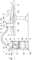
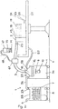
- a clean room generator essentially consists of a clean air generator 1 and a fan head 2, which is connected to the clean air generator 1 via at least one flexible hose 3.
- the fan head 2 rises above an operating table 21. It can be movably connected to it. With regard to a plane spanned by the operating table 21, the fan head 2 can be fastened in a pivotable manner as well as displaceable in the direction of the operating table 21. In addition, it is conceivable to attach the fan head 2 to a holder that is independent of the operating table 21, so that it can be adjusted with respect to the surface of the operating table 21 in such a way that an operating field 20 is flowed tangentially by a clean room flow 19 flowing out of the fan head 2.
- This operating field 20 can be provided at a selected location on a human body, which lies on the operating table 21 as a patient 22. Due to the tangential flow to the operating field 20, this is screened from the clean room flow 19 flowing out of the fan head 2 against the ambient air without germs, without the operating field 20 being included in the clean room flow 19 and thus being at risk of drying out under the influence of the air flow 19.
- the clean air generator 1 is set up in the vicinity of the operating table 21, so that the flexible hose 3 can be chosen to be relatively short.
- the hood of the flexible hose 3 favors its disinfection, for example in an autoclave, not shown.
- the flexible hose 3 must be selected at least so long that its length is sufficient to be able to connect the fan head 2 to the clean air generator 1 even when the fan head 2 is on a location of the operating table 21 is required, which is relatively far from the respective location of the clean air generator 1.
- the clean air generator 1 is mounted on wheels 35 with which it is supported on a floor 4. These wheels 35 allow the clean air generator 1 to be moved into a position favorable to the respective operating field 20.
- the wheels 35 are fastened to a housing 36 in which a conveyor 9 is elastically mounted with its drive 10.
- a heat exchanger 7 below the conveyor 9, below which an air inlet opening 6 opens into an air distributor 37.
- This air distributor 37 distributes the air sucked in by the conveyor 9 through the air inlet opening 6 as supply air for the clean air generation uniformly via a heat transfer surface provided by the heat exchanger 7 for cooling the air.
- the air inlet opening 6 is expediently provided on an upper end 5 of the clean air generator 1 opposite the wheels 35. In this way, the conveyor 9 draws a relatively clean air from its surroundings. If necessary, the air inlet opening 6 can be connected via a connecting hose 38 to a fresh air atmosphere prevailing outside an operating room.
- the conveyor 9 presses the fresh air drawn in by it and cooled in the heat exchanger 7 in the direction of the flexible hose 3, which can be connected to an air outlet opening 11 of the housing 36 via a coupling 14.
- This air outlet opening 11 can be provided on an upper end 13 of the housing 36 opposite the wheels 35.
- Filter 12 is fitted into the housing 36 between the air outlet opening 11 and the conveyor 9.
- the air conveyed by the conveyor 9 in the direction of the air outlet opening 11 passes through the filter 12 on its way to the air outlet opening 11 and is both sterilized in this and also cleaned of other contaminants and thus converted into clean air.
- a filter 12 other devices for sterilizing the fresh air and thus for the formation of clean air can also be provided.
- the flexible hose 3 is connected with its end facing away from the clean air generator 1 to the fan head 2 via a coupling 16. With the aid of this coupling 16, an end 15 of the flexible hose 3 facing away from the clean air generator 1 can be connected to an air inlet 17 attached to the fan head 2 for the introduction of clean air into the fan head 2.
- This air inlet 17 can for example be attached to a rear end face 39 of the fan head 2, which delimits the fan head 2 on a side opposite a front end face 40.
- the front end face 40 and the rear end face 39 span planes which can run plane-parallel to one another.
- the clean room flow 19 flowing tangentially to the operating field 20 emerges from the front end face 40.
- the air inlet 17 is provided at any other point on the fan head 2, as long as it is suitable for evenly distributing the clean air supply air flow generated by the clean air generator 1 over an air outlet opening 18 which is in the front end face 40 is arranged congenitally.
- the air outlet opening 18 can also be divided into a plurality of small openings 41 which are arranged in the front end face 40.
- Controllable internals 42 can be provided in the air outlet opening 18, with the aid of which the direction and strength of the clean room flow 19 can be controlled. These controllable internals 42 can be steering flaps, blinds and other internals which are suitable for directing or preventing the clean room flow 19.
- the arched design of the air outlet opening corresponds to the shape of the fan head 2, which can be in the form of a horseshoe.
- This horseshoe projects with its two legs 43, 44 in the direction of the operating table 21.
- the two legs 43, 44 are connected to one another by a yoke 45.
- the length of this yoke 45 is such that a passage 46 is spanned by it and the two legs 43, 44, which passage is wide enough to span the body of a patient 22 lying on the operating table 21.
- the front end face 40 of the fan head 2 expediently consists of a sintered metal which has very good aseptic properties.
- a cover 47 can protrude over the front end face 40 and protrudes over the front end face 40 in the form of a canopy.
- This diaphragm 47 extends at an upper end of the yoke 45 opposite the operating table 21 and projects with its opposite ends 48, 49 into an upper region of the legs 43, 44 which merges into the yoke 45.
- An air-guiding opening 50 is arranged between the cover 47 and the front end face 40 (FIG.
- Further air guiding openings 53 can be provided along the operating table 21 according to FIGS. 2 and 3. Secondary clean room flows 54 flow out of them and serve to deflect clean room flow 19 at a location suitable for the respective operating field 20.
- the clean room stream 19 For the purpose of bundling the clean room stream 19, it is thermally stabilized. This thermal stabilization is carried out in such a way that the clean room stream 19 is slightly cooled compared to its ambient air. Depending on the temperature of the ambient air and the necessities that result from the operation to be carried out, the air flow generated by the conveyor 9 is cooled in the heat exchanger 7 or warmed up somewhat in the bed stall. In the case of cooling, the heat exchanger 7 can be coupled to a cooling unit 8, so that a refrigerant biased in the cooling unit 8 expands in the heat exchanger 7. The cold released in the process draws the heat from the supply air flow passing through the heat exchanger 7. As a rule, cooling by a few central degrees is sufficient compared to the ambient air.
- This assembly 55 is connected via a flexible hose 56 to the housing 36 of the clean air generator 1, in which the conveyor 9 and the filter 12 are arranged.
- the flexible hose 56 is connected via couplings 23 to the housing 36 on the one hand and the structural unit 55 on the other hand.
- the conveyor 9 sucks in a supply air flow through an air inlet opening 6 provided on the unit 55, through the heat exchanger 7 provided in the unit 55 and presses the supply air flow through the flexible hose 3 into the fan head
- the clean room flow 10 leaves the latter in the direction of the operating field 20.
- the direction of the clean room flow 19 can be influenced by the secondary clean room flow 54 (FIG. 2).
- the supply air for this is drawn off in the area of the upper closure 18 via a secondary air hose 57 and directed in the direction of the operating table 21.
- a further secondary air outlet 58 is provided in the area of the upper end 18 over the pleasure outlet opening 11 provided for the supply air for the clean room flow 19 and is connected to the operating table 21 via the secondary air hose 57.
- Secondary air ducts 59 which are provided with controllable air guiding openings 53, run on the operating table 21. Depending on the opening of these air guiding openings 53, the secondary air flow 54 is directed in a direction toward the air flow 19 at a location suitable for the position of the respective operating field 20.
- the secondary clean room stream 54 contains a conveyor 61 and is connected to the air guide openings 53 via a hose 62.
- a secondary clean room generator 60 (FIG. 3).
- This contains a conveyor 61 and is connected to the air guide openings 53 via a hose 62.
- the secondary clean room stream 54 can be thermally stabilized with respect to the clean room flow 19 by means of a heat exchanger 63.
- the secondary clean room stream 54 also serves to bundle the clean room stream 19.
- the secondary clean room stream 54 passed through a filter 12 or 12 a also strengthens the clean room stream 19 in the region of its outer boundary and thus contributes to further shielding the operating field 20.
- a heat exchanger surface 65 is provided in the fan head 2, which can consist, for example, of a copper tube.
- This copper tube can be connected to a water source 65, the water of which flows around the heat transfer surface 64 on one side and flows off via a drain 66.
- the heat absorbed by the water can be obtained in a corresponding system.
- the heat transfer surface 64 in the form of a spiral tube in the clean room supply air flow.
- connection between the clean air generator 1, the cooling unit 8 and the fan head 2 are each provided with couplings 23, which can be designed as double lock couplings. These double lock couplings are used to keep the inside of both the tubes 3, 57 and the clean air generator 1 free of germs when the couplings 14, 16, 23 are released.
- These couplings 14, 16, 23 can be designed as a bayonet coupling. This can have, for example, an attachment piece 27 which is sealingly attached to the ends of the hose 3 and which can be sealingly engaged with a fitting piece 28 at its end facing away from the hose 3.
- This adapter 28 is attached to the clean air generator 1, the cooling unit 8 or the fan head.
- the extension 27 can be close to the fitting 28th end facing a turntable 29 radially surrounding the end piece 27, which carries a driver 30.
- the driver 30 can be sealingly guided into the interior 31 of the extension 27 facing the air flow and projects beyond the end of the extension 27 facing the adapter 28.
- the locking plate 32 of the adapter 28 has a pin 34, which is acted upon by the driver 30 when the clutch is closed when it is moved by the turntable 29 in the direction of the pin 34.
- the closing plate 32 of the fitting piece 28 is moved into an open position and thereby takes the closing plate 32 of the fitting piece 28 which is mounted adjacent to it.
- the two closing plates 32 are preferably arranged closely adjacent to one another and provided with a seal so that possible contamination of the closing plate 32 cannot get into the incoming air flow before the couplings 13, 15, 23 are attached.
- the filter 12 can be arranged in the direction of flow from the conveyor 9 or in front of the heat exchanger 7.
- the conveyor 9 can also be arranged in the flow direction in front of the heat exchanger 7 or behind the filter 12.
- the clean air generator 1 can also be designed so that it emits air currents of different temperatures.
- the clean air generator 1 is connected to separate air ducts of the fan head 2 via at least two different flexible hoses 3. These air guides (not shown) lead supply air flows of different temperatures to the air outlet openings 18.
- the clean room flow components 19 emerge from these as parallel partial clean room flows of different temperatures and are directed tangentially to the operating field 20. In this way it is possible to keep the hands of the operating personnel at a level which they find pleasant, even if the operation takes a relatively long time.
- the temperature required for the supply air flow is first generated in the heat exchanger 7.
- either the heat exchanger 7 is flowed through by an appropriately tempered medium.
- the supply air flow is generated, which is cleaned in the filter 12 in such a way that the clean room flow 19 coming from it cannot produce infections which jeopardize the success of an operation.
- This both cleaned and thermized clean room supply air flow is passed through the hose 3 into the fan head 2 and third of this through the air outlet openings 18 as tangentially directed to the respective operating field 20, he clean room 19.
- the fan head 2 can be brought into a position that is favorable for the respective operating field 20.
- the thermization of the clean room flow 19 causes it to surround the operating field 20 in a bundled manner.
- the clean room flow 19 can be directed by the controllable internals 42 in such a way that it has the correct tangential direction and the strength deemed necessary by the operating personnel in the area of the operating field.
- the secondary clean room stream 52, 54 (FIGS. 2, 3, 5, 7) can be switched on accordingly. This exits from air guide openings 50, 53 at the respectively desired point at which the clean room flow 19 is to be directed. It is conceivable to generate the supply air for the secondary clean room flow 52, 54 in the secondary air generator 60 and to heat it in relation to the clean room flow 19 in order to bundle the secondary clean room flows with respect to the clean room flow 19.
- the bundling of the clean room stream 19 by thermal stabilization can additionally be improved by moistening it.
- the moistening has the additional advantage that the surgical wound is prevented from drying out even if part of the surgical wound lies within the clean room flow 19 due to incorrect alignment of the air outlet openings 18.
- This humidification can be carried out with the help of a steam component within the supply air flow.
- the clean room supply air flow absorbs this steam component when it passes through a steam chamber 67, for example, which can be arranged in the course of the flexible hose 3.
- This steam chamber 67 is connected to a steam generator 69 via a connecting hose 68.
- this steam generator 69 there is a liquid to be evaporated, a liquid 70 to be evaporated, which is heated by a heat source, for example a gas heater 71.
- the liquid 70 heated by the gas heater 71 evaporates and passes from the steam generator 69 via the connecting hose 68 into the steam chamber 67; the clean room supply air flow passing through the steam chamber 67 from the clean air generator 1 in the direction of the fan head 2 is enriched with the steam in the steam chamber 67.
- This is aseptic since the liquid 70 is aseptic.
- the evaporation of the liquid 70 has a sterilizing effect.
- the steam particles are finely distributed in the supply air flow entering the fan head 2, so that they also inside the fan head 2 and do not condense when exiting the air outlet openings 18. Rather, they get into the area of the operating field 20 with the clean room flow 19 and prevent absorption of liquid from the area of the operating area 20 there existing moisture within the operating field 20 act.
- the dilution effect occurring in the area of the operating field 20 due to the clean room flow 19 can contribute significantly to the fact that germs originally present in the area of the surgical wound are also removed by the clean room flow 19. For this reason, the clean room flow 19 is aligned so that it can remove the germs located in the area of the operating field 20.
- the humidification of the supply air flow can also be brought about by passing it over a water bath. Finally, it is also conceivable to pass the supply air flow through a water bath. It is conceivable to set the temperature of the water bath so that the clean room stream 19 reaches the temperature below its ambient temperature necessary for its thermization.
- the steam chamber 67 or the water bath necessary for humidifying the supply air flow can be provided at any point of air ducts through which the supply air flow is directed, depending on the structural conditions of the system. For example, it is conceivable to provide the humidifier between the fan head 2 and the clean air generator 1. However, it is also possible to arrange a steam chamber 67 designed as a humidifier or a corresponding water bath between the conveyor 9 and the air outlet opening 11. Finally, it is conceivable to provide the humidifier in the fan head 2. It can also be arranged directly in front of the fan head 2.
- the humidifier can be designed as a solvent bath. In particular, it can be considered to use the solvent bath to create a disinfectant atmosphere within the supply air flow.
- An aerosol atmosphere is particularly suitable for this.
Landscapes
- Health & Medical Sciences (AREA)
- Engineering & Computer Science (AREA)
- Life Sciences & Earth Sciences (AREA)
- Animal Behavior & Ethology (AREA)
- General Engineering & Computer Science (AREA)
- Combustion & Propulsion (AREA)
- Surgery (AREA)
- Biomedical Technology (AREA)
- Chemical & Material Sciences (AREA)
- Mechanical Engineering (AREA)
- General Health & Medical Sciences (AREA)
- Public Health (AREA)
- Veterinary Medicine (AREA)
- Accommodation For Nursing Or Treatment Tables (AREA)
- Percussion Or Vibration Massage (AREA)
- Ventilation (AREA)
- Separation By Low-Temperature Treatments (AREA)
Priority Applications (1)
| Application Number | Priority Date | Filing Date | Title |
|---|---|---|---|
| AT85110123T ATE53290T1 (de) | 1984-08-16 | 1985-08-13 | Verfahren zum ausrichten eines reinraumstromes und reinraumerzeuger. |
Applications Claiming Priority (2)
| Application Number | Priority Date | Filing Date | Title |
|---|---|---|---|
| DE3430089A DE3430089C2 (de) | 1984-08-16 | 1984-08-16 | Verfahren zur Abgrenzung eines keimfrei zu haltenden Raumbereiches, insbesondere eines Operationsfeldes und Vorrichtung zur Durchführung des Verfahrens |
| DE3430089 | 1984-08-16 |
Publications (3)
| Publication Number | Publication Date |
|---|---|
| EP0186730A2 EP0186730A2 (de) | 1986-07-09 |
| EP0186730A3 EP0186730A3 (en) | 1987-09-30 |
| EP0186730B1 true EP0186730B1 (de) | 1990-06-06 |
Family
ID=6243154
Family Applications (1)
| Application Number | Title | Priority Date | Filing Date |
|---|---|---|---|
| EP85110123A Expired - Lifetime EP0186730B1 (de) | 1984-08-16 | 1985-08-13 | Verfahren zum Ausrichten eines Reinraumstromes und Reinraumerzeuger |
Country Status (6)
| Country | Link |
|---|---|
| US (1) | US4742764A (da) |
| EP (1) | EP0186730B1 (da) |
| JP (1) | JPS6189433A (da) |
| AT (1) | ATE53290T1 (da) |
| DE (1) | DE3430089C2 (da) |
| DK (1) | DK370885A (da) |
Families Citing this family (19)
| Publication number | Priority date | Publication date | Assignee | Title |
|---|---|---|---|---|
| DE3639707A1 (de) * | 1986-11-20 | 1988-06-01 | Metallbau Buedelsdorf | Vorrichtung zur temperierung eines reinluftstromes |
| DE3639708A1 (de) * | 1986-11-20 | 1988-06-01 | Metallbau Buedelsdorf | Vorrichtung zur erzeugung eines reinraumes im bereich eines reinfeldes |
| JPS63248449A (ja) * | 1987-04-03 | 1988-10-14 | Tadahiro Omi | ドラフトチヤンバ |
| DE3718318A1 (de) * | 1987-06-01 | 1988-12-22 | Sueddeutsche Etna Werk Gmbh | Verfahren und vorrichtung zum schadstoff- und rueckstandsfreien sichtbarmachen von stroemungen in reinstluft-arbeitsraeumen |
| JPH02120633U (da) * | 1989-03-10 | 1990-09-28 | ||
| US4967320A (en) * | 1989-04-24 | 1990-10-30 | Distinctively Different, Inc. | Dental protective air barrier light apparatus and method |
| DE19645096A1 (de) * | 1996-11-01 | 1998-05-07 | Clinix Gmbh | Luftreinigungsgerät |
| GB2370758A (en) * | 2000-12-05 | 2002-07-10 | Keith Melvyn Pulham | Operating table with patient cooling |
| NL1019072C2 (nl) * | 2001-03-20 | 2002-09-23 | Cats Beheer B V | Luchtbehandelingsinrichting. |
| DE20121843U1 (de) | 2001-08-10 | 2003-11-20 | Fehniger, Dieter, 70825 Korntal-Münchingen | - Klimaecke - dreieckiges Klimagerät |
| DK1462076T3 (da) * | 2003-03-28 | 2011-10-31 | Medical Technology Transfer Holding B V | Operationsenhed |
| DE10320195B4 (de) | 2003-05-07 | 2005-04-28 | Draeger Medical Ag | Offene Patientenpflegeeinheit |
| DE102004032102A1 (de) * | 2004-04-21 | 2005-11-10 | Heinen und Löwenstein GmbH | Inkubator |
| JP2007252453A (ja) * | 2006-03-22 | 2007-10-04 | Koken Ltd | 解剖実習室用有害ガス曝露防止装置 |
| US20100234794A1 (en) * | 2009-03-12 | 2010-09-16 | Kevin Shaun Weadock | System and method for reducing surgical site infection |
| US8409129B2 (en) * | 2009-05-01 | 2013-04-02 | Nimbic Systems, Inc. | Apparatus for reducing contamination of surgical site |
| EP3034151B1 (en) * | 2014-12-19 | 2020-04-29 | Sidel Participations, S.A.S. | An air filter unit |
| EP4694731A1 (en) * | 2023-04-09 | 2026-02-18 | LifeAir Medical Corporation | Systems and methods for generating an air curtain |
| SE547780C2 (sv) * | 2024-02-05 | 2025-11-25 | Qleanair Scandinavia Ab | Utdragbart utblåsmunstycke innefattande tilloppskanaler kopplade till åtminstone två utblåsområden |
Family Cites Families (17)
| Publication number | Priority date | Publication date | Assignee | Title |
|---|---|---|---|---|
| US2062187A (en) * | 1934-08-25 | 1936-11-24 | Willard L Morrison | Air cooling, circulating, and controlling device and process |
| US2754746A (en) * | 1952-10-16 | 1956-07-17 | American Radiator & Standard | Doorway heater |
| US3051180A (en) * | 1954-12-03 | 1962-08-28 | Richard Magnus Kindal | Body tempering apparatus |
| US3505989A (en) * | 1967-05-29 | 1970-04-14 | Johnson & Johnson | Controlled environmental apparatus |
| CH539823A (de) * | 1971-06-17 | 1973-07-31 | Pielkenrood Vinitex Bv | Vorrichtung für die Zuleitung eines keimfreien Luftstromes über einen Operationstisch |
| US3923482A (en) * | 1972-04-12 | 1975-12-02 | James V Knab | Clean air directing apparatus |
| DE2219863A1 (de) * | 1972-04-22 | 1973-10-25 | Zeiser Manfred P | Klima-zentralheizung |
| DE2360234C2 (de) * | 1973-12-04 | 1982-04-15 | Zinon Dr. med. 3000 Hannover Duvlis | Operationsfeldreinraumerzeuger |
| DE2433768C2 (de) * | 1974-07-13 | 1987-05-07 | Zinon Dr.Med. 3000 Hannover Duvlis | Operationsfeldreinraumerzeuger |
| DE2439778B2 (de) * | 1974-08-20 | 1978-10-26 | Karl 7000 Stuttgart Dittmann | Anordnung zum Einblasen steriler Luft in den Bereich eines Operationsfeldes |
| US4063495A (en) * | 1975-01-25 | 1977-12-20 | Zinon Duvlis | Contamination prevention for operating areas |
| DE2637061A1 (de) * | 1976-08-18 | 1978-02-23 | Zinon Dr Med Duvlis | Verfahren und einrichtung zur reinraumerzeugung |
| DE2836708A1 (de) * | 1978-08-18 | 1980-02-28 | Ziad Dipl Ing Nouri | Mobiles reinluftgeraet |
| DE2836820A1 (de) * | 1978-08-23 | 1980-03-06 | Zinon Dr Med Duvlis | Verfahren und einrichtung zur reinraumerzeugung |
| LU81292A1 (fr) * | 1979-05-18 | 1980-12-16 | Eni Elect Nijverheidsinstall | Procede et dispositif de sterilisation d'un gaz et de protection d'une zone d'un espace contre la penetration d'agents contaminants |
| DE3208123A1 (de) * | 1981-08-21 | 1983-03-31 | Dieter Dipl.-Ing 8031 Weßling Maus | Verfahren und vorrichtung zum belueften von operationsraeumen |
| DE3208132C2 (de) * | 1982-03-06 | 1985-02-14 | Didier Engineering Gmbh, 4300 Essen | Durchschubofen |
-
1984
- 1984-08-16 DE DE3430089A patent/DE3430089C2/de not_active Expired - Fee Related
-
1985
- 1985-08-13 EP EP85110123A patent/EP0186730B1/de not_active Expired - Lifetime
- 1985-08-13 AT AT85110123T patent/ATE53290T1/de active
- 1985-08-15 US US06/766,153 patent/US4742764A/en not_active Expired - Lifetime
- 1985-08-15 DK DK370885A patent/DK370885A/da not_active Application Discontinuation
- 1985-08-16 JP JP60179539A patent/JPS6189433A/ja active Pending
Also Published As
| Publication number | Publication date |
|---|---|
| US4742764A (en) | 1988-05-10 |
| DK370885A (da) | 1986-02-17 |
| EP0186730A3 (en) | 1987-09-30 |
| ATE53290T1 (de) | 1990-06-15 |
| DE3430089A1 (de) | 1986-02-27 |
| DK370885D0 (da) | 1985-08-15 |
| JPS6189433A (ja) | 1986-05-07 |
| DE3430089C2 (de) | 1997-05-22 |
| EP0186730A2 (de) | 1986-07-09 |
Similar Documents
| Publication | Publication Date | Title |
|---|---|---|
| EP0186730B1 (de) | Verfahren zum Ausrichten eines Reinraumstromes und Reinraumerzeuger | |
| DE2844935C2 (de) | Verfahren und Anlage zur klimatisierenden Behandlung von Raumluft unter Verwendung von Solarenergie | |
| DE69101780T2 (de) | Vorrichtung zur kompensierung der feuchtigkeits- und wärmeverluste einer künstlichen nase. | |
| DE2228419C3 (de) | Vorrichtung für die Zuleitung eines keimfreien Luftstromes über einen Operationstisch | |
| DE2516496C3 (de) | Vorrichtung zum Befeuchten des Atmungsgases | |
| DE2007652A1 (de) | Verfahren und Vorrichtung zur Isolierung einer Patientenzone von der äußeren Umgebung | |
| DE2539743A1 (de) | Bewegliches filtergeraet zur asepsis von patienten | |
| DE2455448C3 (de) | Vorrichtung zur Behandlung von Garnbündeln | |
| DE3315444A1 (de) | Vorrichtung zum belueften und heizen von innenraeumen, insbesondere wohnraeumen | |
| DE19730834C2 (de) | Inkubator mit verbesserter Luftführung | |
| DE10320195A1 (de) | Offene Patientenpflegeeinheit | |
| DE1617977C3 (de) | Vorrichtung zur Schaffung eines bakterien- und bazillenfreien Raumes | |
| DE2836708A1 (de) | Mobiles reinluftgeraet | |
| DE19526103A1 (de) | Inkubator mit umlaufender Luftführung | |
| DE3707643C2 (de) | Mit einer Kabine, vorzugsweise einer Schwitz- oder Inhalierkabine zusammenwirkendes Gerät zum Erzeugen und Einleiten von Dampf in die Kabine | |
| DE2439778B2 (de) | Anordnung zum Einblasen steriler Luft in den Bereich eines Operationsfeldes | |
| DE10313531B3 (de) | Haubenloser Inkubator | |
| DE102020107981A1 (de) | Vorrichtung zur Desinfektion von Gegenständen oder Feststoffen, vorzugsweise von Schutzausrüstungsteilen, und deren Verwendung | |
| DE2263720A1 (de) | Klimator | |
| DE3420067C2 (da) | ||
| DE69019285T2 (de) | Klimagerät. | |
| DE4303256A1 (de) | Keimarm arbeitende Klimaanlage | |
| DE624296C (de) | Verfahren zur Gewinnung allergenfreier, keimarmer Luft | |
| DE2944508A1 (de) | Anwendung eines verfahrens zum abtoeten von mikroorganismen in einrichtungen fuer raumbefeuchtung u.dgl. fuer den innenraum von saeuglings-inkubatoren und saeuglings-inkubator fuer solche verfahrensanwendung | |
| DE3423574A1 (de) | Geraet zum klimatisieren von pflanzenbestaenden in einem gewaechshaus |
Legal Events
| Date | Code | Title | Description |
|---|---|---|---|
| PUAI | Public reference made under article 153(3) epc to a published international application that has entered the european phase |
Free format text: ORIGINAL CODE: 0009012 |
|
| AK | Designated contracting states |
Kind code of ref document: A2 Designated state(s): AT BE CH FR GB IT LI LU NL SE |
|
| PUAL | Search report despatched |
Free format text: ORIGINAL CODE: 0009013 |
|
| AK | Designated contracting states |
Kind code of ref document: A3 Designated state(s): AT BE CH FR GB IT LI LU NL SE |
|
| 17P | Request for examination filed |
Effective date: 19880308 |
|
| 17Q | First examination report despatched |
Effective date: 19880530 |
|
| GRAA | (expected) grant |
Free format text: ORIGINAL CODE: 0009210 |
|
| AK | Designated contracting states |
Kind code of ref document: B1 Designated state(s): AT BE CH FR GB IT LI LU NL SE |
|
| PG25 | Lapsed in a contracting state [announced via postgrant information from national office to epo] |
Ref country code: SE Effective date: 19900606 Ref country code: NL Effective date: 19900606 Ref country code: BE Effective date: 19900606 |
|
| REF | Corresponds to: |
Ref document number: 53290 Country of ref document: AT Date of ref document: 19900615 Kind code of ref document: T |
|
| ITF | It: translation for a ep patent filed | ||
| PG25 | Lapsed in a contracting state [announced via postgrant information from national office to epo] |
Ref country code: LU Free format text: LAPSE BECAUSE OF NON-PAYMENT OF DUE FEES Effective date: 19900831 Ref country code: LI Effective date: 19900831 Ref country code: CH Effective date: 19900831 |
|
| GBT | Gb: translation of ep patent filed (gb section 77(6)(a)/1977) | ||
| ET | Fr: translation filed | ||
| NLV1 | Nl: lapsed or annulled due to failure to fulfill the requirements of art. 29p and 29m of the patents act | ||
| PLBE | No opposition filed within time limit |
Free format text: ORIGINAL CODE: 0009261 |
|
| STAA | Information on the status of an ep patent application or granted ep patent |
Free format text: STATUS: NO OPPOSITION FILED WITHIN TIME LIMIT |
|
| REG | Reference to a national code |
Ref country code: CH Ref legal event code: PL |
|
| 26N | No opposition filed | ||
| ITTA | It: last paid annual fee | ||
| PGFP | Annual fee paid to national office [announced via postgrant information from national office to epo] |
Ref country code: GB Payment date: 20000809 Year of fee payment: 16 |
|
| PGFP | Annual fee paid to national office [announced via postgrant information from national office to epo] |
Ref country code: FR Payment date: 20000811 Year of fee payment: 16 |
|
| PGFP | Annual fee paid to national office [announced via postgrant information from national office to epo] |
Ref country code: AT Payment date: 20000816 Year of fee payment: 16 |
|
| PG25 | Lapsed in a contracting state [announced via postgrant information from national office to epo] |
Ref country code: GB Free format text: LAPSE BECAUSE OF NON-PAYMENT OF DUE FEES Effective date: 20010813 Ref country code: AT Free format text: LAPSE BECAUSE OF NON-PAYMENT OF DUE FEES Effective date: 20010813 |
|
| GBPC | Gb: european patent ceased through non-payment of renewal fee |
Effective date: 20010813 |
|
| PG25 | Lapsed in a contracting state [announced via postgrant information from national office to epo] |
Ref country code: FR Free format text: LAPSE BECAUSE OF NON-PAYMENT OF DUE FEES Effective date: 20020430 |
|
| REG | Reference to a national code |
Ref country code: FR Ref legal event code: ST |