EP0186857B1 - Système de bâti à boîtiers - Google Patents
Système de bâti à boîtiers Download PDFInfo
- Publication number
- EP0186857B1 EP0186857B1 EP85116140A EP85116140A EP0186857B1 EP 0186857 B1 EP0186857 B1 EP 0186857B1 EP 85116140 A EP85116140 A EP 85116140A EP 85116140 A EP85116140 A EP 85116140A EP 0186857 B1 EP0186857 B1 EP 0186857B1
- Authority
- EP
- European Patent Office
- Prior art keywords
- frame
- housing
- profiles
- profile
- case
- Prior art date
- Legal status (The legal status is an assumption and is not a legal conclusion. Google has not performed a legal analysis and makes no representation as to the accuracy of the status listed.)
- Expired
Links
- 238000003780 insertion Methods 0.000 claims abstract description 5
- 230000037431 insertion Effects 0.000 claims abstract description 5
- 230000000295 complement effect Effects 0.000 claims description 2
- 230000003014 reinforcing effect Effects 0.000 claims 1
- 230000006835 compression Effects 0.000 description 8
- 238000007906 compression Methods 0.000 description 8
- 238000004519 manufacturing process Methods 0.000 description 8
- 125000006850 spacer group Chemical group 0.000 description 8
- 230000008901 benefit Effects 0.000 description 6
- 230000002349 favourable effect Effects 0.000 description 6
- 238000004026 adhesive bonding Methods 0.000 description 4
- 238000011161 development Methods 0.000 description 4
- 230000018109 developmental process Effects 0.000 description 4
- 238000003466 welding Methods 0.000 description 4
- 230000006978 adaptation Effects 0.000 description 3
- 229910052782 aluminium Inorganic materials 0.000 description 3
- XAGFODPZIPBFFR-UHFFFAOYSA-N aluminium Chemical compound [Al] XAGFODPZIPBFFR-UHFFFAOYSA-N 0.000 description 3
- 238000010276 construction Methods 0.000 description 3
- 230000000694 effects Effects 0.000 description 3
- 239000000463 material Substances 0.000 description 3
- 229910052751 metal Inorganic materials 0.000 description 3
- 239000002184 metal Substances 0.000 description 3
- 229910000831 Steel Inorganic materials 0.000 description 2
- 238000010521 absorption reaction Methods 0.000 description 2
- 230000000903 blocking effect Effects 0.000 description 2
- 238000013461 design Methods 0.000 description 2
- 238000005259 measurement Methods 0.000 description 2
- 239000011120 plywood Substances 0.000 description 2
- 238000000926 separation method Methods 0.000 description 2
- 239000010959 steel Substances 0.000 description 2
- 238000009423 ventilation Methods 0.000 description 2
- 235000004443 Ricinus communis Nutrition 0.000 description 1
- 240000000528 Ricinus communis Species 0.000 description 1
- 208000027418 Wounds and injury Diseases 0.000 description 1
- 238000005452 bending Methods 0.000 description 1
- 230000015572 biosynthetic process Effects 0.000 description 1
- 238000005520 cutting process Methods 0.000 description 1
- 230000006378 damage Effects 0.000 description 1
- 238000006073 displacement reaction Methods 0.000 description 1
- 239000003344 environmental pollutant Substances 0.000 description 1
- 208000014674 injury Diseases 0.000 description 1
- 238000009434 installation Methods 0.000 description 1
- 238000003801 milling Methods 0.000 description 1
- 238000012544 monitoring process Methods 0.000 description 1
- 230000003287 optical effect Effects 0.000 description 1
- 231100000719 pollutant Toxicity 0.000 description 1
- 238000004080 punching Methods 0.000 description 1
- 230000002787 reinforcement Effects 0.000 description 1
- 239000003351 stiffener Substances 0.000 description 1
- YMBCJWGVCUEGHA-UHFFFAOYSA-M tetraethylammonium chloride Chemical compound [Cl-].CC[N+](CC)(CC)CC YMBCJWGVCUEGHA-UHFFFAOYSA-M 0.000 description 1
- XLYOFNOQVPJJNP-UHFFFAOYSA-N water Substances O XLYOFNOQVPJJNP-UHFFFAOYSA-N 0.000 description 1
Images






Classifications
-
- H—ELECTRICITY
- H05—ELECTRIC TECHNIQUES NOT OTHERWISE PROVIDED FOR
- H05K—PRINTED CIRCUITS; CASINGS OR CONSTRUCTIONAL DETAILS OF ELECTRIC APPARATUS; MANUFACTURE OF ASSEMBLAGES OF ELECTRICAL COMPONENTS
- H05K7/00—Constructional details common to different types of electric apparatus
- H05K7/18—Construction of rack or frame
- H05K7/183—Construction of rack or frame support rails therefor
Definitions
- the invention relates to a case housing system consisting of a housing frame system constructed from rack profiles, into which electronic devices or the like can be inserted and which can be provided with cover walls or cover hoods.
- cases also called “case in case” construction, usually in 19-inch design, are used to hold electronic devices, such as mixing desks, effect generators, preamplifiers and output stages, tape recorders, and the like, such as control amplifiers .
- These devices usually have an elongated front plate with side holes, with which the device can be attached to vertical metal profiles, so-called rack rails, using clamping screws.
- the stack of equipment thus formed is rigid in itself and is closed at the top and bottom, on the sides and on the rear wall with plywood panels, while the front is formed by the front panels.
- This stack in turn can then be inserted into the mobile lower part of a cabinet case, on which lower part a hood covering the entire arrangement can then be placed and closed by means of, for example, a butterfly lock ("case in case").
- the system is used to safely transport and quickly assemble the equipment necessary for groups of musicians.
- a disadvantage of the known arrangement is that system changes are not possible or only possible with considerable effort. As a result, practically all of the equipment has to be tailored to the case requiring the most equipment. In many cases, however, many of these devices are not necessary and therefore would not have to be taken to concerts and performances, which would save space and weight and would also save these devices. In view of the fixed set-up, however, you are always forced to take along all of the equipment with a correspondingly large weight and a correspondingly large space requirement.
- the object of the invention is to improve the known case-housing system in such a way that it enables adaptation to the devices required in each case in a simple manner, so that, on the one hand, the weight to be transported and the space required for transportation only concern such devices , which are actually required, but on the other hand, a modular system enables mass production and thus a much cheaper manufacture of the case housing.
- Devices with high heat development, where e.g. Fans or additional ventilation are necessary, can be easily accommodated.
- the housing frame system comprises one or more frame modules, each consisting of an upper base frame and a lower base frame connected to the upper base frame via rack profiles, the upper base frame having a lockable receptacle for a lower base frame of another Module is provided, and wherein the lower base frame is suitable for lockable insertion into the upper base frame of another module, a case-case case bottom or a case-case base pad.
- the housing system is composed of very few elements, namely essentially only the first base frame, the second base frame and the rack profile pieces, each of which is adapted to the height of the device. The arrangement also enables sufficient lateral open spaces for additional ventilation, e.g. taking advantage of the chimney effect.
- the W-profile is arranged in such a way that when an upper base frame is interlockingly assembled with a lower base frame, the W-profiles of the two frames engage in a comb-like manner. This results in the precise and play-free fit of the frame sought by this W-profiling (positive connection in the vertical direction).
- the L-profile will usually have leg lengths of different lengths.
- the base frame is constructed by stacking and fixing (for example with the aid of riveted joints, by gluing or also by welding) the longer leg at the corners of the frame such that the shorter legs of adjacent L-profiles in opposite directions point, the surface of the longer legs facing the shorter legs lying one on top of the other.
- the alignment of the shorter legs in the first and second base frames is complementary, in particular in such a way that the L-profiles of the longer (alternatively shorter) frame sides of locked base frames form a closed rectangular profile in which the intermeshed W-profiles can just be accommodated appropriately are, the side edges of the longer legs come to rest against the surface of the shorter legs facing the longer legs, see Fig. 2c and 2d.
- This arrangement enables a particularly secure and play-free mutual assignment.
- the L-profiles of the shorter (alternatively longer) frame sides of interlocked base frames form a split T, the two halves of the split T-leg being directed towards the inside of the frame and receiving a swivel lever between them forms a handle for the lock with its part protruding outwards from the T (or upwards) and is articulated with its part protruding outwards from the T (or downwards) to a locking lever in order to pivot this locking lever out of its locking position against spring force to be able to.
- This locking lever is preferably articulated according to another embodiment at one end near a frame corner and urged by a spring into an end position in which it rests with its other end on the rectangular profile formed from L-profiles such that the W-profiles within of the rectangular profile are kept in the combing position. In this way, the desired locking is achieved.
- the L-profile leg forming the roof of the T has bores for fastening rack profile pieces.
- fastening rack profile pieces are also conceivable.
- the rack profile pieces of stacked and locked frame modules have a receiving profile slot facing the housing front surface or back surface for fastening the front panels of devices inserted into the frame modules or of front and rear wall parts, stiffeners or the like.
- Each module can be encased by a case element of the same vertical extent.
- case elements can be connected to one another below the case housing case bottom and to a case case case cover by means of snap closures, butterfly latches, hanging hinges or the like and together form a closed container, which may have carrying handles and castors.
- case elements can also be combined into a single element, and it is also favorable to have case elements of different heights available in order to be able to assemble a container of the most favorable dimensions.
- the upper base frame has bores running perpendicular to the frame surface, for example in the corner areas (floor frame).
- a frame made up of rack rails can be provided instead of the upper frame consisting of L-profiles.
- Two of the rack profile pieces at the corners of the rack rail frame can be rigidly connected by a left and a right side rack profile rail arranged horizontally or sloping forward, the profile of which should be identical to that of the rack profile pieces and bent as the same Continuation should be arranged.
- case housing system according to the invention is not only suitable for electronic devices that are used by musicians, but also for devices that have to be transported from place to place by service or measurement teams, or for devices , which are used for air monitoring and the measurement of pollutant levels in air and water.
- devices which are used for air monitoring and the measurement of pollutant levels in air and water.
- emergency medical facilities that include electronic measuring and auxiliary devices.
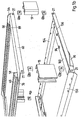
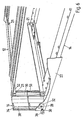
- FIG. 1 shows an exploded view of a frame module designed according to the invention for the construction of a case housing system in the sub-figures 1a and 1b, the frame module 10 comprising a first or upper base frame 12 and a second or lower base frame 14, which have four racks Profile pieces 16, 17, 18 and 19 can be rigidly connected by means of compression fittings 20 and then form a slide-in housing for an electronic device, the length of the rack profile pieces 16 to 19 being chosen differently depending on the height of the device to be inserted.
- These devices usually have a front plate 22 which projects on the right and left beyond the inner housing dimensions (“installation width”) of the device 24 by a piece A and has openings 28 in this area in order to attach the front plate 22 and thus the device 24 to corresponding metal profiles 16 again with the aid of a compression fitting 30, which usually consists of a square nut 32 which can be inserted into a correspondingly shaped T-shaped inner profile part 34, so that a screw 36 through the bore 28 of the front plate 22 and the profile slot 38 can be inserted and screwed into the square nut 32. In this way, a height-adjustable compression fitting can be reached.
- a so-called cage nut can also be used, which holds in the profile, even when the associated screw bolt 36 has been removed.
- fastening for example a hollow profile or an angular profile with threaded holes, in which, however, there is no continuous adjustability, but only an adjustability in steps in the spacing of the threaded holes.
- Fig. 4 again in an enlarged scale compared to the other figures in the partial figure a in cross-sectional view, which is initially a commercially available profile, but in each case a projection 40 or 42 has been milled off in order to obtain a system fit in the corner 44 or 46.
- the milling is preferably limited to an area 48 or 50 at one edge, see sub-figure b, the width of the milled area 48 or 50 having the width of the corresponding leg 52 of an L-profile, from which the respective frame 12 or 14 is composed.
- This results in an additional stiffening in the vertical direction due to positive locking.
- This applies to the protrusion 42 of FIG. 4a, while the protrusion 40 is preferably removed in its entire length, since the full length of the front plate 22 should lie in this area.
- FIG. 4b which shows a view from below of the profile rail of FIG. 4a
- FIG. 4c which is a view from the left of the rail shown in FIG. 4a.
- This feature results in a front panel edge system in the corner formed by the remaining projection and thereby results in a stiffening against parallelogram-like twisting with u.
- the clamping screws may not be fully tightened.
- the extent of the incisions 48 and 50 corresponds to the corresponding leg length D of the L-leg part 52, while the incision depth C is equal to the height of the projection 40 and is selected such that the leg part 52 on the two T- Legs are applied so that parallelism of the rack profile pieces (in the horizontal depth direction) is guaranteed.
- the height of the rack profile piece 16, designated X in FIG. 4c, depends, as already mentioned, on the device height to be accommodated.
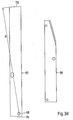
- the lower and upper base frames 12 and 14 are each constructed from four L-profile pieces 54, 56, 58 and 60 (or 154, 156, 158 and 160), which are expediently each have the same cross-sectional shape with different leg lengths D and E, see e.g. As Fig. 1a and the sub-figures 3a, 3b, and 3c. 3a shows the L-profiles 54 (left) and 154 (right), these are the rear L-profiles of the upper and lower frame 12 and 14. In contrast, FIG.
- FIG. 3b shows the L-profiles 156 or 160, this is the left or right side L-profile of the lower frame, while the front L-profile 158 of the un tere frame 14 corresponds to the rear L-profile 54 of the upper frame 12, see the left part of FIG. 3a, and the front L-profile 58 of the upper frame 12 corresponds to the rear L-profile 154 of the lower frame 14.
- FIG. 3c shows in its left half the L-profile of the identically constructed lateral L-profiles of the upper frame 12, reference numbers 56 and 60, respectively.
- leg parts lying one above the other are firmly connected to one another, for example, by riveting via bores 62, 64 in parts 58 and 60, respectively.
- the figures also show that two parallel (here, the longer) sides of the strips are provided with attached U-profiles, which are shown in Fig. 3c on the right side.
- U-profiles also referred to as closing profiles, have a W-shaped U-web profile, as can be clearly seen by cutting through 45 ° in FIG. 3c.
- This W-profiling 70 is arranged such that when an upper base frame 12 of a first module is interlockingly assembled with a lower base frame 14 of a second module placed above it, the W-profiles 66 and 68 of the two frames mesh with one another and thereby result in a locking in the vertical direction .
- the blocking in the horizontal direction parallel to the U-profile rails 66, 68 takes place in that the end edges 72 of the L-profile 58 of the upper frame 12 with the corresponding side edges 76 and 78 of the L-profiles 160 and 156 of the lower frame 14 of an attached module.
- the L-profile piece 58 and 154 shown on the right in FIG. 3a must be freed from the shorter leg at both ends over a length (E - W), where W is the wall thickness of the L-profile piece, so that results in a contact surface 101 projecting at right angles.
- the end faces of the shorter and thus projecting L-leg of the L-profile 154, 82 and 84 (the latter edge cannot be seen in FIG. 1a) of the lower frame 14 with corresponding edge surfaces 87 and 89 of the upper frame 12 of a lower module engaged.
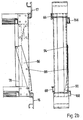
- FIG. 2a in which the corresponding mechanism can be clearly seen. It consists in each case of a pivot lever 86 articulated on the lateral L-profiles 156 and 160, which is rotatably mounted about a pivot point 88, for example in the form of a rivet, on the side of the longer leg facing away from the shorter leg of the L-profile.
- the arrangement is such that the corresponding L-profiles of the (in the embodiment shown shorter) frame sides 56 and 156 of interlocked base frames 12 and 14 of two different modules form a split T, the split T-leg directed towards the inside of the frame and there is so much play between them (this can be achieved by appropriate shape and arrangement of the U-profiles 66, 68 of the upper frame 12 and 166.168 of the lower frame 14) that the pivot lever 86 remains freely movable in this column.
- the swivel lever 86 has a type of handle 90 on its part protruding outwards from the T, which can be formed by simply bending the protruding part of the swivel lever 86 formed from a rectangular sheet-metal strip.
- the pivot lever 86 is articulated on a so-called locking lever 92 via an articulation point 94, the articulation allowing a slight axial displacement with respect to the longitudinal extent of the locking lever 92, for example in that a pin extending from the pivot point 94 of the pivot lever 86 extends into an elongated hole 96 within the locking lever 92.
- the locking lever 92 is in turn articulated at one end near an end of the L-profile 156 (which is distant from the pivoting lever 86), namely on the surface of the longer leg of the L-profile directed towards the shorter leg of the L-profile, see the articulation point 98 in Fig. 2a.
- the locking lever 92 lies in its locking rest position with its straight end face 95 (near its articulation point 98) on the surface of the shorter leg 118 facing away from the longer leg of the L-profile 154.
- the linkage can in turn be carried out with the aid of a rivet.
- This rivet simultaneously holds, together with further rivets 100, 102, 104, a holding plate 106 for a short wire spring 108, which presses against one side edge of the locking lever 92 and urges it into the locking position shown in FIG.
- the locking lever 92 When the bent part, that is to say the handle 90 of the actuating lever 86 has just reached the edge 126 of the L-profile 160, the locking lever 92 has about its pivot 98 pivoted so far in the direction of arrow 124 that the end face 116, which has a radius of curvature R around the articulation point 98, and a gap 93 for receiving the shorter leg of the L-profile 58 with the narrowest gap width W at points 76 and 78 in Fig. 1a, which point results from the dimension E - W, has disappeared below the longer leg of the L-profile 160 and has thus released the side surface 118.
- the lower frame 14 can now be pulled forward with respect to the upper frame 12 of a lower module, as a result of which its W-profiles 166 and 168, respectively, are released from the corresponding W-profiles 66, 68 of the other module and enable the two modules to be separated from one another.
- this release position fixable in a suitable manner in order to facilitate the handling of the arrangement.
- the fixation can take place, for example, in that a bore 128 is arranged on the end of the pivot lever 86 which has the handle 90 in such a way that this bore comes to lie exactly above the fastening rivet 130 in the unlocked state of the pivot rivet 130, so that this rivet 130 into the Bore 128 engages and holds the lever 86 in spite of the pressure of the spring 108.
- the bore 128 By slightly lifting the pivot lever 86 by means of the handle 90 (with reference to FIG. 2a from the plane of the drawing), the bore 128 can be released from the rivet mandrel of the rivet 130, whereupon the spring 108 presses the arrangement back into its locking position, which is shown in FIG 2a is shown.
- Fig. 2a also shows the attachment of the lower frame 14 to the rack sections 18 and 19 with the help of compression fittings 20, it also becomes clear how on the rack section 18 a front panel and a rack section 19, a rear wall or Like. Can be attached by inserting appropriate compression fittings 30 into the inner profile 34
- FIG. 3d the locking lever is shown on the left and the pivoting lever on the right, while in FIG. 3e the holding plate 106 can be seen, as is the wire spring 108 which is held by a spring holding plate 132 by the spring 108 is inserted into a slot 134, the spring being held on the one hand by the two walls of this slot 134, on the other hand by the holding plate 106 or by the inner surface of the longer leg of the L-profile on which the holding plate 106 is placed.
- the diameter of the spring wire 108 is slightly less than the thickness of the spring holding plate 132, so that the spring 108 can pivot freely between the holding plate 106 and the L-profile.
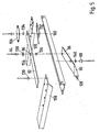
- FIG. 5 this structure is once again explained in an exploded view.
- a spacer sleeve 134 and a further spacer sleeve 136 can also be seen here as additional components, which also serve to ensure free movement of the locking lever 92, and a washer 138 can also be seen, which securely supports the locking lever 92 with respect to the elongated hole 96 ensures.
- the spacer sleeves 134 and 136 have different lengths, due to the fact that the spacer sleeve 136 must extend through the locking lever 92 and also the distance predetermined by the wall thickness w of the lateral L-profile 160 or 156 overcomes the swivel lever while the spacer sleeve 134 only allow the locking lever 92 free play.
- the further spacer sleeve 140 which is used for pivoting the pivot lever 86, also has the shorter dimensions of the spacer sleeve 134.
- the lengths of the spacer sleeves result as follows: the sleeves 134 and 140 have a length corresponding to the wall thickness of the lever 92 plus play.
- the sleeve 136 has a length that corresponds to the wall thickness of the lever and the wall thickness w of the L-profile, plus play.
- the housing system according to the invention represents a very versatile arrangement. In particular, it is possible to adapt the housing system to devices of different heights.
- a differently designed module can then be placed as the upper end, for example consisting of a lower base frame 14, on which a tape recorder, an obliquely running mixer, or other devices with operating or display surfaces on the top are then placed can be.
- stiffening rails 205 (not shown) can be attached to the rear in a completely analogous manner.
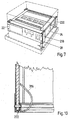
- the case bottom can be a case case 104 known per se, as shown in FIG. 8, consisting of a case bottom 206 with feet or rollers 208 and butterfly closures 210, this case bottom having only such a border that the device placed on the base frame 12 screwed to the case base is fully accessible.
- a dome-shaped case lid 212 or 214 can then be placed on this case bottom 206 with the aid of further butterfly closures (or similar closures), wherein different hood heights can be used depending on the device height.
- intermediate elements 216 between floor 206 and hood 212 or 214 if a larger tower height is built up.
- a corresponding intermediate element 216 of corresponding extension could be present for each device or also for each device group of a certain height, so that the combination or separation of systems results in an exact adaptation to the stack height provided.
- the housing frame such a dimension that there is an adaptation to, for example, 19-inch built-in cupboards.
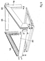
- additional support brackets can also be attached, for example on the rear side or, in the arrangement according to FIG. 9, also on the underside of the oblique rack profiles. It is also possible to attach slide rails in the simplest way to the lateral guide grooves 39 of the rack profiles by means of a clamp screw connection.
- brackets Due to the stiffening effect of the locking frame, such brackets will be dispensable in most cases.
- a great advantage of the housing system according to the invention is the fact that even if this housing system is adapted to 19-inch devices, devices which are not adapted to this 19-inch dimension are also integrated into a 19-inch formation by the special embodiment can, such as keyboards, mixers or computers, which are to work together with 19-inch devices, but themselves take on a different format, in particular a smaller format, namely through Mounting the second (lower) base frame 14 under a non-19 "device to be uppermost or by attaching the first (upper) base frame 12 and the second (lower) base frame 14 to a non-19" device to be inserted between the modules (or Device combination). This can be done both through horizontal and vertical openings (possibly elastically mounted). Such a combination can then be permanently wired and tested in the case housing system, which saves setup time at the application site.
- a 19-inch dimension (corresponding to 483 mm)
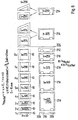
- it is favorable to provide certain height gradations for example height gradations of the dimension 1 3/4 inches corresponding to 44.45 mm, in which case the individual modules z. B. can have a height of 1 to 8 times this height unit, see Fig. 8, left side, for the modules, and right side for the case rings 216th
- the rack rail profile pieces as well as the L profiles are each commercially available finished products, so that for this reason the subject of the invention can be produced with very simple means.
- Aluminum has proven itself as a profile material, although steel sheet is also suitable for the L-profile rail, which is usually made from aluminum profiles with the dimensions 40 x 15 x 2 mm, because steel sheet can be punched and thus the manufacture of the various openings is made considerably easier.
- This also applies in particular to the locking lever (92) and the pivoting lever (86), whereby the distances between the punched-out portions of the locking lever (92) and the pivoting lever (86) should be adjusted to the same dimension, so that only one when creating the punching tools Replacing the appropriate stamps and dies would be required.
- the bottom cover of the case, 206 could then have a leg length of 40 mm, while the intermediate part or case ring 216 could have dimensions of 250, 375, 500, 625, etc., as required.
- the hood 212 in turn has z. B. a leg length of 80 mm, while the larger hood 214 has a leg length of 250 or 375 mm.
- a bracket 216 can be provided on the case ring or case hood corners, which one Has width and is so protruding that it comes into engagement with the lateral outer surface 218, 220 (Fig. 7) of the associated rack profile pieces 16 and thus results in a guide when putting the case elements.
- W-profile is also used in the case elements to stabilize the supporting edges of elements placed on top of one another, see reference number 222.
Landscapes
- Engineering & Computer Science (AREA)
- Microelectronics & Electronic Packaging (AREA)
- Casings For Electric Apparatus (AREA)
- Supply Devices, Intensifiers, Converters, And Telemotors (AREA)
Claims (16)
Priority Applications (1)
| Application Number | Priority Date | Filing Date | Title |
|---|---|---|---|
| AT85116140T ATE47268T1 (de) | 1984-12-29 | 1985-12-18 | Case-gehaeusesystem. |
Applications Claiming Priority (2)
| Application Number | Priority Date | Filing Date | Title |
|---|---|---|---|
| DE3447791 | 1984-12-29 | ||
| DE3447791A DE3447791A1 (de) | 1984-12-29 | 1984-12-29 | Case-gehaeusesystem |
Publications (2)
| Publication Number | Publication Date |
|---|---|
| EP0186857A1 EP0186857A1 (fr) | 1986-07-09 |
| EP0186857B1 true EP0186857B1 (fr) | 1989-10-11 |
Family
ID=6254101
Family Applications (1)
| Application Number | Title | Priority Date | Filing Date |
|---|---|---|---|
| EP85116140A Expired EP0186857B1 (fr) | 1984-12-29 | 1985-12-18 | Système de bâti à boîtiers |
Country Status (4)
| Country | Link |
|---|---|
| EP (1) | EP0186857B1 (fr) |
| JP (1) | JPS6263494A (fr) |
| AT (1) | ATE47268T1 (fr) |
| DE (2) | DE3447791A1 (fr) |
Families Citing this family (8)
| Publication number | Priority date | Publication date | Assignee | Title |
|---|---|---|---|---|
| DE8713244U1 (de) * | 1987-09-29 | 1987-11-26 | Haseke GmbH & Co KG, 4952 Porta Westfalica | Gehäuse |
| DE9203100U1 (de) * | 1992-03-09 | 1993-07-08 | Böwe Systec AG, 8900 Augsburg | Grundgestell für Maschinen u.dgl. |
| DE29704237U1 (de) * | 1997-03-08 | 1997-05-28 | DMT GmbH Feinwerktechnische Komplettlösungen, 71034 Böblingen | Gerätegehäuse |
| DE19736026C1 (de) | 1997-08-20 | 1998-10-22 | Dmt Gmbh Feinwerktechnische Ko | Gerätegehäuse |
| CN113876129B (zh) * | 2016-04-22 | 2023-01-31 | 川湖科技股份有限公司 | 托架装置 |
| CN108488594A (zh) | 2018-03-26 | 2018-09-04 | 京东方科技集团股份有限公司 | 一种连接件及显示设备 |
| CN108899779B (zh) * | 2018-08-27 | 2024-07-02 | 江苏南瑞帕威尔电气有限公司 | 一种加强型开关柜后门及加强型开关柜 |
| CN114842761B (zh) * | 2022-04-20 | 2025-02-11 | 江苏新视界显示技术有限公司 | 一种led大屏幕计算机辅助设计的方法和装置 |
Family Cites Families (4)
| Publication number | Priority date | Publication date | Assignee | Title |
|---|---|---|---|---|
| GB1101356A (en) * | 1964-05-04 | 1968-01-31 | C & N Electrical Ltd | Improvements in or relating to structural members and arrangements, particularly for use with modular units of equipment |
| DE1977522U (de) * | 1967-10-19 | 1968-01-25 | Schaefer Kg Fritz | Regaleinheit. |
| BE790329A (fr) * | 1971-10-21 | 1973-04-19 | Imhof Bedco Ltd | Structure rigide perfectionnee |
| US4123129A (en) * | 1976-11-18 | 1978-10-31 | Tektronix, Inc. | Modular electronic instrument cabinets |
-
1984
- 1984-12-29 DE DE3447791A patent/DE3447791A1/de not_active Withdrawn
-
1985
- 1985-12-18 DE DE8585116140T patent/DE3573703D1/de not_active Expired
- 1985-12-18 AT AT85116140T patent/ATE47268T1/de not_active IP Right Cessation
- 1985-12-18 EP EP85116140A patent/EP0186857B1/fr not_active Expired
- 1985-12-27 JP JP60299678A patent/JPS6263494A/ja active Pending
Also Published As
| Publication number | Publication date |
|---|---|
| ATE47268T1 (de) | 1989-10-15 |
| JPS6263494A (ja) | 1987-03-20 |
| EP0186857A1 (fr) | 1986-07-09 |
| DE3447791A1 (de) | 1986-07-10 |
| DE3573703D1 (en) | 1989-11-16 |
Similar Documents
| Publication | Publication Date | Title |
|---|---|---|
| DE69402525T2 (de) | Gerüst mit variabler grösse für elektrische und/oder elektronische anlage | |
| EP3150781B1 (fr) | Dispositif de cabine sanitaire | |
| EP0186857A1 (fr) | Système de bâti à boîtiers | |
| DE3879497T2 (de) | Metallstuetze. | |
| DE2814713A1 (de) | Zerlegbare trennwand | |
| DE4414215A1 (de) | Zusammensetzbarer Behälter | |
| DE60021295T2 (de) | Rahmenprofil fur Rahmenmontagesystem für Anzeigetafeln, um aufeinanderfolgende und sich wiederholende Bildserien darzustellen | |
| WO2008092699A1 (fr) | Dispositif d'inspection, en particulier élément de recouvrement d'inspection | |
| EP0628498A1 (fr) | Conteneur | |
| DE2648272C3 (de) | Bauelementesatz zur Erstellung von Schutzschränken im Baukausten-System | |
| DE1591623B1 (de) | Schrank fuer Geraete der Nachrichtentechnik | |
| DE10144028A1 (de) | Maschinengestell in Modulbauweise | |
| DE8438262U1 (de) | Case-Gehäusesystem | |
| DE2624632A1 (de) | Transportable, zerlegbare raumzelle | |
| DE2718135A1 (de) | Schalungstraeger fuer den betonbau | |
| DE69516956T2 (de) | Modularer Umfassungs-Satz zum Abgrenzen eines erweiterbaren, umschlossenen Rauminhaltes | |
| DE4220844C2 (de) | Standgestell für ein Gehäuse, insbesondere einer Briefkasten- und/oder Türsprechanlage | |
| EP3276099B1 (fr) | Conteneur de transport | |
| DE1591623C (de) | Schrank fur Gerate der Nachrichten techmk | |
| DE2836379C3 (de) | Palette | |
| DE3606888A1 (de) | Transportables schutzhaus | |
| DE19615447A1 (de) | Wandsystem insbesondere für Messestände | |
| EP1043821A2 (fr) | Armoire électrique avec montants et charnière | |
| DE3304267C2 (fr) | ||
| DE7915574U1 (de) | Bauelementesatz für Rahmengestelle |
Legal Events
| Date | Code | Title | Description |
|---|---|---|---|
| PUAI | Public reference made under article 153(3) epc to a published international application that has entered the european phase |
Free format text: ORIGINAL CODE: 0009012 |
|
| AK | Designated contracting states |
Kind code of ref document: A1 Designated state(s): AT BE CH DE FR GB IT LI LU NL SE |
|
| 17P | Request for examination filed |
Effective date: 19860708 |
|
| 17Q | First examination report despatched |
Effective date: 19880511 |
|
| GRAA | (expected) grant |
Free format text: ORIGINAL CODE: 0009210 |
|
| AK | Designated contracting states |
Kind code of ref document: B1 Designated state(s): AT BE CH DE FR GB IT LI LU NL SE |
|
| PG25 | Lapsed in a contracting state [announced via postgrant information from national office to epo] |
Ref country code: SE Effective date: 19891011 Ref country code: NL Effective date: 19891011 Ref country code: IT Free format text: LAPSE BECAUSE OF FAILURE TO SUBMIT A TRANSLATION OF THE DESCRIPTION OR TO PAY THE FEE WITHIN THE PRESCRIBED TIME-LIMIT;WARNING: LAPSES OF ITALIAN PATENTS WITH EFFECTIVE DATE BEFORE 2007 MAY HAVE OCCURRED AT ANY TIME BEFORE 2007. THE CORRECT EFFECTIVE DATE MAY BE DIFFERENT FROM THE ONE RECORDED. Effective date: 19891011 Ref country code: GB Effective date: 19891011 Ref country code: FR Free format text: THE PATENT HAS BEEN ANNULLED BY A DECISION OF A NATIONAL AUTHORITY Effective date: 19891011 Ref country code: BE Effective date: 19891011 |
|
| REF | Corresponds to: |
Ref document number: 47268 Country of ref document: AT Date of ref document: 19891015 Kind code of ref document: T |
|
| REF | Corresponds to: |
Ref document number: 3573703 Country of ref document: DE Date of ref document: 19891116 |
|
| PG25 | Lapsed in a contracting state [announced via postgrant information from national office to epo] |
Ref country code: AT Effective date: 19891218 |
|
| PG25 | Lapsed in a contracting state [announced via postgrant information from national office to epo] |
Ref country code: LU Free format text: LAPSE BECAUSE OF NON-PAYMENT OF DUE FEES Effective date: 19891231 Ref country code: LI Effective date: 19891231 Ref country code: CH Effective date: 19891231 |
|
| PGFP | Annual fee paid to national office [announced via postgrant information from national office to epo] |
Ref country code: DE Payment date: 19900103 Year of fee payment: 5 |
|
| EN | Fr: translation not filed | ||
| NLV1 | Nl: lapsed or annulled due to failure to fulfill the requirements of art. 29p and 29m of the patents act | ||
| GBV | Gb: ep patent (uk) treated as always having been void in accordance with gb section 77(7)/1977 [no translation filed] | ||
| PLBE | No opposition filed within time limit |
Free format text: ORIGINAL CODE: 0009261 |
|
| STAA | Information on the status of an ep patent application or granted ep patent |
Free format text: STATUS: NO OPPOSITION FILED WITHIN TIME LIMIT |
|
| REG | Reference to a national code |
Ref country code: CH Ref legal event code: PL |
|
| 26N | No opposition filed | ||
| PG25 | Lapsed in a contracting state [announced via postgrant information from national office to epo] |
Ref country code: DE Effective date: 19911203 |