EP0186878A1 - Presswerkzeug - Google Patents
Presswerkzeug Download PDFInfo
- Publication number
- EP0186878A1 EP0186878A1 EP85116343A EP85116343A EP0186878A1 EP 0186878 A1 EP0186878 A1 EP 0186878A1 EP 85116343 A EP85116343 A EP 85116343A EP 85116343 A EP85116343 A EP 85116343A EP 0186878 A1 EP0186878 A1 EP 0186878A1
- Authority
- EP
- European Patent Office
- Prior art keywords
- plate
- press
- adjusting plate
- adjusting
- pressing
- Prior art date
- Legal status (The legal status is an assumption and is not a legal conclusion. Google has not performed a legal analysis and makes no representation as to the accuracy of the status listed.)
- Granted
Links
- 238000003825 pressing Methods 0.000 title claims abstract description 53
- 239000000463 material Substances 0.000 claims abstract description 11
- 238000004519 manufacturing process Methods 0.000 claims description 6
- 238000005520 cutting process Methods 0.000 claims description 4
- 238000000227 grinding Methods 0.000 claims description 4
- 238000007493 shaping process Methods 0.000 abstract 2
- 230000006835 compression Effects 0.000 description 7
- 238000007906 compression Methods 0.000 description 7
- 238000000034 method Methods 0.000 description 4
- 238000005429 filling process Methods 0.000 description 3
- 230000000284 resting effect Effects 0.000 description 3
- PEDCQBHIVMGVHV-UHFFFAOYSA-N Glycerine Chemical compound OCC(O)CO PEDCQBHIVMGVHV-UHFFFAOYSA-N 0.000 description 2
- 239000012530 fluid Substances 0.000 description 2
- 235000011187 glycerol Nutrition 0.000 description 1
- 239000008187 granular material Substances 0.000 description 1
- 239000002245 particle Substances 0.000 description 1
- 238000007789 sealing Methods 0.000 description 1
- 238000009423 ventilation Methods 0.000 description 1
Images



Classifications
-
- B—PERFORMING OPERATIONS; TRANSPORTING
- B30—PRESSES
- B30B—PRESSES IN GENERAL
- B30B15/00—Details of, or accessories for, presses; Auxiliary measures in connection with pressing
- B30B15/02—Dies; Inserts therefor; Mounting thereof; Moulds
- B30B15/022—Moulds for compacting material in powder, granular of pasta form
Definitions
- the present invention relates to a pressing tool with a lower pressing plate which is movable in a vertical direction in a pressing ring, the upper side of which forms a shape for the material to be pressed with the pressing ring, an adjusting plate arranged below the lower pressing plate, on the upper side of which the lower pressing plate rests with its underside and which is adjustable in its inclination to the longitudinal axis of the pressing tool, a base plate arranged below the adjusting plate and connected to the adjusting plate by connecting elements, the upper side of which engages with the underside of the adjusting plate, and an upper pressing plate cooperating with the lower pressing plate.
- Pressing tools of the type mentioned are known as components of hydraulic presses.
- the lower press plates are arranged in bushings, the so-called press rings, which are mostly embedded in tool tables.
- the shape of the compact is determined by the press ring and formed by the upper side of the lower press plate which is movable in the vertical direction in the press ring and which is lowered during the filling process with the material to be pressed.
- the mold is filled by means of a filling funnel, which is fitted with the material to be pressed and is slidably mounted above the tool table, the lower opening of which runs a short distance above the tool table.
- the filling funnel has approximately the same width as the tool table, so that the molds attached in the tool table can be filled in a single operation if the filling funnel is guided away over the tool table.
- a scraper resting on the tool table is attached to the filling funnel and, after the filling process, wipes off the material that protrudes beyond the mold edge in order to achieve a uniform filling of the mold.
- the tool table is moved under an upper tool provided with corresponding upper press plates. After the pressing process has ended, the upper tool is raised, the tool table is brought into its starting position and the finished compact is ejected from the mold by lifting the lower press plate.
- the scraper movement of the scraper brings about a higher filling density of the press material in a previously unavoidable manner, especially when processing granular press material in certain areas of the mold. This is usually the area near the edge of the mold over which the stripper travels in the last phase of its stripping motion.
- uneven compression in certain areas cannot be accepted, for which reference is made, for example, to highly sensitive electronic components and to cutting and grinding wheels, in which extremely small irregularities lead to imbalance.
- an adjustment plate with an inclination to the longitudinal axis of the press tool is therefore provided below the lower press plate in press tools of the type described. This adjustment plate is connected to a base plate located below the adjustment plate by mostly three screws evenly distributed on it.
- the screws or bores can be arranged offset by 120 °.
- one of the screws is arranged so that it lies on an imaginary line which, starting from the center of the circular shape, corresponds to the direction of movement of the scraper.
- the screw is attached in the edge region of the mold, in which a higher compression results from the stripping movement of the stripper.
- the present invention seeks these disadvantages loading malli g en and sees its task is to provide a pressing tool available, at which the adjusting plate is adjustable in its inclination to the longitudinal axis of the pressing tool without the complicated removing the lower press plate.
- the invention provides the characterizing features of claim 1 in a pressing tool of the type described above.
- the present invention allows the adjustment of the setting plate without removing the lower press plate and thus leads to a drastic reduction in the times previously required for setting up the tools.
- the adjustment plate of the pressing tool according to the invention can be adjusted in its inclination, so that the filling height of the pressing tool changes at the desired points, which compensates for the higher filling density at these points and thus, for example, the imbalance in the manufacture of a grinding wheel is counteracted.
- the piston of the lifting device is arranged so that it is directed against the base plate, during the cylinder forming a unit with the adjusting plate which is moved towards the adjustment plate in the direction of the lower press plate.
- one or more lifting devices are provided in the region of the base plate adjacent to the setting plate, the lifting device works by moving the piston acting on the underside of the setting plate up and down.
- the present invention provides for the arrangement of a plurality of lifting devices in order to enable the production of such workpieces in special problem cases, in which high uniformity is particularly important, it has proven sufficient for many applications to provide only one lifting device which is expedient is arranged in the mold region near the edge, over which the stripper is guided in the last phase of its stripping movement.
- the lifting device is arranged in such a way that the center of the lifting device lies on the radius which, starting from the center of the lower pressing tool, is congruent with the direction of movement of the hopper or the scraper.
- the base plate and adjusting plate are expediently connected by connecting elements, such as screw bolts or hinges.
- the screw bolts and lifting device are arranged in such a way that the Bolts form the two end points of the base line of an isosceles triangle and the lifting device lies with its center exactly on the perpendicular to the base line of this triangle.
- the screw bolts In order to have a certain freedom of movement for the adjustment of the adjustment plate, the screw bolts must not be tightened firmly and thus form a tipping point for the adjustment plate.
- Compression springs preferably in the form of disc springs in recesses, which are provided in the area of the base plate adjacent to the setting plate above the threaded holes, press the setting plate against the screw heads.
- the screw connection of the base and adjustment plate described above can be replaced by a hinge connection.
- An arrangement of two individual hinges instead of the described bolts is possible as well as the arrangement of an individual hinge of appropriate length, which is to be fixed around a safe tipping point, preferably with its long side at right angles to a line leading through the center of the lifting device and base plate .
- An embodiment of the present invention has proven to be particularly suitable, in which the piston of the lifting device acting against the adjusting plate or base plate is not flat on the end face but spherical.
- the present invention is particularly suitable for the production of compacts, which are made of granular material to be pressed.
- the present invention is particularly suitable for the production of cutting and grinding wheels.
- Known hydraulic fluids in particular glycerin, are suitable for filling the hydraulic lifting device.
- the hydraulic press (20) shown in FIG. 1 can be loaded on both sides.
- the press rings (18, 18a), in which the lower press plates (19, 19a) are arranged, are let into tool tables (13, 13a).
- Filling hoppers (14, 14a) are used to fill the molds formed from press rings (18, 18a) and lower press plate (19, 19a).
- Strippers (15, 15a) are attached to the filling funnels (14, 14a).
- Press mandrels (40) are used to create a center hole in the manufacture of cutting discs.
- Figure 2 shows a partially shown tool table (13), in which in the left half of the figure according to the known prior art three screw bolts (16), see.
- Figure 3 of which screw heads (38) are shown for adjusting the adjustment plate (1) and for fastening it to the base plate (2).
- a pressing tool according to the invention in which a lifting device (3) opposite in the base plate (2) lying area (17) of the adjusting plate (1) (see FIG. 4) is arranged for adjusting the adjusting plate (1).
- the inclination of the adjusting plate (1) can be adjusted by actuating the lifting device (3), so that the lower pressing plate (19) (FIG. 4) resting on the adjusting plate (1) also has a different inclination and is thus identified by the arrows Area gives a different fill level of the shape.
- an arrow A indicates the direction of movement of the hopper and scraper. Screws (16), of which only screw heads (38) are shown (see FIGS.
- FIG 3 shows a pressing tool (5) according to the known prior art.
- a press ring (18) is inserted, in which the lower press plate (19), which cooperates with the upper press plate (26), is movable in the vertical direction to eject the compact, not shown, and to change the thickness of the compact .
- the top (6) of the lower press plate (19) forms together with the press ring (18) the shape for the compact.
- Below the lower press plate (19) the adjustment plate (1) is arranged, on the upper side (4) of the press plate (19) with its underside (41). Underneath is the base plate (2), the top (29) of which engages with the bottom (34) of the adjustment plate (1) via compression springs (disc springs).
- Magnets (23) connect the lower press plate (19) and the adjusting plate (1) in order to enable a safe lowering of the lower press plate (19) even if particles of the material to be pressed have reached between the press ring (18) and the lower press plate (19) .
- the lower press plate (19) must be dismantled, by loosening or tightening the screw bolts (16), the angle a that the level formed by the upper end face (4) of the adjustment plate (1) with Longitudinal axis L of the press tool (5) forms to be able to adjust.
- the bolts (16) are screwed into threaded holes (25) in the base plate (2).
- the compression springs (24) in recesses (27) press the setting plate (1) against the screw heads (38).
- the base plate (2) rests on a lifting plate (22) which is guided in columns, not shown. There is a small gap between the press ring (18) and the side edges of the lower press plate (19) to prevent the lower press plate (19) from jamming in the press ring (18) when its inclination is changed via the setting of the adjusting plate (1) .
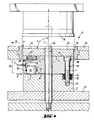
- the pressing tool (5) according to the invention shown in FIG. 4 is distinguished from the device shown in FIG. 3 by a lifting device (3) which is arranged in the region (17) of the adjusting plate (1) opposite the base plate (2) is not.
- the lifting device (3) is actuated with the master cylinder (8) shown in FIG. (6) via the hose / pipe (7).
- a closable bore (28) serves to vent the lifting device (3).
- the lifting device (3) consists essentially of a piston (30) and a cylinder (31) in which the piston (30) presses against the upper side (29) of the base plate (2).
- the seal between the cylinder (31) and piston (30) is made by sealing rings (32).
- the pressure of the piston (30) creates a wedge gap between the adjusting plate (1) and the base plate (2) at the point marked with an arrow S.
- the angle ⁇ is adjusted, which is formed by the plane formed from the upper side (4) of the adjusting plate (1) and the longitudinal axis L of the pressing tool.
- Magnets (23), only one of which is shown, connect the adjusting plate (1) and the lower press plate.
- Screw bolts (16), of which only one is also shown, serve as in the known pressing tool to connect the adjusting plate (1) and base plate (2), but are not tightened as in the known pressing tools, so that a certain freedom of movement for the Adjustment of the adjustment plate is given.
- the functions of the lifting plate (22) and the upper press plate (26) correspond to the embodiment of the known press tool described in FIG. 3.
- FIG. 5 shows a further embodiment of a pressing tool according to the invention, in which the lifting device (3) is arranged in the region (33) of the base plate (2) opposite the setting plate (1) is not.
- the piston (30) presses against the underside (34) of the adjusting plate (1) and thereby causes a different inclination of the adjusting plate (1) or the lower pressing plate resting thereon.
- this embodiment of the pressing tool corresponds to the embodiment described for FIG. 4.
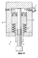
- the master cylinder (8) shown in FIG. 6 consists of a cylinder housing (11) and a piston (10) which can be adjusted in the cylinder housing against the pressure of the spring (9).
- the piston (10) is adjusted by means of a threaded screw (12).
- a connection point (36) is used to connect the hose / pipe (7).
- a closable bore (39) is provided for ventilation.
Landscapes
- Engineering & Computer Science (AREA)
- Mechanical Engineering (AREA)
- Press Drives And Press Lines (AREA)
- Measurement Of The Respiration, Hearing Ability, Form, And Blood Characteristics Of Living Organisms (AREA)
- Treatment Of Fiber Materials (AREA)
- Casting Or Compression Moulding Of Plastics Or The Like (AREA)
Abstract
Description
- Die vorliegende Erfindung betrifft ein Preßwerkzeug mit einer in einem Preßring in vertikaler Richtung beweglichen unteren Preßplatte, deren Oberseite mit dem Preßring eine Form für das zu verpressende Material bildet, einer unterhalb der unteren Preßplatte angeordneten Einstellplatte, auf deren Oberseite die untere Preßplatte mit ihrer Unterseite aufliegt und die in ihrer Neigung zur Längsachse des Preßwerkzeuges verstellbar ist, einer unterhalb der Einstellplatte angeordneten und durch Verbindungselemente mit der Einstellplatte verbundenen Basisplatte, deren Oberseite mit der Unterseite der Einstellplatte in Eingriff steht, sowie einer mit der unteren Preßplatte zusammenwirkenden oberen Preßplatte.
- Preßwerkzeuge der genannten Art sind als Bestandteile hydraulischer Pressen bekannt. Die unteren Preßplatten sind in Buchsen, den sogenannten Preßringen, angeordnet, die, zumeist zu mehreren nebeneinanderliegend, in Werkzeugtischen eingelassen sind. Die Form des Preßlings wird durch den Preßring und durch die Oberseite der im Preßring in vertikaler Richtung beweglichen unteren Preßplatte gebildet, die beim Füllvorgang mit dem zu verpressenden Material abgesenkt ist. Die Füllung der Form erfolgt durch einen mit dem zu verpressenden Material gefüllten, oberhalb des Werkzeugtisches verschiebbar angebrachten Fülltrichter, dessen untere öffnung in geringem Abstand oberhalb des Werkzeugtisches verläuft. Der Fülltrichter hat in etwa die gleiche Breite wie der Werkzeugtisch, so daß die Füllung der im Werkzeugtisch angebrachten Formen in einem einzigen Arbeitsgang erfolgen kann, wenn der Fülltrichter über den Werkzeugtisch weggeführt wird. Am Fülltrichter ist ein auf dem Werkzeugtisch aufliegender Abstreifer angebracht, der nach dem Füllvorgang das über den Formenrand hinausragende Material zur Erzielung einer gleichmäßigen Füllung der Form abstreift. Nach Beendigung des Füllvorganges wird der Werkzeugtisch unter ein mit entsprechenden oberen Preßplatten versehenes Oberwerkzeug verschoben. Nach Beendigung des Preßvorganges wird das Oberwerkzeug angehoben, der Werkzeugtisch in seine Ausgangsposition gebracht und der fertige Preßling durch Anheben der unteren Preßplatte aus der Form ausgestossen.
- Die Abstreifbewegung des Abstreifers bewirkt in einer bisher noch nicht vermeidbaren Weise, insbesondere bei der Verarbeitung von körnigem Preßmaterial in bestimmten Bereichen der Form eine höhere Fülldichte des Preßmaterials. Zumeist ist dies der nahe dem Formenrand liegende Bereich, über den der Abstreifer in der letzten Phase seiner Abstreifbewegung fährt. Bei einer Vielzahl technischer Produkte kann eine ungleichmäßige Verdichtung in bestimmten Bereichen jedoch nicht in Kauf genommen werden, wozu beispielsweise auf hochempfindliche elektronische Bauteile und auf Trenn- und Schruppschleifscheiben verwiesen wird, bei denen bereits äußerst geringe Ungleichmäßigkeiten zur Unwucht führen. Zum Ausgleich einer ungleichmäßigen Verdichtung ist daher bei Preßwerkzeugen der beschriebenen Art eine in ihrer Neigung zur Längsachse des Preßwerkzeugs verstellbare Einstellplatte unterhalb der unteren Preßplatte vorgesehen. Diese Einstellplatte ist durch zumeist drei gleichmäßig auf ihr verteilte Schrauben mit einer unterhalb der Einstellplatte befindlichen Basisplatte verbunden. Bei einer beispielsweise kreisförmigen Form können die Schrauben bzw. Bohrungen um 120° versetzt angeordnet sein. üblicherweise ist eine der Schrauben dabei so angeordnet, daß sie auf einer gedachten Linie liegt, die, ausgehend vom Mittelpunkt der kreisförmigen Form, der Bewegungsrichtung des Abstreifers entspricht. Die Schraube ist dabei in dem Randbereich der Form angebracht, in dem durch die Abstreifbewegung des Abstreifers eine höhere Verdichtung entsteht. Durch entsprechendes Lösen und Anziehen von zumeist nur dieser einen Schraube ist die Neigung der Eintellplatte zur Längsachse des Preßwerkzeuges veränderbar, d.h. die Einstellplatte und mit ihr die untere Preßplatte wird in diesem Bereich leicht angehoben, wodurch sich in diesem Bereich eine etwas geringere Füllhöhe der Form ergibt. Die lokal erfolgende Verdichtung wird dadurch ausgeglichen. Um die Neigung der unteren Preßplatte verändern zu können, ohne daß sie im Preßring verkantet, ist es nötig, zwischen Preßring und unterer Preßplatte einen geringen Spalt vorzusehen. Da in diesen Spalt in an sich unvermeidbarer Weise auch das zu verpressende Material geraten kann, sind auf der Oberseite der Einstellplatte Permanentmagnete angebracht, die beim Absenken der unteren Preßplatte eine sichere Verbindung zwischen Einstellplatte und unterer Preßplatte bewirken und einem Verklemmen der unteren Preßplatte durch in den Spalt zwischen unterer Preßplatte und Preßring eingetretenes Material entgegenwirken.
- Die Formulierung "Veränderung der Neigung der Einstellplatte zur Längsachse des Preßwerkzeuges" drückt im Rahmen von Ansprüchen und Beschreibung der vorliegenden Erfindung aus, daß durch Anheben oder Absenken an einer oder mehreren Stellen der Einstellplatte, diese so verstellt wird, daß sich dabei der Winkel verändert, der von der Längsachse des Preßwerkzeuges und der von der oberen Stirnseite der Einstellplatte gebildeten Ebene gebildet wird.
- Der Nachteil dieser bekannten Preßwerkzeuge besteht darin, daß eine Neueinstellung der Einstellplatte den Ausbau der unteren Preßplatte erfordert, um die in der Einstellplatte angebrachten Schrauben verstellen zu können. Da Neueinstellungen nicht nur bei Formenwechsel, sondern in der Regel auch bei Beginn der Verarbeitung einer neuen Charge von Preßmaterial erforderlich sind und die Genauigkeit der Einstellung zudem nur empirisch überprüfbar ist und die Einstellung daher unter Umständen korrigiert werden muß, entstehen erhebliche, kostenverursachende Stillstandszeiten an den betreffenden Maschinen.
- Die vorliegende Erfindung will diese Nachteile be- seitigen und sieht ihre Aufgabe darin, ein Preßwerkzeug zur Verfügung zu stellen, bei dem die Einstellplatte in ihrer Neigung zur Längsachse des Preßwerkzeuges ohne den umständlichen Ausbau der unteren Preßplatte verstellbar ist.
- Zur Lösung dieser Aufgabe sieht die Erfindung bei einem Preßwerkzeug der eingangs beschriebenen Art die kennzeichnenden Merkmale von Anspruch 1 vor.
- Die vorliegende Erfindung gestattet die Verstellung der Einstellplatte ohne Ausbau der unteren Preßplatte und führt damit zu einer drastischen Verminderung der bisher notwendigen Zeiten für das Einrichten der Werkzeuge. Durch einfaches Verstellen des Kolbens des Geberzylinders z.B. mittels einer Stellschraube kann die Einstellplatte des erfindungsgemäßen Preßwerkzeuges in ihrer Neigung verstellt werden, so daß die Füllhöhe des Preßwerkzeuges sich an den gewünschten Stellen verändert, wodurch an diesen Stellen ein Ausgleich für die höhere Fülldichte geschaffen wird und damit beispielsweise der Unwucht bei der Herstellung einer Schleifscheibe entgegengewirkt wird.
- Sind gemäß der vorliegenden Erfindung eine oder mehrere Hubvorrichtungen in dem der Basisplatte gegenüberliegenden Bereich der Einstellplatte angeordnet, ist der Kolben der Hubvorrichtung so angeordnet, daß er gegen die Basisplatte gerichtet ist, während der eine Einheit mit der Einstellplatte bildende Zylinder zur Verstellung der Einstellplatte in Richtung der unteren Preßplatte verschoben wird.
- Sind gemäß einer weiteren Ausführungsform der vorliegenden Erfindung eine oder mehrere Hubvorrichtungen in dem der Einstellplatte benachbarten Bereich der Basisplatte vorgesehen, arbeitet die Hubvorrichtung durch Auf- und Abwärtsbewegung des auf die Unterseite der Einstellplatte wirkenden Kolbens.
- Wenngleich die vorliegende Erfindung die Anordnung mehrerer Hubvorrichtungen vorsieht, um in besonderen Problemfällen die Herstellung solcher Werkstücke zu ermöglichen, bei denen es in besonderer Weise auf eine hohe Gleichmäßigkeit ankommt, hat es sich für viele Anwendungszwecke als ausreichend erwiesen, lediglich eine Hubvorrichtung vorzusehen, die zweckmäßigerweise in dem randnahen Formenbereich angeordnet ist, über den der Abstreifer in der letzten Phase seiner Abstreifbewegung geführt wird. Die Anordnung der Hubvorrichtung erfolgt dabei so, daß der Mittelpunkt der Hubvorrichtung auf dem Radius liegt, der vom Mittelpunkt des unteren Preßwerkzeuges ausgehend, deckungsgleich mit der Bewegungsrichtung des Fülltrichters bzw. des Abstreifers ist. Bei einem solchen Preßwerkzeug sind Basisplatte und Einstellplatte zweckmäßigerweise durch Verbindungselemente, wie Schraubenbolzen oder Scharniere verbunden. Erfolgt die Verbindung von Basis- und Einstellplatte durch Schraubenbolzen, wobei bevorzugt zwei Schraubenbolzen vorzusehen sind, erfolgt gemäß einer zweckmäßigen Ausführungsform die Anordnung von Schraubenbolzen und Hubvorrichtung so, daß die Schraubenbolzen die beiden Endpunkte der Basislinie eines gleichschenkligen Dreiecks bilden und die Hubvorrichtung mit ihrem Mittelpunkt genau auf der Mittelsenkrechten der Basislinie dieses Dreiecks liegt. Um noch einen gewissen Bewegungsspielraum für die Verstellung der Einstellplatte zu haben, dürfen die Schraubenbolzen nicht fest angezogen werden und bilden auf diese Weise einen Kippunkt für die Einstellplatte. Druckfedern vorzugsweise in der Form von Tellerfedern in Ausnehmungen, die in dem der Einstellplatte benachbarten Bereich der Basisplatte oberhalb der Gewindebohrungen angebracht sind, drücken die Einstellplatte gegen die Schraubenköpfe.
- Gemäß einer weiteren Ausführungsform vorliegender Erfindung kann die vorstehend beschriebene Schraubverbindung von Basis- und Einstellplatte durch eine Scharnierverbindung ersetzt werden. Es ist sowohl eine Anordnung von zwei Einzelscharnieren statt der beschriebenen Schraubenbolzen möglich als auch die Anordnung eines Einzelscharniers von entsprechender Länge, das um einen sicheren Kippunkt festzulegen, vorzugsweise mit seiner Längsseite im rechten Winkel zu einer durch den Mittelpunkt von Hubvorrichtung und Basisplatte führenden Linie anzuordnen ist.
- Als besonders geeignet hat sich eine Ausführungsform der vorliegenden Erfindung erwiesen, bei dem der gegen Einstellplatte oder Basisplatte wirkende Kolben der Hubvorrichtung stirnseitig nicht eben ausgebildet ist sondern ballig.
- Besonders geeignet ist die vorliegende Erfindung bei der Herstellung von Preßlingen, die aus körnigem, zu verpressendem Material hergestellt werden. Ganz besonders ist die vorliegende Erfindung bei der Herstellung von Trenn- und Schruppschleifscheiben geeignet.
- Zur Füllung der hydraulischen Hubvorrichtung sind an sich bekannte Hydraulikflüssigkeiten geeignet, insbesondere Glyzerin.
- Die nachfolgenden Figuren dienen der näheren Erklärung der Erfindung, ohne die Erfindung auf die gezeigten Ausführungsformen zu beschränken.
- Es zeigen:
- Figur 1: die Aufsicht auf eine hydraulische Presse,
- Figur 2: die Aufsicht auf einen nur teilweise dargestellten Werkzeugtisch mit abgehobenen unteren Preßplatten,
- Figur 3: die Seitenansicht auf ein Preßwerkzeug entsprechend dem bekannten Stand der Technik, bei dem der untere Teil im Längsschnitt dargestellt ist, entlang der Linie III - III von Figur 2,
- Figur 4: die Seitenansicht auf ein Preßwerkzeug entsprechend der vorliegenden Erfindung, bei dem der untere Teil im Längsschnitt dargestellt ist, entlang der Linie IV - IV von Figur 2,
- Figur 5: die Seitenansicht auf ein Preßwerkzeug entsprechend einer weiteren Ausführungsform der vorliegenden Erfindung, bei dem der untere Teil im Längsschnitt dargestellt ist,
- Figur 6: einen im Schnitt dargestellten Geberzylinder zur Einstellung der unteren Preßplatte bei einem Preßwerkzeug gemäß vorliegender Erfindung.
- Die in Figur 1 gezeigte hydraulische Presse (20) ist beidseitig beschickbar. In Werkzeugtischen (13,13a) sind die Preßringe (18,18a) eingelassen, in denen die unteren Preßplatten (19,19a) angeordnet sind. Fülltrichter (14,14a) dienen zur Füllung der aus Preßringen (18,18a) und unteren Preßplatte (19,19a) gebildeten Formen. An den Fülltrichtern (14,14a) sind Abstreifer (15,15a) angebracht. Im Bereich (21) der hydraulischen Presse (20) sind für jede Seite separate, nicht dargestellte obere Preßwerkzeuge angeordnet. Preßdorne (40) dienen der Erstellung eines Mittelloches bei der Herstellung von Trennscheiben.
- Figur 2 zeigt einen nur teilweise dargestellten Werkzeugtisch (13), bei dem in der linken Hälfte der Figur entsprechend dem bekannten Stand der Technik drei Schraubenbolzen (16), s. Figur 3, von denen Schraubenköpfe (38) dargestellt sind zur Justierung der Einstellplatte (1) und zu deren Befestigung mit der Basisplatte (2) dienen.
- Im rechten Teil der Figur 2 ist ein erfindungsgemäßes Preßwerkzeug dargestellt, bei dem eine Hubvorrichtung (3), die im der Basisplatte (2) gegenüberliegenden Bereich (17) der Einstellplatte (1) (s. Figur 4) angeordnet ist, zur Justierung der Einstellplatte (1) dient. Durch Betätigung der Hubvorrichtung (3) läßt sich die Neigung der Einstellplatte (1) verstellen, so daß auch die auf der Einstellplatte (1) aufliegende untere Preßplatte (19) (Figur 4) eine andere Neigung bekommt und sich damit in dem durch Pfeile gekennzeichneten Bereich eine andere Füllhöhe der Form ergibt. In der linken oberen Ecke der Figur zeigt ein Pfeil A die Bewegungsrichtung des Fülltrichters und Abstreifers an. Schrauben (16), von denen lediglich Schraubenköpfe (38) gezeigt sind (s. Figur 4 u. 5), dienen der Befestigung von Einstellplatte (1) und der unter ihr angebrachten Basisplatte (2) (Figur 4 u. 5). Magnete (23) auf der Oberseite (4) der Einstellplatte (1) verbinden während des Preßvorganges untere Preßplatte (19) und Einstellplatte (1). Preßdorn (40) dient zur Erzeugung des Mittelloches beim Preßling und bildet gleichzeitig die Längsachse L des Preßwerkzeuges (5).
- Figur 3 zeigt ein Preßwerkzeug (5) entsprechend dem bekannten Stand der Technik. Im Werkzeugtisch (13) ist ein Preßring (18) eingesetzt, in dem die untere Preßplatte (19), die mit der oberen Preßplatte (26) zusammenwirkt, zum Ausstoß des nicht gezeigten Preßlings und zur Veränderung der Dicke des Preßlings in vertikaler Richtung beweglich ist. Die Oberseite (6) der unteren Preßplatte (19) bildet zusammen mit dem Preßring (18) die Form für den Preßling. Unterhalb der unteren Preßplatte (19) ist die Einstellplatte (1) angeordnet, auf deren Oberseite (4) die Preßplatte (19) mit ihrer Unterseite (41) aufliegt. Darunter liegt Basisplatte (2), deren Oberseite (29) mit der Unterseite (34) von Einstellplatte (1) über Druckfedern (Tellerfedern) in Eingriff steht. Magnete (23) verbinden untere Preßplatte (19) und Einstellplatte (1), um ein sicheres Absenken der unteren Preßplatte (19) auch dann zu ermöglichen, wenn Partikel des zu verpressenden Materials zwischen Preßring (18) und untere Preßplatte (19) gelangt sind. Zur Justierung von Einstellplatte (1) muß die untere Preßplatte (19) demontiert werden, um durch Lösen bzw. Anziehen der Schraubenbolzen (16) den Winkel a, den die von der oberen Stirnseite (4) der Einstellplatte (1) gebildete Ebene mit der Längsachse L des Preßwerkzeuges (5) bildet verstellen zu können. Die Schraubenbolzen (16) sind in Gewindebohrungen (25) der Basisplatte (2) verschraubt. Die Druckfedern (24) in Ausnehmungen (27) drücken die Einstellplatte (1) gegen die Schraubenköpfe (38). Die Basisplatte (2) liegt auf einer Hubplatte (22) auf, die in nicht gezeigten Säulen geführt wird. Zwischen Preßring (18) und Seitenkanten der unteren Preßplatte (19) befindet sich ein geringer Spalt, um zu verhindern, daß die untere Preßplatte (19) im Preßring (18) verkantet, wenn ihre Neigung über die Einstellung der Einstellplatte (1) verändert wird.
- Das in Figur 4 gezeigte erfindungsgemäße Preßwerkzeug (5) zeichnet sich gegenüber der in Figur 3 gezeigten Vorrichtung durch eine Hubvorrichtung (3) aus, die in dem der Basisplatte (2) gegenüberliegenden Bereich (17) der Einstellplatte (1) angeordnet ist. Die Betätigung der Hubvorrichtung (3) erfolgt mit dem in Figur (6) gezeigten Geberzylinder (8) über die Schlauch-/Rohrleitung (7). Eine verschließbare Bohrung (28) dient zur Entlüftung der Hubvorrichtung (3). Die Hubvorrichtung (3) besteht im wesentlichen aus Kolben (30) und Zylinder (31), in dem der Kolben (30) gegen die Oberseite (29) der Basisplatte (2) drückt. Die Abdichtung zwischen Zylinder (31) und Kolben (30) erfolgt durch Dichtungsringe (32). Durch den Druck des Kolbens (30) wird an der mit einem Pfeil S gekennzeichneten Stelle ein Keilspalt zwischen Einstellplatte (1) und Basisplatte (2) hergestellt. Dabei wird der Winkel α verstellt, der durch die aus der Oberseite (4) der Einstellplatte (1) gebildete Ebene und der Längsachse L des Preßwerkzeuges gebildet wird. Magnete (23), von denen nur einer dargestellt ist verbinden Einstellplatte (1) und untere Preßplatte. Schraubenbolzen (16), von denen ebenfalls nur einer dargestellt ist, dienen wie bei dem bekannten Preßwerkzeug der Verbindung von Einstellplatte (1) und Basisplatte (2), sind jedoch nicht fest angezogen wie bei den bekannten Preßwerkzeugen, so daß ein gewisser Bewegungsspielraum für die Verstellung der Einstellplatte gegeben ist. Die Funktionen der Hubplatte (22) bzw. der oberen Preßplatte (26) entsprechen der zur Figur 3 beschriebenen Ausführung des bekannten Preßwerkzeugs.
- Figur 5 zeigt eine weitere Ausführungsform eines erfindungsgemäßen Preßwerkzeuges, bei dem die Hubvorrichtung (3) im der Einstellplatte (1) gegenüberliegenden Bereich (33) der Basisplatte (2) angeordnet ist. Bei dieser Anordnung der Hubvorrichtung (3) drückt der Kolben (30) gegen die Unterseite (34) der Einstellplatte (1) und bewirkt dadurch eine andere Neigung der Einstellplatte (1) bzw. der auf ihr aufliegenden unteren Preßplatte. Im übrigen entspricht diese Ausführungsform des Preßwerkzeuges der zu Figur 4 beschriebenen Ausführungsform.
- Der in Figur 6 gezeigte Geberzylinder (8) besteht aus Zylindergehäuse (11) und dem im Zylindergehäuse gegen den Druck der Feder (9) verstellbaren Kolben (10). Die Einstellung des Weges von Kolben (10) erfolgt über Gewindeschraube (12). Eine Anschlußstelle (36) dient zum Anschluß von Schlauch/Rohrleitung (7). Zur Entlüftung ist eine verschließbare Bohrung (39) vorgesehen. Durch Verstellung des Kolbens (10) wird die über Schlauch-/Rohrleitung (7) verbundene Hubvorrichtung (3) betätigt. Je weiter der Kolben (10) in das Zylindergehäuse (11) eintaucht, desto stärker wird der Kolben (30) der Hubvorrichtung (3) betätigt und damit eine größere Neigung der Einstellplatte (1) bewirkt. Während des Preßvorganges wird die Hydraulikflüssigkeit aus der Hubvorrichtung (3) in den Geberzylinder (8) gedrückt und dadurch der keilförmige Spalt zwischen oberer Stirnseite (29) der Basisplatte (2) (Figur 4) und unterer Stirnseite (34) der Einstellplatte (1) (Figur 5) geschlossen, um ein planparalleles Pressen des Preßlings zu gewährleisten. Beim Absenken zur nächsten Füllung erfolgt die Umkehrung dieses Vorganges.
Claims (2)
Priority Applications (1)
| Application Number | Priority Date | Filing Date | Title |
|---|---|---|---|
| AT85116343T ATE38181T1 (de) | 1984-12-29 | 1985-12-20 | Presswerkzeug. |
Applications Claiming Priority (2)
| Application Number | Priority Date | Filing Date | Title |
|---|---|---|---|
| DE19843447831 DE3447831A1 (de) | 1984-12-29 | 1984-12-29 | Presswerkzeug |
| DE3447831 | 1984-12-29 |
Publications (2)
| Publication Number | Publication Date |
|---|---|
| EP0186878A1 true EP0186878A1 (de) | 1986-07-09 |
| EP0186878B1 EP0186878B1 (de) | 1988-10-26 |
Family
ID=6254130
Family Applications (1)
| Application Number | Title | Priority Date | Filing Date |
|---|---|---|---|
| EP85116343A Expired EP0186878B1 (de) | 1984-12-29 | 1985-12-20 | Presswerkzeug |
Country Status (4)
| Country | Link |
|---|---|
| EP (1) | EP0186878B1 (de) |
| AT (1) | ATE38181T1 (de) |
| DE (2) | DE3447831A1 (de) |
| ES (1) | ES8703772A1 (de) |
Cited By (3)
| Publication number | Priority date | Publication date | Assignee | Title |
|---|---|---|---|---|
| RU2165358C1 (ru) * | 1999-08-03 | 2001-04-20 | Московский государственный технологический университет "СТАНКИН" | Механический пресс для объемной штамповки с секторным исполнительным механизмом |
| CN102794926A (zh) * | 2011-05-25 | 2012-11-28 | 来安县隆华摩擦材料有限公司 | 离合器面片一次性成型模具 |
| CN115703151A (zh) * | 2021-08-10 | 2023-02-17 | 横店集团东磁股份有限公司 | 一种粉末冶金模具 |
Citations (1)
| Publication number | Priority date | Publication date | Assignee | Title |
|---|---|---|---|---|
| DE141650C (de) * |
Family Cites Families (2)
| Publication number | Priority date | Publication date | Assignee | Title |
|---|---|---|---|---|
| DE291257C (de) * | ||||
| US4450127A (en) * | 1982-02-23 | 1984-05-22 | Ptx Pentronix, Inc. | Method for compacting powder material with adjustable die and punch assembly |
-
1984
- 1984-12-29 DE DE19843447831 patent/DE3447831A1/de not_active Withdrawn
-
1985
- 1985-12-20 AT AT85116343T patent/ATE38181T1/de active
- 1985-12-20 DE DE8585116343T patent/DE3565796D1/de not_active Expired
- 1985-12-20 EP EP85116343A patent/EP0186878B1/de not_active Expired
- 1985-12-27 ES ES550478A patent/ES8703772A1/es not_active Expired
Patent Citations (1)
| Publication number | Priority date | Publication date | Assignee | Title |
|---|---|---|---|---|
| DE141650C (de) * |
Cited By (3)
| Publication number | Priority date | Publication date | Assignee | Title |
|---|---|---|---|---|
| RU2165358C1 (ru) * | 1999-08-03 | 2001-04-20 | Московский государственный технологический университет "СТАНКИН" | Механический пресс для объемной штамповки с секторным исполнительным механизмом |
| CN102794926A (zh) * | 2011-05-25 | 2012-11-28 | 来安县隆华摩擦材料有限公司 | 离合器面片一次性成型模具 |
| CN115703151A (zh) * | 2021-08-10 | 2023-02-17 | 横店集团东磁股份有限公司 | 一种粉末冶金模具 |
Also Published As
| Publication number | Publication date |
|---|---|
| ES550478A0 (es) | 1987-03-01 |
| ATE38181T1 (de) | 1988-11-15 |
| EP0186878B1 (de) | 1988-10-26 |
| DE3565796D1 (en) | 1988-12-01 |
| ES8703772A1 (es) | 1987-03-01 |
| DE3447831A1 (de) | 1986-07-03 |
Similar Documents
| Publication | Publication Date | Title |
|---|---|---|
| DE2627160C3 (de) | Verfahren zum Herstellen von Tellern o.dgl. mittels einer Presse sowie Presse zur Durchführung des Verfahrens | |
| DE3036533A1 (de) | Presse zur herstellung von formkoerpern aus pulver | |
| EP4076881B1 (de) | Vorrichtung zur herstellung von betonsteinen | |
| DE102016104019B3 (de) | Vorrichtung zur Herstellung von Gussteilen, wie Aluminiumguss, im Druckgießverfahren oder Niederdruckgießverfahren | |
| EP0679503A1 (de) | Verfahren zur Herstellung von Presslingen aus pulverförmigem Material sowie entsprechende Presse | |
| EP0556363B1 (de) | Vertikalpresse und verfahren zu deren gebrauch | |
| DE69423583T2 (de) | Verfahren und Vorrichtung zur Herstellung von Fliesen mit konstanter Dichte und gleichbleibender Dicke und so hergestellte Fliesen | |
| DD228209A5 (de) | Verfahren zur herstellung eines trockengepressten formlings aus trockener, rieselfaehiger formmasse, insbesondere keramischer formmasse | |
| DE102023123181A1 (de) | Vorrichtung zum Herstellen von Formlingen, insbesondere Steinformlinge für Mauerwerksteine und Verfahren zum Ändern eines Formats von herzustellenden Formlingen | |
| EP0186878B1 (de) | Presswerkzeug | |
| DE3926854C2 (de) | Vorrichtung in Keramik-Pressen zum Füllen der Preßform mit pulverförmigem Preßgut | |
| DE2307496C3 (de) | Presse zum Herstellen von Tellern o.dgl. | |
| DE69623878T2 (de) | Vorrichtung geeignet zur Anwendung in einem Pressgerät | |
| DE3928533C2 (de) | Hydraulische Presse, insbesondere für die Baustein-Industrie | |
| DE3527594C2 (de) | ||
| DE1628955C3 (de) | Verstellbare Distanzeinrichtung an Einetagenpressen zum Pressen unterschiedlich dicker Spanplatten, Faserplatten od.dgl | |
| DE2657993A1 (de) | Presswerkzeug zum herstellen keramischer formlinge aus pulverfoermiger masse | |
| DE1627853C3 (de) | Schrottpreßanlage | |
| DE1627880B2 (de) | Vorrichtung zur Einstellung eines wählbaren Abstandes zwischen einem fest angeordneten und einem beweglichen Pressenholm einer geschlossenen Heizplattenpresse für die Herstellung von Spanplatten od.dgl | |
| DE2630355A1 (de) | Presswerkzeug zum herstellen keramischer formlinge aus pulverfoermiger masse | |
| DE2736287B2 (de) | Vorrichtung zum Herstellen von Betonsteinen od.dgl. | |
| DE1265393B (de) | Geteilte Form fuer eine Presse | |
| DE2537009C2 (de) | Maschine zum Herstellen von Betonformteilen | |
| DE2712489B2 (de) | Vorrichtung zum Einfüllen und Verdichten des Formsandes bei der Herstellung von Sandformen für Gießereizwecke | |
| DE4401506C1 (de) | Lagerung einer Trommel in einer Presse für keramische Massen, insbesondere für die Herstellung von Dachziegeln |
Legal Events
| Date | Code | Title | Description |
|---|---|---|---|
| PUAI | Public reference made under article 153(3) epc to a published international application that has entered the european phase |
Free format text: ORIGINAL CODE: 0009012 |
|
| AK | Designated contracting states |
Kind code of ref document: A1 Designated state(s): AT BE CH DE FR GB IT LI LU NL SE |
|
| 17P | Request for examination filed |
Effective date: 19860716 |
|
| 17Q | First examination report despatched |
Effective date: 19870604 |
|
| GRAA | (expected) grant |
Free format text: ORIGINAL CODE: 0009210 |
|
| AK | Designated contracting states |
Kind code of ref document: B1 Designated state(s): AT BE CH DE FR GB IT LI LU NL SE |
|
| REF | Corresponds to: |
Ref document number: 38181 Country of ref document: AT Date of ref document: 19881115 Kind code of ref document: T |
|
| ITF | It: translation for a ep patent filed | ||
| REF | Corresponds to: |
Ref document number: 3565796 Country of ref document: DE Date of ref document: 19881201 |
|
| ET | Fr: translation filed | ||
| PG25 | Lapsed in a contracting state [announced via postgrant information from national office to epo] |
Ref country code: LU Free format text: LAPSE BECAUSE OF NON-PAYMENT OF DUE FEES Effective date: 19881231 |
|
| GBT | Gb: translation of ep patent filed (gb section 77(6)(a)/1977) | ||
| PGFP | Annual fee paid to national office [announced via postgrant information from national office to epo] |
Ref country code: LU Payment date: 19890308 Year of fee payment: 5 |
|
| PLBE | No opposition filed within time limit |
Free format text: ORIGINAL CODE: 0009261 |
|
| STAA | Information on the status of an ep patent application or granted ep patent |
Free format text: STATUS: NO OPPOSITION FILED WITHIN TIME LIMIT |
|
| 26N | No opposition filed | ||
| PGFP | Annual fee paid to national office [announced via postgrant information from national office to epo] |
Ref country code: DE Payment date: 19891130 Year of fee payment: 5 |
|
| PGFP | Annual fee paid to national office [announced via postgrant information from national office to epo] |
Ref country code: BE Payment date: 19891219 Year of fee payment: 5 |
|
| PGFP | Annual fee paid to national office [announced via postgrant information from national office to epo] |
Ref country code: FR Payment date: 19891221 Year of fee payment: 5 |
|
| PGFP | Annual fee paid to national office [announced via postgrant information from national office to epo] |
Ref country code: AT Payment date: 19891222 Year of fee payment: 5 |
|
| PGFP | Annual fee paid to national office [announced via postgrant information from national office to epo] |
Ref country code: SE Payment date: 19891227 Year of fee payment: 5 |
|
| ITTA | It: last paid annual fee | ||
| PGFP | Annual fee paid to national office [announced via postgrant information from national office to epo] |
Ref country code: NL Payment date: 19891231 Year of fee payment: 5 Ref country code: GB Payment date: 19891231 Year of fee payment: 5 |
|
| PGFP | Annual fee paid to national office [announced via postgrant information from national office to epo] |
Ref country code: CH Payment date: 19900119 Year of fee payment: 5 |
|
| PG25 | Lapsed in a contracting state [announced via postgrant information from national office to epo] |
Ref country code: GB Effective date: 19901220 Ref country code: AT Effective date: 19901220 |
|
| PG25 | Lapsed in a contracting state [announced via postgrant information from national office to epo] |
Ref country code: SE Effective date: 19901221 |
|
| PG25 | Lapsed in a contracting state [announced via postgrant information from national office to epo] |
Ref country code: LI Effective date: 19901231 Ref country code: CH Effective date: 19901231 Ref country code: BE Effective date: 19901231 |
|
| BERE | Be: lapsed |
Owner name: FELDMUHLE A.G. Effective date: 19901231 |
|
| PG25 | Lapsed in a contracting state [announced via postgrant information from national office to epo] |
Ref country code: NL Effective date: 19910701 |
|
| GBPC | Gb: european patent ceased through non-payment of renewal fee | ||
| NLV4 | Nl: lapsed or anulled due to non-payment of the annual fee | ||
| PG25 | Lapsed in a contracting state [announced via postgrant information from national office to epo] |
Ref country code: FR Effective date: 19910830 |
|
| REG | Reference to a national code |
Ref country code: CH Ref legal event code: PL |
|
| PG25 | Lapsed in a contracting state [announced via postgrant information from national office to epo] |
Ref country code: DE Effective date: 19910903 |
|
| REG | Reference to a national code |
Ref country code: FR Ref legal event code: ST |
|
| EUG | Se: european patent has lapsed |
Ref document number: 85116343.6 Effective date: 19910910 |