EP0186878A1 - Outil pour presse - Google Patents
Outil pour presse Download PDFInfo
- Publication number
- EP0186878A1 EP0186878A1 EP85116343A EP85116343A EP0186878A1 EP 0186878 A1 EP0186878 A1 EP 0186878A1 EP 85116343 A EP85116343 A EP 85116343A EP 85116343 A EP85116343 A EP 85116343A EP 0186878 A1 EP0186878 A1 EP 0186878A1
- Authority
- EP
- European Patent Office
- Prior art keywords
- plate
- press
- adjusting plate
- adjusting
- pressing
- Prior art date
- Legal status (The legal status is an assumption and is not a legal conclusion. Google has not performed a legal analysis and makes no representation as to the accuracy of the status listed.)
- Granted
Links
- 238000003825 pressing Methods 0.000 title claims abstract description 53
- 239000000463 material Substances 0.000 claims abstract description 11
- 238000004519 manufacturing process Methods 0.000 claims description 6
- 238000005520 cutting process Methods 0.000 claims description 4
- 238000000227 grinding Methods 0.000 claims description 4
- 238000007493 shaping process Methods 0.000 abstract 2
- 230000006835 compression Effects 0.000 description 7
- 238000007906 compression Methods 0.000 description 7
- 238000000034 method Methods 0.000 description 4
- 238000005429 filling process Methods 0.000 description 3
- 230000000284 resting effect Effects 0.000 description 3
- PEDCQBHIVMGVHV-UHFFFAOYSA-N Glycerine Chemical compound OCC(O)CO PEDCQBHIVMGVHV-UHFFFAOYSA-N 0.000 description 2
- 239000012530 fluid Substances 0.000 description 2
- 235000011187 glycerol Nutrition 0.000 description 1
- 239000008187 granular material Substances 0.000 description 1
- 239000002245 particle Substances 0.000 description 1
- 238000007789 sealing Methods 0.000 description 1
- 238000009423 ventilation Methods 0.000 description 1
Images



Classifications
-
- B—PERFORMING OPERATIONS; TRANSPORTING
- B30—PRESSES
- B30B—PRESSES IN GENERAL
- B30B15/00—Details of, or accessories for, presses; Auxiliary measures in connection with pressing
- B30B15/02—Dies; Inserts therefor; Mounting thereof; Moulds
- B30B15/022—Moulds for compacting material in powder, granular of pasta form
Definitions
- the present invention relates to a pressing tool with a lower pressing plate which is movable in a vertical direction in a pressing ring, the upper side of which forms a shape for the material to be pressed with the pressing ring, an adjusting plate arranged below the lower pressing plate, on the upper side of which the lower pressing plate rests with its underside and which is adjustable in its inclination to the longitudinal axis of the pressing tool, a base plate arranged below the adjusting plate and connected to the adjusting plate by connecting elements, the upper side of which engages with the underside of the adjusting plate, and an upper pressing plate cooperating with the lower pressing plate.
- Pressing tools of the type mentioned are known as components of hydraulic presses.
- the lower press plates are arranged in bushings, the so-called press rings, which are mostly embedded in tool tables.
- the shape of the compact is determined by the press ring and formed by the upper side of the lower press plate which is movable in the vertical direction in the press ring and which is lowered during the filling process with the material to be pressed.
- the mold is filled by means of a filling funnel, which is fitted with the material to be pressed and is slidably mounted above the tool table, the lower opening of which runs a short distance above the tool table.
- the filling funnel has approximately the same width as the tool table, so that the molds attached in the tool table can be filled in a single operation if the filling funnel is guided away over the tool table.
- a scraper resting on the tool table is attached to the filling funnel and, after the filling process, wipes off the material that protrudes beyond the mold edge in order to achieve a uniform filling of the mold.
- the tool table is moved under an upper tool provided with corresponding upper press plates. After the pressing process has ended, the upper tool is raised, the tool table is brought into its starting position and the finished compact is ejected from the mold by lifting the lower press plate.
- the scraper movement of the scraper brings about a higher filling density of the press material in a previously unavoidable manner, especially when processing granular press material in certain areas of the mold. This is usually the area near the edge of the mold over which the stripper travels in the last phase of its stripping motion.
- uneven compression in certain areas cannot be accepted, for which reference is made, for example, to highly sensitive electronic components and to cutting and grinding wheels, in which extremely small irregularities lead to imbalance.
- an adjustment plate with an inclination to the longitudinal axis of the press tool is therefore provided below the lower press plate in press tools of the type described. This adjustment plate is connected to a base plate located below the adjustment plate by mostly three screws evenly distributed on it.
- the screws or bores can be arranged offset by 120 °.
- one of the screws is arranged so that it lies on an imaginary line which, starting from the center of the circular shape, corresponds to the direction of movement of the scraper.
- the screw is attached in the edge region of the mold, in which a higher compression results from the stripping movement of the stripper.
- the present invention seeks these disadvantages loading malli g en and sees its task is to provide a pressing tool available, at which the adjusting plate is adjustable in its inclination to the longitudinal axis of the pressing tool without the complicated removing the lower press plate.
- the invention provides the characterizing features of claim 1 in a pressing tool of the type described above.
- the present invention allows the adjustment of the setting plate without removing the lower press plate and thus leads to a drastic reduction in the times previously required for setting up the tools.
- the adjustment plate of the pressing tool according to the invention can be adjusted in its inclination, so that the filling height of the pressing tool changes at the desired points, which compensates for the higher filling density at these points and thus, for example, the imbalance in the manufacture of a grinding wheel is counteracted.
- the piston of the lifting device is arranged so that it is directed against the base plate, during the cylinder forming a unit with the adjusting plate which is moved towards the adjustment plate in the direction of the lower press plate.
- one or more lifting devices are provided in the region of the base plate adjacent to the setting plate, the lifting device works by moving the piston acting on the underside of the setting plate up and down.
- the present invention provides for the arrangement of a plurality of lifting devices in order to enable the production of such workpieces in special problem cases, in which high uniformity is particularly important, it has proven sufficient for many applications to provide only one lifting device which is expedient is arranged in the mold region near the edge, over which the stripper is guided in the last phase of its stripping movement.
- the lifting device is arranged in such a way that the center of the lifting device lies on the radius which, starting from the center of the lower pressing tool, is congruent with the direction of movement of the hopper or the scraper.
- the base plate and adjusting plate are expediently connected by connecting elements, such as screw bolts or hinges.
- the screw bolts and lifting device are arranged in such a way that the Bolts form the two end points of the base line of an isosceles triangle and the lifting device lies with its center exactly on the perpendicular to the base line of this triangle.
- the screw bolts In order to have a certain freedom of movement for the adjustment of the adjustment plate, the screw bolts must not be tightened firmly and thus form a tipping point for the adjustment plate.
- Compression springs preferably in the form of disc springs in recesses, which are provided in the area of the base plate adjacent to the setting plate above the threaded holes, press the setting plate against the screw heads.
- the screw connection of the base and adjustment plate described above can be replaced by a hinge connection.
- An arrangement of two individual hinges instead of the described bolts is possible as well as the arrangement of an individual hinge of appropriate length, which is to be fixed around a safe tipping point, preferably with its long side at right angles to a line leading through the center of the lifting device and base plate .
- An embodiment of the present invention has proven to be particularly suitable, in which the piston of the lifting device acting against the adjusting plate or base plate is not flat on the end face but spherical.
- the present invention is particularly suitable for the production of compacts, which are made of granular material to be pressed.
- the present invention is particularly suitable for the production of cutting and grinding wheels.
- Known hydraulic fluids in particular glycerin, are suitable for filling the hydraulic lifting device.
- the hydraulic press (20) shown in FIG. 1 can be loaded on both sides.
- the press rings (18, 18a), in which the lower press plates (19, 19a) are arranged, are let into tool tables (13, 13a).
- Filling hoppers (14, 14a) are used to fill the molds formed from press rings (18, 18a) and lower press plate (19, 19a).
- Strippers (15, 15a) are attached to the filling funnels (14, 14a).
- Press mandrels (40) are used to create a center hole in the manufacture of cutting discs.
- Figure 2 shows a partially shown tool table (13), in which in the left half of the figure according to the known prior art three screw bolts (16), see.
- Figure 3 of which screw heads (38) are shown for adjusting the adjustment plate (1) and for fastening it to the base plate (2).
- a pressing tool according to the invention in which a lifting device (3) opposite in the base plate (2) lying area (17) of the adjusting plate (1) (see FIG. 4) is arranged for adjusting the adjusting plate (1).
- the inclination of the adjusting plate (1) can be adjusted by actuating the lifting device (3), so that the lower pressing plate (19) (FIG. 4) resting on the adjusting plate (1) also has a different inclination and is thus identified by the arrows Area gives a different fill level of the shape.
- an arrow A indicates the direction of movement of the hopper and scraper. Screws (16), of which only screw heads (38) are shown (see FIGS.
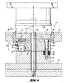
- FIG 3 shows a pressing tool (5) according to the known prior art.
- a press ring (18) is inserted, in which the lower press plate (19), which cooperates with the upper press plate (26), is movable in the vertical direction to eject the compact, not shown, and to change the thickness of the compact .
- the top (6) of the lower press plate (19) forms together with the press ring (18) the shape for the compact.
- Below the lower press plate (19) the adjustment plate (1) is arranged, on the upper side (4) of the press plate (19) with its underside (41). Underneath is the base plate (2), the top (29) of which engages with the bottom (34) of the adjustment plate (1) via compression springs (disc springs).
- Magnets (23) connect the lower press plate (19) and the adjusting plate (1) in order to enable a safe lowering of the lower press plate (19) even if particles of the material to be pressed have reached between the press ring (18) and the lower press plate (19) .
- the lower press plate (19) must be dismantled, by loosening or tightening the screw bolts (16), the angle a that the level formed by the upper end face (4) of the adjustment plate (1) with Longitudinal axis L of the press tool (5) forms to be able to adjust.
- the bolts (16) are screwed into threaded holes (25) in the base plate (2).
- the compression springs (24) in recesses (27) press the setting plate (1) against the screw heads (38).
- the base plate (2) rests on a lifting plate (22) which is guided in columns, not shown. There is a small gap between the press ring (18) and the side edges of the lower press plate (19) to prevent the lower press plate (19) from jamming in the press ring (18) when its inclination is changed via the setting of the adjusting plate (1) .
- the pressing tool (5) according to the invention shown in FIG. 4 is distinguished from the device shown in FIG. 3 by a lifting device (3) which is arranged in the region (17) of the adjusting plate (1) opposite the base plate (2) is not.
- the lifting device (3) is actuated with the master cylinder (8) shown in FIG. (6) via the hose / pipe (7).
- a closable bore (28) serves to vent the lifting device (3).
- the lifting device (3) consists essentially of a piston (30) and a cylinder (31) in which the piston (30) presses against the upper side (29) of the base plate (2).
- the seal between the cylinder (31) and piston (30) is made by sealing rings (32).
- the pressure of the piston (30) creates a wedge gap between the adjusting plate (1) and the base plate (2) at the point marked with an arrow S.
- the angle ⁇ is adjusted, which is formed by the plane formed from the upper side (4) of the adjusting plate (1) and the longitudinal axis L of the pressing tool.
- Magnets (23), only one of which is shown, connect the adjusting plate (1) and the lower press plate.
- Screw bolts (16), of which only one is also shown, serve as in the known pressing tool to connect the adjusting plate (1) and base plate (2), but are not tightened as in the known pressing tools, so that a certain freedom of movement for the Adjustment of the adjustment plate is given.
- the functions of the lifting plate (22) and the upper press plate (26) correspond to the embodiment of the known press tool described in FIG. 3.
- FIG. 5 shows a further embodiment of a pressing tool according to the invention, in which the lifting device (3) is arranged in the region (33) of the base plate (2) opposite the setting plate (1) is not.
- the piston (30) presses against the underside (34) of the adjusting plate (1) and thereby causes a different inclination of the adjusting plate (1) or the lower pressing plate resting thereon.
- this embodiment of the pressing tool corresponds to the embodiment described for FIG. 4.
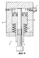
- the master cylinder (8) shown in FIG. 6 consists of a cylinder housing (11) and a piston (10) which can be adjusted in the cylinder housing against the pressure of the spring (9).
- the piston (10) is adjusted by means of a threaded screw (12).
- a connection point (36) is used to connect the hose / pipe (7).
- a closable bore (39) is provided for ventilation.
Landscapes
- Engineering & Computer Science (AREA)
- Mechanical Engineering (AREA)
- Press Drives And Press Lines (AREA)
- Measurement Of The Respiration, Hearing Ability, Form, And Blood Characteristics Of Living Organisms (AREA)
- Treatment Of Fiber Materials (AREA)
- Casting Or Compression Moulding Of Plastics Or The Like (AREA)
Priority Applications (1)
| Application Number | Priority Date | Filing Date | Title |
|---|---|---|---|
| AT85116343T ATE38181T1 (de) | 1984-12-29 | 1985-12-20 | Presswerkzeug. |
Applications Claiming Priority (2)
| Application Number | Priority Date | Filing Date | Title |
|---|---|---|---|
| DE19843447831 DE3447831A1 (de) | 1984-12-29 | 1984-12-29 | Presswerkzeug |
| DE3447831 | 1984-12-29 |
Publications (2)
| Publication Number | Publication Date |
|---|---|
| EP0186878A1 true EP0186878A1 (fr) | 1986-07-09 |
| EP0186878B1 EP0186878B1 (fr) | 1988-10-26 |
Family
ID=6254130
Family Applications (1)
| Application Number | Title | Priority Date | Filing Date |
|---|---|---|---|
| EP85116343A Expired EP0186878B1 (fr) | 1984-12-29 | 1985-12-20 | Outil pour presse |
Country Status (4)
| Country | Link |
|---|---|
| EP (1) | EP0186878B1 (fr) |
| AT (1) | ATE38181T1 (fr) |
| DE (2) | DE3447831A1 (fr) |
| ES (1) | ES8703772A1 (fr) |
Cited By (3)
| Publication number | Priority date | Publication date | Assignee | Title |
|---|---|---|---|---|
| RU2165358C1 (ru) * | 1999-08-03 | 2001-04-20 | Московский государственный технологический университет "СТАНКИН" | Механический пресс для объемной штамповки с секторным исполнительным механизмом |
| CN102794926A (zh) * | 2011-05-25 | 2012-11-28 | 来安县隆华摩擦材料有限公司 | 离合器面片一次性成型模具 |
| CN115703151A (zh) * | 2021-08-10 | 2023-02-17 | 横店集团东磁股份有限公司 | 一种粉末冶金模具 |
Citations (1)
| Publication number | Priority date | Publication date | Assignee | Title |
|---|---|---|---|---|
| DE141650C (fr) * |
Family Cites Families (2)
| Publication number | Priority date | Publication date | Assignee | Title |
|---|---|---|---|---|
| DE291257C (fr) * | ||||
| US4450127A (en) * | 1982-02-23 | 1984-05-22 | Ptx Pentronix, Inc. | Method for compacting powder material with adjustable die and punch assembly |
-
1984
- 1984-12-29 DE DE19843447831 patent/DE3447831A1/de not_active Withdrawn
-
1985
- 1985-12-20 AT AT85116343T patent/ATE38181T1/de active
- 1985-12-20 DE DE8585116343T patent/DE3565796D1/de not_active Expired
- 1985-12-20 EP EP85116343A patent/EP0186878B1/fr not_active Expired
- 1985-12-27 ES ES550478A patent/ES8703772A1/es not_active Expired
Patent Citations (1)
| Publication number | Priority date | Publication date | Assignee | Title |
|---|---|---|---|---|
| DE141650C (fr) * |
Cited By (3)
| Publication number | Priority date | Publication date | Assignee | Title |
|---|---|---|---|---|
| RU2165358C1 (ru) * | 1999-08-03 | 2001-04-20 | Московский государственный технологический университет "СТАНКИН" | Механический пресс для объемной штамповки с секторным исполнительным механизмом |
| CN102794926A (zh) * | 2011-05-25 | 2012-11-28 | 来安县隆华摩擦材料有限公司 | 离合器面片一次性成型模具 |
| CN115703151A (zh) * | 2021-08-10 | 2023-02-17 | 横店集团东磁股份有限公司 | 一种粉末冶金模具 |
Also Published As
| Publication number | Publication date |
|---|---|
| ES550478A0 (es) | 1987-03-01 |
| ATE38181T1 (de) | 1988-11-15 |
| EP0186878B1 (fr) | 1988-10-26 |
| DE3565796D1 (en) | 1988-12-01 |
| ES8703772A1 (es) | 1987-03-01 |
| DE3447831A1 (de) | 1986-07-03 |
Similar Documents
| Publication | Publication Date | Title |
|---|---|---|
| DE2627160C3 (de) | Verfahren zum Herstellen von Tellern o.dgl. mittels einer Presse sowie Presse zur Durchführung des Verfahrens | |
| DE3036533A1 (de) | Presse zur herstellung von formkoerpern aus pulver | |
| EP4076881B1 (fr) | Dispositif pour la fabrication de blocs de béton | |
| DE102016104019B3 (de) | Vorrichtung zur Herstellung von Gussteilen, wie Aluminiumguss, im Druckgießverfahren oder Niederdruckgießverfahren | |
| EP0679503A1 (fr) | Procédé pour fabriquer des pièces moulées à partir de matières pulvérulentes et presse correspondante | |
| EP0556363B1 (fr) | Presse verticale et son procede d'utilisation | |
| DE69423583T2 (de) | Verfahren und Vorrichtung zur Herstellung von Fliesen mit konstanter Dichte und gleichbleibender Dicke und so hergestellte Fliesen | |
| DD228209A5 (de) | Verfahren zur herstellung eines trockengepressten formlings aus trockener, rieselfaehiger formmasse, insbesondere keramischer formmasse | |
| DE102023123181A1 (de) | Vorrichtung zum Herstellen von Formlingen, insbesondere Steinformlinge für Mauerwerksteine und Verfahren zum Ändern eines Formats von herzustellenden Formlingen | |
| EP0186878B1 (fr) | Outil pour presse | |
| DE3926854C2 (de) | Vorrichtung in Keramik-Pressen zum Füllen der Preßform mit pulverförmigem Preßgut | |
| DE2307496C3 (de) | Presse zum Herstellen von Tellern o.dgl. | |
| DE69623878T2 (de) | Vorrichtung geeignet zur Anwendung in einem Pressgerät | |
| DE3928533C2 (de) | Hydraulische Presse, insbesondere für die Baustein-Industrie | |
| DE3527594C2 (fr) | ||
| DE1628955C3 (de) | Verstellbare Distanzeinrichtung an Einetagenpressen zum Pressen unterschiedlich dicker Spanplatten, Faserplatten od.dgl | |
| DE2657993A1 (de) | Presswerkzeug zum herstellen keramischer formlinge aus pulverfoermiger masse | |
| DE1627853C3 (de) | Schrottpreßanlage | |
| DE1627880B2 (de) | Vorrichtung zur Einstellung eines wählbaren Abstandes zwischen einem fest angeordneten und einem beweglichen Pressenholm einer geschlossenen Heizplattenpresse für die Herstellung von Spanplatten od.dgl | |
| DE2630355A1 (de) | Presswerkzeug zum herstellen keramischer formlinge aus pulverfoermiger masse | |
| DE2736287B2 (de) | Vorrichtung zum Herstellen von Betonsteinen od.dgl. | |
| DE1265393B (de) | Geteilte Form fuer eine Presse | |
| DE2537009C2 (de) | Maschine zum Herstellen von Betonformteilen | |
| DE2712489B2 (de) | Vorrichtung zum Einfüllen und Verdichten des Formsandes bei der Herstellung von Sandformen für Gießereizwecke | |
| DE4401506C1 (de) | Lagerung einer Trommel in einer Presse für keramische Massen, insbesondere für die Herstellung von Dachziegeln |
Legal Events
| Date | Code | Title | Description |
|---|---|---|---|
| PUAI | Public reference made under article 153(3) epc to a published international application that has entered the european phase |
Free format text: ORIGINAL CODE: 0009012 |
|
| AK | Designated contracting states |
Kind code of ref document: A1 Designated state(s): AT BE CH DE FR GB IT LI LU NL SE |
|
| 17P | Request for examination filed |
Effective date: 19860716 |
|
| 17Q | First examination report despatched |
Effective date: 19870604 |
|
| GRAA | (expected) grant |
Free format text: ORIGINAL CODE: 0009210 |
|
| AK | Designated contracting states |
Kind code of ref document: B1 Designated state(s): AT BE CH DE FR GB IT LI LU NL SE |
|
| REF | Corresponds to: |
Ref document number: 38181 Country of ref document: AT Date of ref document: 19881115 Kind code of ref document: T |
|
| ITF | It: translation for a ep patent filed | ||
| REF | Corresponds to: |
Ref document number: 3565796 Country of ref document: DE Date of ref document: 19881201 |
|
| ET | Fr: translation filed | ||
| PG25 | Lapsed in a contracting state [announced via postgrant information from national office to epo] |
Ref country code: LU Free format text: LAPSE BECAUSE OF NON-PAYMENT OF DUE FEES Effective date: 19881231 |
|
| GBT | Gb: translation of ep patent filed (gb section 77(6)(a)/1977) | ||
| PGFP | Annual fee paid to national office [announced via postgrant information from national office to epo] |
Ref country code: LU Payment date: 19890308 Year of fee payment: 5 |
|
| PLBE | No opposition filed within time limit |
Free format text: ORIGINAL CODE: 0009261 |
|
| STAA | Information on the status of an ep patent application or granted ep patent |
Free format text: STATUS: NO OPPOSITION FILED WITHIN TIME LIMIT |
|
| 26N | No opposition filed | ||
| PGFP | Annual fee paid to national office [announced via postgrant information from national office to epo] |
Ref country code: DE Payment date: 19891130 Year of fee payment: 5 |
|
| PGFP | Annual fee paid to national office [announced via postgrant information from national office to epo] |
Ref country code: BE Payment date: 19891219 Year of fee payment: 5 |
|
| PGFP | Annual fee paid to national office [announced via postgrant information from national office to epo] |
Ref country code: FR Payment date: 19891221 Year of fee payment: 5 |
|
| PGFP | Annual fee paid to national office [announced via postgrant information from national office to epo] |
Ref country code: AT Payment date: 19891222 Year of fee payment: 5 |
|
| PGFP | Annual fee paid to national office [announced via postgrant information from national office to epo] |
Ref country code: SE Payment date: 19891227 Year of fee payment: 5 |
|
| ITTA | It: last paid annual fee | ||
| PGFP | Annual fee paid to national office [announced via postgrant information from national office to epo] |
Ref country code: NL Payment date: 19891231 Year of fee payment: 5 Ref country code: GB Payment date: 19891231 Year of fee payment: 5 |
|
| PGFP | Annual fee paid to national office [announced via postgrant information from national office to epo] |
Ref country code: CH Payment date: 19900119 Year of fee payment: 5 |
|
| PG25 | Lapsed in a contracting state [announced via postgrant information from national office to epo] |
Ref country code: GB Effective date: 19901220 Ref country code: AT Effective date: 19901220 |
|
| PG25 | Lapsed in a contracting state [announced via postgrant information from national office to epo] |
Ref country code: SE Effective date: 19901221 |
|
| PG25 | Lapsed in a contracting state [announced via postgrant information from national office to epo] |
Ref country code: LI Effective date: 19901231 Ref country code: CH Effective date: 19901231 Ref country code: BE Effective date: 19901231 |
|
| BERE | Be: lapsed |
Owner name: FELDMUHLE A.G. Effective date: 19901231 |
|
| PG25 | Lapsed in a contracting state [announced via postgrant information from national office to epo] |
Ref country code: NL Effective date: 19910701 |
|
| GBPC | Gb: european patent ceased through non-payment of renewal fee | ||
| NLV4 | Nl: lapsed or anulled due to non-payment of the annual fee | ||
| PG25 | Lapsed in a contracting state [announced via postgrant information from national office to epo] |
Ref country code: FR Effective date: 19910830 |
|
| REG | Reference to a national code |
Ref country code: CH Ref legal event code: PL |
|
| PG25 | Lapsed in a contracting state [announced via postgrant information from national office to epo] |
Ref country code: DE Effective date: 19910903 |
|
| REG | Reference to a national code |
Ref country code: FR Ref legal event code: ST |
|
| EUG | Se: european patent has lapsed |
Ref document number: 85116343.6 Effective date: 19910910 |