EP0186909B1 - Dispositif pour ajuster la longueur d'outil des machines à cintrer - Google Patents
Dispositif pour ajuster la longueur d'outil des machines à cintrer Download PDFInfo
- Publication number
- EP0186909B1 EP0186909B1 EP85116595A EP85116595A EP0186909B1 EP 0186909 B1 EP0186909 B1 EP 0186909B1 EP 85116595 A EP85116595 A EP 85116595A EP 85116595 A EP85116595 A EP 85116595A EP 0186909 B1 EP0186909 B1 EP 0186909B1
- Authority
- EP
- European Patent Office
- Prior art keywords
- die segments
- die
- segments
- corner
- central
- Prior art date
- Legal status (The legal status is an assumption and is not a legal conclusion. Google has not performed a legal analysis and makes no representation as to the accuracy of the status listed.)
- Expired - Lifetime
Links
Images


Classifications
-
- B—PERFORMING OPERATIONS; TRANSPORTING
- B21—MECHANICAL METAL-WORKING WITHOUT ESSENTIALLY REMOVING MATERIAL; PUNCHING METAL
- B21D—WORKING OR PROCESSING OF SHEET METAL OR METAL TUBES, RODS OR PROFILES WITHOUT ESSENTIALLY REMOVING MATERIAL; PUNCHING METAL
- B21D5/00—Bending sheet metal along straight lines, e.g. to form simple curves
- B21D5/04—Bending sheet metal along straight lines, e.g. to form simple curves on brakes making use of clamping means on one side of the work
- B21D5/042—With a rotational movement of the bending blade
-
- B—PERFORMING OPERATIONS; TRANSPORTING
- B21—MECHANICAL METAL-WORKING WITHOUT ESSENTIALLY REMOVING MATERIAL; PUNCHING METAL
- B21D—WORKING OR PROCESSING OF SHEET METAL OR METAL TUBES, RODS OR PROFILES WITHOUT ESSENTIALLY REMOVING MATERIAL; PUNCHING METAL
- B21D5/00—Bending sheet metal along straight lines, e.g. to form simple curves
- B21D5/02—Bending sheet metal along straight lines, e.g. to form simple curves on press brakes without making use of clamping means
- B21D5/0209—Tools therefor
- B21D5/0218—Length adjustment of the punch
-
- B—PERFORMING OPERATIONS; TRANSPORTING
- B21—MECHANICAL METAL-WORKING WITHOUT ESSENTIALLY REMOVING MATERIAL; PUNCHING METAL
- B21D—WORKING OR PROCESSING OF SHEET METAL OR METAL TUBES, RODS OR PROFILES WITHOUT ESSENTIALLY REMOVING MATERIAL; PUNCHING METAL
- B21D5/00—Bending sheet metal along straight lines, e.g. to form simple curves
- B21D5/04—Bending sheet metal along straight lines, e.g. to form simple curves on brakes making use of clamping means on one side of the work
- B21D5/047—Length adjustment of the clamping means
Definitions
- This invention relates to an apparatus for adjusting the tool length of a bending machine according to the prior art portion of claim 1, i.e. wherein the effective length of the upper tool can be changed to the dssired bending length according to the bending width of a sheet metal plate.
- Rectangular sheet metal plates having the edges at the four sides bent at least one or two times so as to have L- or U-rims are used for cabinets, display cases, refrigerators, freezers, air conditioners, computer units, various office machines, etc.
- wiping benders, folding machines or press brakes are used which bend each side edge of the sheet metal previously cut into a quadrilateral.
- the edge of one short side of the sheet metal is bent by two steps (short side bending) and then, after the sheet metal is turned 180° on a handling table, the edge of the other short side is bent.
- the sheet metal is turned 90° and the edge of one long side is bent (long side bending) by a clamp die or punch set to the bending width adjusted to the inside of the short side bending. Further, the sheet metal is turned 180° and the other long side is bent so that the rectangular metal plate having the four sides bent in the U-shaped form is obtained from the first step bending and the following second step bending.
- auxiliary die segments can be inverted, i.e. pivoted into or out of alignment of the active die segments. Longitudinally offsetting the lateral die segments results in any one of them being used as corner die segments, which is not always satisfactory since the corner die segments are sometimes required to present special performance, particularly in case of a U-rim.
- a special corner die segment is to be used which can be one comprising an openable die portion (or rotary die portion) mounted at the upper corner die segements by the use of a pin. And to pivot this openable die portion without any troubles, a clearance is provided in an edge portion of the upper corner die body to avoid the contact with the pivotal part of the openable die portion.
- this clearance provides a cut-out portion of the edge line of the upper die, the bending line of the sheet metal has irregularites on the clearance portion so that an accurate being form cannot be obtained.
- An object of the present invention is to provide an apparatus for adjusting the tool length of a bending machine in which the tool length can be changed easily and quickly, leaving the possibility of special corner constructions of the upper die.
- This can be realized by the invention characterized in claim 1.
- the invention characterized in claim 1.
- the construction of claim 6 which provides an upper bending die in which the edge lines of the upper corner die segment body and the openable die portion are interconnected continuously.
- the tool lenth can be freely adjusted between the maximum and the minimum by 100 mm or 5 mm pitch.
- the upper die length has each 2.5 mm pitch at both ends, assuming each auxiliary die is 5 mm thick, so that the change in the work length within said extent can be substantially coped with.
- the operation of said drive mechanism, reversing mechanism, etc. permits the bending operation of differently sized sheet metal to be flexibly carried out by employing the NC control.
- the upper tool corners are always constituted by the upper corner die segments so that these can be constructed according to any special desire.
- the upper corner die segments at both ends of the upper die group are improved to make the bending operation of the four sides of sheet metal very easy and fast.
- the present invention can be applied not only to press brakes, but also to bending machines such as folding machines, wiping benders, etc.
- reference numeral 10 designates left and right frames
- 11 is a front plate stretched in front of the frames
- 12 press cylinders mounted on the upper ends of the frames
- 13 a ram moved vertically to the front plate 11 by the actuation of the press cylinders
- Reference numeral 14 designates a bed on the upper surface of the front plate, 15 a slide member provided on the bed 14, 16 a lower die, 17 a V-shaped groove formed in the lower die 16,18 a back gauge, 19 a T-shaped groove formed in the lower end of the ram and 20 a group of upper die segments (punch).
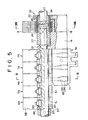
- the group of upper die segments 20 are constituted from a pair of left and right central die segments 1A, 1B slidable longitudinally of the tool length, a pair of left and right upper corner die segments 7A, 7B slidable similarly, a plurality of upper slit, lateral die segments 2A to 6A and 2B to 6B which are inserted between the central die segments and the upper corner die segments and a plurality of thin upper auxiliary die segments 8 which are inserted between the left and right central die segments.
- Said upper lateral die segments and the upper auxiliary die segments cannot slide and are supported by the shaft to be inverted rearwardly, i.e.
- the lateral die segments and the auxiliary die segments each have two stable positions, one of which is the working position wherein the respective segment is in alignment with the central die segments, and the other one is the inverted position wherein the respective segment is spaced from alignment with the central die segments.
- the central die segments 1A, 1 B have the upper portions inserted into a groove 19 in the lower end of the ram to be slidably supported thereby.
- Brackets 21, 22 extend to the back of the central die segments to hold the thin auxiliary die segments 8 group and spline cylinders 23, 24 having a split respectively, as will be later described.
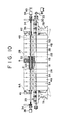
- the left and right upper corner die segments 7A, 7B have the upper portions inserted into the groove 19, while being supported slidably by a drive mechanism 30 (Fig. 10-13). That is, each upper corner die segment is formed in the interior with a female thread 31 (Fig.
- each upper corner die segment 7A, 7B has an openable die segment portion 72 pivotably connected to the upper corner die segment body; the constitution and features of the openable die segment portion will be described later.
- a pair of left and right shafts 35, 36 are disposed on the back of said central die segments 1A, 1B and provided near the ends with a reversing drive unit 34 such as a rack-pinion or gear mechanism so as to be supportably rotated about 180°.
- the shafts 35, 36 are provided at the ends with cylinders 38, 39 operated when the number of the thin auxiliary die segments 8 to be reversed is selected, and further at an end of one cylinder with a shift cylinder 40 for centering the whole upper die segment group when an odd number of the upper lateral die segments are used.
- cylinders 41, 42 for fastening the upper lateral die segments group in the inverted, ascended state.
- the upper lateral die segments 2A, 2B-6A, 6B are constituted respectively from body portions 57 and die segment portions 58, and the shafts 35,36 are inserted into a hole 45 laterally provided in the body portions 57 and are provided with a longitudinal key way 46 on a portion supporting the upper lateral die segments (Figs. 5 and 10).
- a movable body 51 urged normally to advance by a spring 48.
- a wedge 50 is provided which is bent and inserted into the key way 46 in said shafts 35, 36 from the upper end of this movable body 51.
- the upper corner die segments 7A, 7B have a tool length of integral times that of the upper lateral die segments (two times in the drawing), and as shown in Figs. 5 and 10, the upper portions thereof each have such tool length plus the length of one upper lateral die segment (one corresponding to three upper lateral die segments in the drawing).
- the upper corner die segments are each provided three wedge releasing mechanisms 55 (Fig. 4, 5) each consisting of a piston 53 and a cylinder 54 to release the wedges 50 of the adjacent upper lateral die segments, for maintaining said upper lateral die segments in the inverted positions while turning the other ones into the non-inverted condition of Fig. 2 by pivoting the shafts 35, 36.
- the thin auxiliary die segments 8 are provided respectively with a spline hole 26 meshing with a spline cylinder and supported on a mechanism 25 for selecting the number of the upper lateral die segments to be inverted.
- This mechanism 25 consists of the spline cylinders 23, 24 having splits near the position in which the shafts 35, 36 are butted against each other, and the cylinders 38, 39 for shifting each shaft outward.
- the spline cylinder 23 is secured fixedly to an end of the shaft 36 by the use of a pin 27 to invert the auxiliary die segments. 8 engaging the corresponding spline cylinder 23 in rotating the shaft.
- the other spline cylinder 24 is secured fixedly to the bracket 22 for one central die segment to support the auxiliary upper die segments 8 engaging the corresponding spline cylinder 24 under the non-inverted condition.
- the upper corner die segments are arranged left and right of the upper lateral die segment row and moved in the opposite directions to each other by the left and right reversely threaded rod 32.
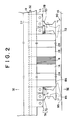
- the upper corner die segments 7A, 7B consist of main bodies 71 having the height equal about a half of that of the adjacent upper lateral die segments, and the openable die segment portions 72 mounted on the lower part of each main body 71.
- a T-shaped part formed on the upper portion of the main body 71 is inserted into the T-shaped groove 19 in the lower portion of the ram 13 and is screwed onto the screw rod 32 extending through the T-shaped groove 19.
- Said openable die segment portion 72 is mounted removably on the main body 71 through a link 75 provided on the lower portion of the main body 71. That is, a bracket 76 is suspended from the lower corner of the main body 71 at the side contacting the upper lateral die segment, and a pin 77 extends through this bracket 76 in the direction orthogonal to the bending line to mount said link 75, on the end of which is supported the openable die segment portion 72 by the use of a pin 78 (Figs. 9, 15). As shown in Fig. 9, the openable die segment portion 72 has a recess 79 to avoid the interference with a rise 95 at the work end side as viewed from the front and is formed with a cavity 80 at the side adjacent the upper lateral die segment.
- the cavity 80 has a side oblique surface 82 abutting against an end face 81 of the adjacent upper lateral die segment upon withdrawing the die segment upwardly, preventing the openable die segment portion 72 from further pivoting. Furthermore, a side oblique surface 83 extending from the lower end of the side oblique surface 82 toward the edge of said upper die segment portion is designed so as to form a vertical flat surface 84 in the lower end of said side oblique surface, surface 84 contacting closely said end face 81 of the upper lateral die segment in the non-opened condition of the die segment portion 72.
- Fig. 10 shows the tool length of 850 mm using all die segments except for the upper auxiliary die segments 8
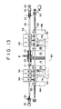
- Fig. 11 shows the tool length of 350 mm with the central and corner die segments only.
- the rotary unit 33 is driven by an NC control to rotate the screw rod 32 and move left and right the corner die segments 7A, 7B each by 12.5 mm, so as to be aligned with the lateral die segments 3A to 5A and 3B to 5B, respectively.
- the three pistons 53 (Fig. 4, 6) of the wedge releasing mechanisms 55 in the upper corner die segments 7A, 7B are moved to hit and offset the respective movable bodies 51 of the wedges 50 for the upper lateral die segments 3A to 5A, 3B to 5B.
- the cylinder 54 is operated to move left in Fig.
- the ram 13 is lowered to bend the proximity of the edge of the sheet metal 90 and to bend the long and short sides for providing a completed product as shown in Fig. 18.
- the inverting drive unit 34 is driven in the opposite direction to the previous one to invert simultaneously the five upper auxiliary die segments 8 inserted beween the central die segments 1A, 1B and the upper lateral die segments 2A, 2B left wedged in the shafts 35, 36 to the condition shown in Fig. 12.
- the upper corner die segments 7A, 7B before and after the bending are operated as follows: As shown in Figs. 2 and 9, until the openable die segment 7A, 7B portion 72 of each upper corner die segment descends from the ram lifting position and touches the sheet metal 90, it is supported and brought down inwardly slanted by the link 75 as shown by the chain line in said drawings. When the ram 13 is lowered in such state, it does not abut against the rise 95 of the sheet metal. When the ram 13 is then further lowered, the openable die segment portion 72 touches the work before the upper lateral die segments 2A, 2B-6A, 6B touch same, and begins to pivot clockwise in Fig. 9.
- the edges 86 of the upper lateral die segments touch the work, as shown by the solid line in the same drawing, the flat surface 84 of the openable die segment contact closely the end face 81 of the adjacent upper lateral die segment 6A or 6B, while the edges 85, 86 are arranged on the same line. Since the edge line does not have any gaps, it can withstand a large load so that the sheet metal can be bent along a clear even bending line by pressing it under such condition.
- the rod 88 guided by the hole 89 is regulated to descend for example 3 to 5 mm vertically at the beginning of the pivoting. Since the flat surface 84 of the openable die segment portion is moved out of the end face 81 by that vertical descend, the openable die segment portion is thereafter pivoted about the pin 77 and the side oblique surface 82 abuts against the end face of the upper lateral die segment and stops so that it can return to the condition shown by the chain line and be withdrawn without interfering with the rise 95 of the work.
- Figs. 14 and 15 are respectively sectional and front views showing a modification of the upper corner die segment.
- a main body 101 is provided on the lower corner with the backet 76 for supporting the goose-neck-shaped openable die segment portion 102 through a link 103.
- An arm 104 is provided upward from the pivotal fulcrum side of the link 103, while an air cylinder 105 parallel to the edge line is provided in the main body 101 and an end of a piston 106 inserted into the cylinder 105 is disposed to abut against an end of said arm 104.
- presurized air is supplied from an approach port 107 of the cylinder to move the piston 106 right, hold the link 103 horizontally and make the openable die segment portion 102 contact closely the main body 101 and the upper lateral die segment.
- air in the cylinder 105 is vented to slant the openable die segment 102 by its own weight and avoid the interference with the rise 95 of the sheet metal similarly to the previously mentioned embodiment.
- the edge line is formed without any gaps between the openable die segment portion and the adjacent upper lateral die segments.
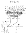
- Fig. 16 shows a further modification of the upper corner die segment applied to a folding machine according to the present invention.
- This upper corner die segment is almost the same as that in Figs. 14 and 15.
- the die itself applies to a clamp die segment 110 of the folding machine which is opposed to a lower die 111 and lowered by the press cylinder of the ram to clamp the sheet metal 90 and bend the sheet metal edge by pivoting a rotary die segment 112 in the direction of arrow.
- all of the upper lateral die segments, central die segments and thin upper die segments have the same shape as the clamp die segment 110, the illustration of them is omitted.
- the operational effect of the upper corner die segment is the same as that of the before-mentioned embodiment.
- the apparatus for adjusting the tool length of a bending machine since the apparatus for adjusting the tool length of a bending machine according to the present invention has the invertible upper lateral die segments together with the invertible thin upper auxiliary die segments for fine adjustment of the tool length, it can sufficiently cope with the change of the sheet metal length and easily accurately carry out the working to bend four sides.
Landscapes
- Engineering & Computer Science (AREA)
- Mechanical Engineering (AREA)
- Bending Of Plates, Rods, And Pipes (AREA)
- Shaping Of Tube Ends By Bending Or Straightening (AREA)
- Braking Arrangements (AREA)
Claims (7)
Priority Applications (2)
| Application Number | Priority Date | Filing Date | Title |
|---|---|---|---|
| AT88120283T ATE88927T1 (de) | 1984-12-29 | 1985-12-27 | Abkantpresse. |
| AT85116595T ATE54078T1 (de) | 1984-12-29 | 1985-12-27 | Vorrichtung zur anpassung der werkzeuglaenge bei biegemaschinen. |
Applications Claiming Priority (4)
| Application Number | Priority Date | Filing Date | Title |
|---|---|---|---|
| JP59281519A JPS61159224A (ja) | 1984-12-29 | 1984-12-29 | プレスブレ−キの型長さ変換装置 |
| JP281519/84 | 1984-12-29 | ||
| JP279224/85 | 1985-12-13 | ||
| JP60279224A JPS62142025A (ja) | 1985-12-13 | 1985-12-13 | 折曲げ機の隅部上型 |
Related Child Applications (1)
| Application Number | Title | Priority Date | Filing Date |
|---|---|---|---|
| EP88120283.2 Division-Into | 1988-12-05 |
Publications (3)
| Publication Number | Publication Date |
|---|---|
| EP0186909A2 EP0186909A2 (fr) | 1986-07-09 |
| EP0186909A3 EP0186909A3 (en) | 1987-03-25 |
| EP0186909B1 true EP0186909B1 (fr) | 1990-06-27 |
Family
ID=26553227
Family Applications (2)
| Application Number | Title | Priority Date | Filing Date |
|---|---|---|---|
| EP85116595A Expired - Lifetime EP0186909B1 (fr) | 1984-12-29 | 1985-12-27 | Dispositif pour ajuster la longueur d'outil des machines à cintrer |
| EP88120283A Expired - Lifetime EP0310145B1 (fr) | 1984-12-29 | 1985-12-27 | Machine à cintrer |
Family Applications After (1)
| Application Number | Title | Priority Date | Filing Date |
|---|---|---|---|
| EP88120283A Expired - Lifetime EP0310145B1 (fr) | 1984-12-29 | 1985-12-27 | Machine à cintrer |
Country Status (4)
| Country | Link |
|---|---|
| EP (2) | EP0186909B1 (fr) |
| KR (1) | KR890004036B1 (fr) |
| AT (1) | ATE54078T1 (fr) |
| DE (2) | DE3578390D1 (fr) |
Cited By (1)
| Publication number | Priority date | Publication date | Assignee | Title |
|---|---|---|---|---|
| CN105992658A (zh) * | 2014-02-10 | 2016-10-05 | 萨尔瓦尼尼意大利股份公司 | 金属板片折弯机 |
Families Citing this family (17)
| Publication number | Priority date | Publication date | Assignee | Title |
|---|---|---|---|---|
| AT385689B (de) * | 1986-08-14 | 1988-05-10 | Voest Alpine Ag | Vorrichtung zum abkanten von blechzuschnitten |
| AT385688B (de) * | 1986-08-14 | 1988-05-10 | Voest Alpine Ag | Vorrichtung zum abkanten von blechzuschnitten |
| AT385690B (de) * | 1986-08-28 | 1988-05-10 | Voest Alpine Ag | Vorrichtung zum abkanten von blechzuschnitten |
| IT1201126B (it) * | 1987-01-09 | 1989-01-27 | Salvagnini Transferica Spa | Macchina piegatrice per la produzione di pannelli in lamiera rettangolari a partire da fogli piani di lamiera |
| IT1238060B (it) * | 1990-02-09 | 1993-06-26 | Salvagnini Transferica Spa Ora | Gruppo di piegatura per macchina piegatrice di fogli di lamiera |
| ES2063671B1 (es) * | 1992-12-24 | 1996-12-01 | Goiti S Coop Ltda | Dispositivo automatico de adaptacion longitudinal del pisador en maquinas plegadoras-paneladoras. |
| EP0713734B1 (fr) * | 1994-11-24 | 2002-02-20 | AMADA COMPANY, Ltd. | Dispositif pour presser des pièces à usiner pour un ensemble variable à étapes présélectionnées pour presses plieuses |
| DE19636463C2 (de) * | 1996-09-07 | 1998-07-02 | Eht Werkzeugmaschinen Gmbh | Blechbearbeitungsmaschine für plattenförmige Werkstücke mit einem in einzelne Segmente unterteilten Niederhalter |
| IE960695A1 (en) * | 1996-10-01 | 1998-04-08 | Rainforest R & D Limited | An apparatus and a method for bending a component |
| FR2952580B1 (fr) * | 2009-11-18 | 2012-02-24 | Peugeot Citroen Automobiles Sa | Outil d'emboutissage pour relever un bord d'une tole non demoule apres relevage |
| DE102014116386A1 (de) * | 2014-11-10 | 2016-05-12 | Trumpf Maschinen Austria Gmbh & Co.Kg. | Biegepresse und Beschickungsvorrichtung für eine Biegepresse |
| AT516043B1 (de) * | 2014-11-12 | 2016-02-15 | Trumpf Maschinen Austria Gmbh | Biegepresse und Beschickungsvorrichtung für eine Biegepresse |
| CN106734396A (zh) * | 2015-09-17 | 2017-05-31 | 佛山高富中石油燃料沥青有限责任公司 | 改进的可调节的金属板材弯折装置 |
| AT517597B1 (de) * | 2016-03-07 | 2017-03-15 | Trumpf Maschinen Austria Gmbh & Co Kg | Verfahren zum gleichzeitigen Verschieben von zumindest zwei, in einer Schiene einer Werkzeughalterung gehaltenen Biegewerkzeugen |
| CN108144994A (zh) * | 2016-12-06 | 2018-06-12 | 湖南家吉盈泰门业有限公司 | 一种带前置调节机构的手动折弯机 |
| CN108637100A (zh) * | 2018-07-14 | 2018-10-12 | 青岛城之美创意科技股份有限公司 | 一种模块化万能v型折弯底模 |
| CN116673409B (zh) * | 2023-06-16 | 2026-02-06 | 上海柘中电气有限公司 | 一种配电柜折弯生产过程中的辅助支撑装置 |
Citations (1)
| Publication number | Priority date | Publication date | Assignee | Title |
|---|---|---|---|---|
| EP0105091A2 (fr) * | 1982-09-08 | 1984-04-11 | Maru Kikai Kogyo Co., Inc. | Dispositif pour modifier la longueur de l'outil dans une machine à plier les panneaux |
Family Cites Families (3)
| Publication number | Priority date | Publication date | Assignee | Title |
|---|---|---|---|---|
| AT199032B (de) * | 1956-12-06 | 1958-08-11 | Max Abt | Einrichtung zum Biegen von Blechen od. dgl. |
| AT304996B (de) * | 1971-01-19 | 1973-02-12 | Haemmerle Ag Maschf | Biegebearbeitungseinrichtung |
| JPS52759A (en) * | 1975-06-24 | 1977-01-06 | Tadashi Amano | Freely stretchable metal mold |
-
1985
- 1985-12-27 AT AT85116595T patent/ATE54078T1/de active
- 1985-12-27 EP EP85116595A patent/EP0186909B1/fr not_active Expired - Lifetime
- 1985-12-27 DE DE8585116595T patent/DE3578390D1/de not_active Expired - Fee Related
- 1985-12-27 EP EP88120283A patent/EP0310145B1/fr not_active Expired - Lifetime
- 1985-12-27 DE DE88120283T patent/DE3587327T2/de not_active Expired - Fee Related
- 1985-12-30 KR KR1019850009980A patent/KR890004036B1/ko not_active Expired
Patent Citations (1)
| Publication number | Priority date | Publication date | Assignee | Title |
|---|---|---|---|---|
| EP0105091A2 (fr) * | 1982-09-08 | 1984-04-11 | Maru Kikai Kogyo Co., Inc. | Dispositif pour modifier la longueur de l'outil dans une machine à plier les panneaux |
Cited By (2)
| Publication number | Priority date | Publication date | Assignee | Title |
|---|---|---|---|---|
| CN105992658A (zh) * | 2014-02-10 | 2016-10-05 | 萨尔瓦尼尼意大利股份公司 | 金属板片折弯机 |
| CN105992658B (zh) * | 2014-02-10 | 2018-10-30 | 萨尔瓦尼尼意大利股份公司 | 金属板片折弯机 |
Also Published As
| Publication number | Publication date |
|---|---|
| KR890004036B1 (ko) | 1989-10-18 |
| EP0186909A3 (en) | 1987-03-25 |
| DE3587327D1 (de) | 1993-06-09 |
| EP0310145B1 (fr) | 1993-05-05 |
| EP0310145A2 (fr) | 1989-04-05 |
| EP0186909A2 (fr) | 1986-07-09 |
| DE3578390D1 (de) | 1990-08-02 |
| ATE54078T1 (de) | 1990-07-15 |
| EP0310145A3 (en) | 1989-12-06 |
| KR860004665A (ko) | 1986-07-11 |
| DE3587327T2 (de) | 1993-10-07 |
Similar Documents
| Publication | Publication Date | Title |
|---|---|---|
| US4660402A (en) | Apparatus for adjusting tool length of bending machine | |
| EP0186909B1 (fr) | Dispositif pour ajuster la longueur d'outil des machines à cintrer | |
| KR890001369B1 (ko) | 패널 성형기계의 공구길이 조정장치 | |
| JPS63119931A (ja) | プレスブレ−キの上型交換装置 | |
| US4043165A (en) | Three-point, air-bending sheet metal bender | |
| US3788215A (en) | Printer with screen frame lift and squeegee support pivot means | |
| US4768367A (en) | Bending brake | |
| JPS6116203B2 (fr) | ||
| KR101061239B1 (ko) | 롤 포밍 스트립 절단장치 | |
| JPS64132B2 (fr) | ||
| EP0641265B1 (fr) | Machine a dresser | |
| IT8149917A1 (it) | Apparecchio di taglio e tranciatura di materiali in foglio in particolare lamiere metalliche | |
| US5001922A (en) | Quick change tooling for press machine | |
| JP2632919B2 (ja) | 板材折曲げ加工機 | |
| JPS61206525A (ja) | 折曲げ機 | |
| JP3737859B2 (ja) | 曲げ加工プレス | |
| JP3964987B2 (ja) | ロールフォーミング装置 | |
| JPH0248087Y2 (fr) | ||
| JPH03180215A (ja) | 折曲げ加工機 | |
| CN118371575B (zh) | 一种装甲门门板剪冲设备 | |
| JP2632918B2 (ja) | 板材折曲げ加工機 | |
| JPS62134119A (ja) | ロ−ル曲げ加工装置 | |
| JPH0744328Y2 (ja) | 折曲げ機械のパンチ自動交換装置 | |
| JP2521741B2 (ja) | 折曲げ機 | |
| JPH02160121A (ja) | 枠材製造用折曲げ装置 |
Legal Events
| Date | Code | Title | Description |
|---|---|---|---|
| PUAI | Public reference made under article 153(3) epc to a published international application that has entered the european phase |
Free format text: ORIGINAL CODE: 0009012 |
|
| AK | Designated contracting states |
Kind code of ref document: A2 Designated state(s): AT CH DE FR GB IT LI |
|
| 17P | Request for examination filed |
Effective date: 19860801 |
|
| PUAL | Search report despatched |
Free format text: ORIGINAL CODE: 0009013 |
|
| AK | Designated contracting states |
Kind code of ref document: A3 Designated state(s): AT CH DE FR GB IT LI |
|
| 17Q | First examination report despatched |
Effective date: 19881004 |
|
| GRAA | (expected) grant |
Free format text: ORIGINAL CODE: 0009210 |
|
| AK | Designated contracting states |
Kind code of ref document: B1 Designated state(s): AT CH DE FR GB IT LI |
|
| REF | Corresponds to: |
Ref document number: 54078 Country of ref document: AT Date of ref document: 19900715 Kind code of ref document: T |
|
| XX | Miscellaneous (additional remarks) |
Free format text: TEILANMELDUNG 88120283.2 EINGEREICHT AM 27/12/85. |
|
| ITF | It: translation for a ep patent filed | ||
| REF | Corresponds to: |
Ref document number: 3578390 Country of ref document: DE Date of ref document: 19900802 |
|
| ET | Fr: translation filed | ||
| ITTA | It: last paid annual fee | ||
| PLBE | No opposition filed within time limit |
Free format text: ORIGINAL CODE: 0009261 |
|
| STAA | Information on the status of an ep patent application or granted ep patent |
Free format text: STATUS: NO OPPOSITION FILED WITHIN TIME LIMIT |
|
| 26N | No opposition filed | ||
| REG | Reference to a national code |
Ref country code: CH Ref legal event code: PUE Owner name: MARU KIKAI KOGYO CO., INC. TRANSFER- MURATA KIKAI Ref country code: CH Ref legal event code: NV Representative=s name: RIEDERER HASLER & PARTNER PATENTANWAELTE AG |
|
| REG | Reference to a national code |
Ref country code: GB Ref legal event code: 732E |
|
| REG | Reference to a national code |
Ref country code: FR Ref legal event code: TP |
|
| PGFP | Annual fee paid to national office [announced via postgrant information from national office to epo] |
Ref country code: CH Payment date: 20001201 Year of fee payment: 16 |
|
| PGFP | Annual fee paid to national office [announced via postgrant information from national office to epo] |
Ref country code: GB Payment date: 20001211 Year of fee payment: 16 |
|
| PGFP | Annual fee paid to national office [announced via postgrant information from national office to epo] |
Ref country code: DE Payment date: 20001219 Year of fee payment: 16 |
|
| PGFP | Annual fee paid to national office [announced via postgrant information from national office to epo] |
Ref country code: AT Payment date: 20001222 Year of fee payment: 16 |
|
| PGFP | Annual fee paid to national office [announced via postgrant information from national office to epo] |
Ref country code: FR Payment date: 20001229 Year of fee payment: 16 |
|
| PG25 | Lapsed in a contracting state [announced via postgrant information from national office to epo] |
Ref country code: GB Free format text: LAPSE BECAUSE OF NON-PAYMENT OF DUE FEES Effective date: 20011227 Ref country code: AT Free format text: LAPSE BECAUSE OF NON-PAYMENT OF DUE FEES Effective date: 20011227 |
|
| PG25 | Lapsed in a contracting state [announced via postgrant information from national office to epo] |
Ref country code: LI Free format text: LAPSE BECAUSE OF NON-PAYMENT OF DUE FEES Effective date: 20011231 Ref country code: CH Free format text: LAPSE BECAUSE OF NON-PAYMENT OF DUE FEES Effective date: 20011231 |
|
| REG | Reference to a national code |
Ref country code: GB Ref legal event code: IF02 |
|
| PG25 | Lapsed in a contracting state [announced via postgrant information from national office to epo] |
Ref country code: DE Free format text: LAPSE BECAUSE OF NON-PAYMENT OF DUE FEES Effective date: 20020702 |
|
| GBPC | Gb: european patent ceased through non-payment of renewal fee |
Effective date: 20011227 |
|
| REG | Reference to a national code |
Ref country code: CH Ref legal event code: PL |
|
| PG25 | Lapsed in a contracting state [announced via postgrant information from national office to epo] |
Ref country code: FR Free format text: LAPSE BECAUSE OF NON-PAYMENT OF DUE FEES Effective date: 20020830 |
|
| REG | Reference to a national code |
Ref country code: FR Ref legal event code: ST |