EP0186941A1 - Réseaux locaux interconnectés de façon matricielle - Google Patents
Réseaux locaux interconnectés de façon matricielle Download PDFInfo
- Publication number
- EP0186941A1 EP0186941A1 EP85307278A EP85307278A EP0186941A1 EP 0186941 A1 EP0186941 A1 EP 0186941A1 EP 85307278 A EP85307278 A EP 85307278A EP 85307278 A EP85307278 A EP 85307278A EP 0186941 A1 EP0186941 A1 EP 0186941A1
- Authority
- EP
- European Patent Office
- Prior art keywords
- local area
- lan
- matrix
- call sign
- area networks
- Prior art date
- Legal status (The legal status is an assumption and is not a legal conclusion. Google has not performed a legal analysis and makes no representation as to the accuracy of the status listed.)
- Ceased
Links
- 239000011159 matrix material Substances 0.000 title claims abstract description 35
- 230000003287 optical effect Effects 0.000 claims abstract description 4
- 239000000835 fiber Substances 0.000 claims abstract 2
- 238000012544 monitoring process Methods 0.000 claims description 2
- 230000005540 biological transmission Effects 0.000 description 2
- 239000013307 optical fiber Substances 0.000 description 2
- XUIMIQQOPSSXEZ-UHFFFAOYSA-N Silicon Chemical compound [Si] XUIMIQQOPSSXEZ-UHFFFAOYSA-N 0.000 description 1
- 238000006243 chemical reaction Methods 0.000 description 1
- 230000000694 effects Effects 0.000 description 1
- 230000002401 inhibitory effect Effects 0.000 description 1
- 238000002955 isolation Methods 0.000 description 1
- 229910044991 metal oxide Inorganic materials 0.000 description 1
- 150000004706 metal oxides Chemical class 0.000 description 1
- 238000000034 method Methods 0.000 description 1
- 239000000203 mixture Substances 0.000 description 1
- 230000006855 networking Effects 0.000 description 1
- 229910052710 silicon Inorganic materials 0.000 description 1
- 239000010703 silicon Substances 0.000 description 1
Images


Classifications
-
- H—ELECTRICITY
- H04—ELECTRIC COMMUNICATION TECHNIQUE
- H04L—TRANSMISSION OF DIGITAL INFORMATION, e.g. TELEGRAPHIC COMMUNICATION
- H04L12/00—Data switching networks
-
- H—ELECTRICITY
- H04—ELECTRIC COMMUNICATION TECHNIQUE
- H04L—TRANSMISSION OF DIGITAL INFORMATION, e.g. TELEGRAPHIC COMMUNICATION
- H04L12/00—Data switching networks
- H04L12/28—Data switching networks characterised by path configuration, e.g. LAN [Local Area Networks] or WAN [Wide Area Networks]
- H04L12/46—Interconnection of networks
Definitions
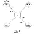
- the present invention relates to a system of matrix interconnected local area networks for the transmission of information between user terminals and equipment, e.g. databases, and access stations to other networks.
- a switching matrix provides a switched interface for linking together a number of local area networks, each network being provided with transmit and receive buses to which all its user terminals are connected, the buses further being connected to the switching matrix in a manner that enables the transmit and receive buses of different networks to be connected together in a particular sequence; each local area network is further provided with a master station for applying a unique call sign on its transmit bus to the switching matrix, and for monitoring its receive bus to detect the call sign of the local area network to which it is currently connected via the switching matrix, so that when a master station of a local area network detects a call sign of a different network it stops transmitting its call sign to allow the different network and the detecting network to communicate with each other.
- Each network is interconnected to a switching matrix SM by way of a transmit bus TBA and a receive bus RBA, for example.
- the buses may conveniently be optical fibre links or wires.
- Each local area network is provided with connections, such as C1-C3 for the connection of user terminals and other equipment to the system. All the user terminals are connected to the local area network by way of isolation circuits, to reduce the effect of faults on the system.
- the switching matrix SM takes the form of an optical matrix where optical fibre links are used for buses TB, RB, or the form of an electronic switching matrix where wires are used for the buses. With suitable conversion either switch type can be used with either transmission medium.
- the switching matrix comprises a number of switch cross-points but may be realised in any known configuration, e.g. a lattice arrangement as is currently used for optical switches.
- the switches are driven so as to connect each pair of transmit and receive buses TBA, RBA, for example, with another pair of buses, RBC, TBC for example.
- the switching matrix is shown in Figure 2, and in the present embodiment four pairs of buses are connected at a time, and the connection sequence is shown in Table 1. Therefore, there are four pairs of buses each carrying the local network bit rate.
- the timing of the sequence of Table 1 can be determined internally to the switching matrix SM by a pre-set sequential wave form generator driving the switches, and if required, the timing of the connection of four pairs can be made different to suit traffic predictions.
- the switching matrix can monitor the traffic flowing from each local area network and influence switching periods by the traffic pattern, within certain limits.
- each interconnection is made by metal oxide silicon (MOS) transistor having a controlling gate G, and connections D and S connected to respective local area network outputs and inputs.
- the control signals 1-4 are shown, and in Figure 3, the control signals 1 and 2 are presented to the controlling gates of the transistors to permit the output W of local area network LAN A to be switched to the input of local area network LAN B; and the output X of local area network LAN B to be switched to the input of local area network LAN A.
- MOS metal oxide silicon
- control signal 1 is at 0 volts, while control signal 2 is positive.
- the control signals may be free running or may be derived from the system and clocked if synchronism is required.
- Each local area network is provided with a master station which applies a unique call sign on its transmit bus traffic periods. All stations monitor their receive bus to detect the call sign of the local area network to which they are currently connected by way of the switching matrix.
- the transmit and receive signals for local area network LAN A are shown by way of an example.
- the local area network master station of LAN A detects call sign B, after a guard period it stops its call sign and allows the system to transmit traffic intended for local area network LAN B and vice versa.
- the master station for local area network LAN A starts to send its call sign again thus inhibiting further traffic, ready for switching to a different local area network, for example, LAN C.
- LAN C for example, LAN C.
- the local area networks can be of known types, suitably modified for this method of networking and can carry a mixture of voice, data and video.
- the working bit rates of local area networks are constantly being improved, and with four networks as described, a total traffic working bit rate approaching four times the rate of a single network can be achieved in a wide area network.
- the local area networks could take the form of a telecommunication exchange, such as a private automatic branch exchange PABX, suitably modified, where the PABX local highways are sequentially linked by way of the matrix switch.
- a telecommunication exchange such as a private automatic branch exchange PABX, suitably modified, where the PABX local highways are sequentially linked by way of the matrix switch.
Landscapes
- Engineering & Computer Science (AREA)
- Computer Networks & Wireless Communication (AREA)
- Signal Processing (AREA)
- Data Exchanges In Wide-Area Networks (AREA)
- Small-Scale Networks (AREA)
- Use Of Switch Circuits For Exchanges And Methods Of Control Of Multiplex Exchanges (AREA)
Applications Claiming Priority (2)
| Application Number | Priority Date | Filing Date | Title |
|---|---|---|---|
| GB8427748 | 1984-11-02 | ||
| GB848427748A GB8427748D0 (en) | 1984-11-02 | 1984-11-02 | Matrix interconnected local area networks |
Publications (1)
| Publication Number | Publication Date |
|---|---|
| EP0186941A1 true EP0186941A1 (fr) | 1986-07-09 |
Family
ID=10569149
Family Applications (1)
| Application Number | Title | Priority Date | Filing Date |
|---|---|---|---|
| EP85307278A Ceased EP0186941A1 (fr) | 1984-11-02 | 1985-10-11 | Réseaux locaux interconnectés de façon matricielle |
Country Status (4)
| Country | Link |
|---|---|
| EP (1) | EP0186941A1 (fr) |
| JP (1) | JPS61111039A (fr) |
| FI (1) | FI854265A7 (fr) |
| GB (2) | GB8427748D0 (fr) |
Families Citing this family (3)
| Publication number | Priority date | Publication date | Assignee | Title |
|---|---|---|---|---|
| GB2187367B (en) * | 1986-01-09 | 1990-03-28 | Ricoh Kk | Control system for local area network |
| US5043975A (en) * | 1989-06-29 | 1991-08-27 | Digital Equipment Corporation | High bandwidth network based on wavelength division multiplexing |
| JPH07158321A (ja) * | 1993-12-06 | 1995-06-20 | Kazuyuki Myoga | テント |
Citations (2)
| Publication number | Priority date | Publication date | Assignee | Title |
|---|---|---|---|---|
| WO1982003740A1 (fr) * | 1981-04-16 | 1982-10-28 | Ncr Co | Systeme de traitement de donnees utilisant une commutation par paquet de diffusion |
| EP0067431A2 (fr) * | 1981-06-12 | 1982-12-22 | Siemens Aktiengesellschaft | Réseau à plusieurs lignes de transmission de signaux optiques interconnectables par des mélangeurs optiques |
-
1984
- 1984-11-02 GB GB848427748A patent/GB8427748D0/en active Pending
-
1985
- 1985-08-01 GB GB08519371A patent/GB2166626B/en not_active Expired
- 1985-10-11 EP EP85307278A patent/EP0186941A1/fr not_active Ceased
- 1985-10-30 FI FI854265A patent/FI854265A7/fi not_active IP Right Cessation
- 1985-11-01 JP JP60244277A patent/JPS61111039A/ja active Granted
Patent Citations (2)
| Publication number | Priority date | Publication date | Assignee | Title |
|---|---|---|---|---|
| WO1982003740A1 (fr) * | 1981-04-16 | 1982-10-28 | Ncr Co | Systeme de traitement de donnees utilisant une commutation par paquet de diffusion |
| EP0067431A2 (fr) * | 1981-06-12 | 1982-12-22 | Siemens Aktiengesellschaft | Réseau à plusieurs lignes de transmission de signaux optiques interconnectables par des mélangeurs optiques |
Also Published As
| Publication number | Publication date |
|---|---|
| JPH0439251B2 (fr) | 1992-06-29 |
| GB2166626B (en) | 1988-08-03 |
| FI854265L (fi) | 1986-05-03 |
| JPS61111039A (ja) | 1986-05-29 |
| GB8519371D0 (en) | 1985-09-04 |
| GB8427748D0 (en) | 1984-12-12 |
| FI854265A7 (fi) | 1986-05-03 |
| GB2166626A (en) | 1986-05-08 |
| FI854265A0 (fi) | 1985-10-30 |
Similar Documents
| Publication | Publication Date | Title |
|---|---|---|
| US4723272A (en) | Telecommunication system, in particular telephone system | |
| US5341232A (en) | Star-shaped network for data communication between stations | |
| US4890279A (en) | Multiplexer and computer network using the same | |
| EP0561490B1 (fr) | Procédé pour établir des communications à large bande dans un système de commutation à division dans le temps | |
| EP0186941A1 (fr) | Réseaux locaux interconnectés de façon matricielle | |
| KR860009564A (ko) | 회로망 간 연결 시스템 | |
| JPS6054556A (ja) | 加入者接続デイジタル衛星局 | |
| EP0899914A4 (fr) | Dispositif et procede pour regulation de trafic en mode de transfert asynchrone (mta) | |
| JPH0813014B2 (ja) | モジュール式能動光ファイバカップラユニット及びそのシステム | |
| US3251945A (en) | Circuit arrangement constructed in the manner of a coupling multiple for the connection of time multiplex telephone systems | |
| CN85109293A (zh) | 在线路转接交换中提供数据服务的系统 | |
| KR920010221B1 (ko) | 선로 집중화 시스템 | |
| FI74860B (fi) | Kopplingsfaelt med foerbindelseomkastning, saerskilt foer telefoncentraler. | |
| JP2739070B2 (ja) | パケット交換システム | |
| JPS61164361A (ja) | 導通試験方式 | |
| RU2119263C1 (ru) | Цифровая коммутационная система | |
| SU964690A1 (ru) | Многоканальный матричный коммутатор | |
| FI863251A0 (fi) | Kopplingsanordning foer fjaerrkommunikationsfoermedlingsanlaeggningar, med kopplingsfaelt foer en- och flerkanalfoerbindelser. | |
| EP0243291A2 (fr) | Système de commutations simultanées de la parole et des données avec possibilités de connexion au réseau public ou privé | |
| JPS595796A (ja) | 遠隔局制御交換方式 | |
| JPS60247392A (ja) | 回線配分回路 | |
| JPS592475A (ja) | 呼種別呼損率制御方式 | |
| JPS63164734A (ja) | パケツト中継伝送装置 | |
| WO1988007295A1 (fr) | Reseau de communication | |
| JPS61192154A (ja) | 複合会議方式 |
Legal Events
| Date | Code | Title | Description |
|---|---|---|---|
| PUAI | Public reference made under article 153(3) epc to a published international application that has entered the european phase |
Free format text: ORIGINAL CODE: 0009012 |
|
| AK | Designated contracting states |
Kind code of ref document: A1 Designated state(s): AT BE CH DE FR IT LI LU NL SE |
|
| 17P | Request for examination filed |
Effective date: 19870124 |
|
| 17Q | First examination report despatched |
Effective date: 19881027 |
|
| STAA | Information on the status of an ep patent application or granted ep patent |
Free format text: STATUS: THE APPLICATION HAS BEEN REFUSED |
|
| 18R | Application refused |
Effective date: 19900210 |
|
| RIN1 | Information on inventor provided before grant (corrected) |
Inventor name: BEAUFOY, RAYMOND Inventor name: DELANEY, FRANK MICHAEL |