EP0186943B1 - Construction de la chambre de précombustion pour moteur à combustion interne - Google Patents
Construction de la chambre de précombustion pour moteur à combustion interne Download PDFInfo
- Publication number
- EP0186943B1 EP0186943B1 EP85307398A EP85307398A EP0186943B1 EP 0186943 B1 EP0186943 B1 EP 0186943B1 EP 85307398 A EP85307398 A EP 85307398A EP 85307398 A EP85307398 A EP 85307398A EP 0186943 B1 EP0186943 B1 EP 0186943B1
- Authority
- EP
- European Patent Office
- Prior art keywords
- cut
- precombustion chamber
- ring member
- ceramic body
- metal ring
- Prior art date
- Legal status (The legal status is an assumption and is not a legal conclusion. Google has not performed a legal analysis and makes no representation as to the accuracy of the status listed.)
- Expired
Links
- 238000010276 construction Methods 0.000 title claims description 24
- 238000002485 combustion reaction Methods 0.000 title claims description 10
- 239000000919 ceramic Substances 0.000 claims description 60
- 229910052751 metal Inorganic materials 0.000 claims description 32
- 239000002184 metal Substances 0.000 claims description 32
- 238000002347 injection Methods 0.000 claims description 4
- 239000007924 injection Substances 0.000 claims description 4
- 238000010438 heat treatment Methods 0.000 claims 1
- 239000007787 solid Substances 0.000 claims 1
- 229910010293 ceramic material Inorganic materials 0.000 description 11
- 239000000446 fuel Substances 0.000 description 5
- 241001272720 Medialuna californiensis Species 0.000 description 4
- 238000004880 explosion Methods 0.000 description 4
- 239000007789 gas Substances 0.000 description 2
- 239000000463 material Substances 0.000 description 2
- 150000002739 metals Chemical class 0.000 description 2
- 238000007789 sealing Methods 0.000 description 2
- 229910000838 Al alloy Inorganic materials 0.000 description 1
- 229910001018 Cast iron Inorganic materials 0.000 description 1
- 229910052581 Si3N4 Inorganic materials 0.000 description 1
- 239000000853 adhesive Substances 0.000 description 1
- 230000001070 adhesive effect Effects 0.000 description 1
- 230000006835 compression Effects 0.000 description 1
- 238000007906 compression Methods 0.000 description 1
- 230000008602 contraction Effects 0.000 description 1
- KZHJGOXRZJKJNY-UHFFFAOYSA-N dioxosilane;oxo(oxoalumanyloxy)alumane Chemical compound O=[Si]=O.O=[Si]=O.O=[Al]O[Al]=O.O=[Al]O[Al]=O.O=[Al]O[Al]=O KZHJGOXRZJKJNY-UHFFFAOYSA-N 0.000 description 1
- 239000002241 glass-ceramic Substances 0.000 description 1
- 229910052863 mullite Inorganic materials 0.000 description 1
Images


Classifications
-
- F—MECHANICAL ENGINEERING; LIGHTING; HEATING; WEAPONS; BLASTING
- F02—COMBUSTION ENGINES; HOT-GAS OR COMBUSTION-PRODUCT ENGINE PLANTS
- F02B—INTERNAL-COMBUSTION PISTON ENGINES; COMBUSTION ENGINES IN GENERAL
- F02B19/00—Engines characterised by precombustion chambers
- F02B19/16—Chamber shapes or constructions not specific to sub-groups F02B19/02 - F02B19/10
- F02B19/165—The shape or construction of the pre-combustion chambers is specially adapted to be formed, at least in part, of ceramic material
-
- F—MECHANICAL ENGINEERING; LIGHTING; HEATING; WEAPONS; BLASTING
- F02—COMBUSTION ENGINES; HOT-GAS OR COMBUSTION-PRODUCT ENGINE PLANTS
- F02B—INTERNAL-COMBUSTION PISTON ENGINES; COMBUSTION ENGINES IN GENERAL
- F02B19/00—Engines characterised by precombustion chambers
- F02B2019/006—Engines characterised by precombustion chambers with thermal insulation
-
- Y—GENERAL TAGGING OF NEW TECHNOLOGICAL DEVELOPMENTS; GENERAL TAGGING OF CROSS-SECTIONAL TECHNOLOGIES SPANNING OVER SEVERAL SECTIONS OF THE IPC; TECHNICAL SUBJECTS COVERED BY FORMER USPC CROSS-REFERENCE ART COLLECTIONS [XRACs] AND DIGESTS
- Y02—TECHNOLOGIES OR APPLICATIONS FOR MITIGATION OR ADAPTATION AGAINST CLIMATE CHANGE
- Y02T—CLIMATE CHANGE MITIGATION TECHNOLOGIES RELATED TO TRANSPORTATION
- Y02T10/00—Road transport of goods or passengers
- Y02T10/10—Internal combustion engine [ICE] based vehicles
- Y02T10/12—Improving ICE efficiencies
Definitions
- This invention relates to a precombustion chamber construction of an internal combustion engine and more particularly to a precombustion chamber made of a ceramic material to improve thermal efficiency of an engine and durability and heat-resistance of the precombustion chamber and having a metal ring fitted on ceramic members forming the precombustion chamber to facilitate handlign of the precombustion chamber.
- JP-A-58-162721 shows a precombustion chamber of this type.
- a precombustion chamber construction of an internal combustion engine consists of a lower chamber 3a and an upper chamber 3b made of a ceramic material and having pin receiving apertures 7 and 15 formed in the respective lower and upper chambers. Moreover, a cylinder head 1 is formed with a pin engaging recess 16 extending straight along an inner surface of a cavity of the cylinder head from its lower surface to the ceramic upper chamber 3b.
- the pins 9 are inserted in the pin receiving apertures 7 and 15, so that depression engaging portions 9b of the pins 9 engage within the pin engaging recess 16 so as to be press-fitted therein with interference, thereby fixing the ceramic chamber 3 to the metal cylinder head 1.
- the upper and lower chambers made of the ceramic material having the pins extending from the chambers, respectively, must be inserted separately into the precombustion receiving cavity formed in a lower side of the cylinder head. Accordingly, the assembling operation of the precombustion chamber construction is very troublesome because it is necessary to take care not to damage the ceramic members which are of high strength but brittle.
- the outer circumferences of the upper and lower ceramic bodies are cut-off segmentally, i.e. at a segment which is less than a semicircle and has a straight chord, to form the cut-away portions of the upper and lower ceramic bodies.
- the cut-away portions of the upper and lower ceramic bodies may alternatively be channel-shaped grooves.
- the precombustion chamber construction may further comprise a third key member receiver in cut-away portions formed in the upper and lower ceramic bodies at their abutting surfaces.
- the precombustion chamber construction 50 comprises an upper ceramic body 25, a lower ceramic body 26 abutting against it, a metal ring member 40 fitted on both the upper and lower ceramic bodies 25 and 26, a first key member 44 inserted in a key way consisting of a cut-away portion 45 formed in the upper ceramic body 25 and a groove 61 formed in the metal ring member 40, and a second key member 41 inserted in a key way consisting of a cut-away portion 46 formed in the lower ceramic body 26 and a groove 62 formed in the metal ring member 40.
- a reference numeral 47 denotes a thermal insulating air layer formed between the precombustion chamber construction receiving cavity 21 and the metal ring member 40.
- the thermal insluating air layer 47 is sealed by an upper end 48 and a lower end 49 of the metal ring member 40 by press-fitting the precombustion chamber construction 50 into the cylinder head 20.
- a knock ball 80 which is known per se may be interposed in a knock ball receiving recess 81 formed in the metal ring member 40 and a knock ball engaging recess 82 formed in the cylinder head 20 at its lower surface contacting the gasket 24 ( Figure 5).
- the cylinder head 20 is formed with a fuel injection nozzle receiving portion 31 and a glow-plug receiving portion 32, respectively, which communicate with a precombustion chamber 28 through apertures 33 and 34 formed in the upper ceramic body.
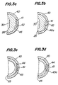
- a lower ceramic body 26 is formed in its outer periphery at a bottom with a segmental cut-away portion 46 for receiving part of a second key 41 in order to engage the ring member 40 with the lower ceramic body 26.
- the cut-away portion 46 is in the form of a half-moon which is less than a semicircle and has a straight chord.
- the cut-away portion 46 may be previously formed in the lower ceramic body 26 or may be formed after the ring member 40 is fitted thereon.
- the remaining portion of the second key member 41 is received in a channel-shaped groove 62 previously formed in the ring member 40.
- the dimension of the groove 62 is only required to meet the dimension of the second key member 41, particularly its width. Therefore, the operation of inserting the second key member 41 can be easly effected.
- a channel-shaped groove 46a similar to a groove 62 formed in a ring member 40 is formed in the outer periphery of a lower ceramic body 26 at its bottom.
- the channel shaped grooves 46a and 62 receive a second key member 41.
- an upper ceramic body 25 is formed with a segmental cut-away portion 45 in its outer periphery corresponding to an end face of a ring member for receiving part of a first key member in order to engage the ring member 40 with the upper ceramic body 25.
- the cut-away portion 45 is in the form of a half-moon which is less than a semicircle and has a straight chord.
- the cut-away portion 45 may be previously formed in the upper ceramic body 25 or may be formed often the ring member 40 is fitted thereon.
- the remaining portion of the first key member 44 is received in a groove 61 previously formed in the ring member 40.
- the dimension of the groove 61 is only required to meet the dimension of the first key member 44, particularly its width. Accordingly, the operation of inserting the first key member 44 can be easily effected.
- the first and second key members 44 and 41 may be fixed by press-fitting, thermal contraction or an adhesive. In this manner, the ring member 40 is integrally fixed to the upper ceramic body 25.
- a channel shaped grooves 45a similar to a groove 61 formed in a ring member 40.
- a key member 44 is received in the groove-shaped cut-away portion 45a and the groove 61.
- first and second key members 44 and 41 are arranged aligned with each other in Figure 2, the invention is not limited to such an alignment of the keys.
- first and second key members are shown to have square cross-sections, the invention is not limited to such figures.
- the key members may have a disc-like or elliptical cross-section.
- the cut-away portion in the ceramic body 25 or 26 in the form of the half-moon as shown at 45 or 46 in Figure 3a or 3c, because the working of the ceramic body is easy.
- the working of the ceramic body is more difficult than that of the half-moon cut-away portion, but it is more effective to prevent the relative rotative movement of the ceramic bodies.
- the ring member 40 can be integrally fixed to the lower ceramic body 26.
- varous kinds of metals can be used for the ring member 40, a heat-resistant metal is preferable in view of the condition of use.
- the ceramic bodies fixed to the ring membes by means of the key members have been explained, the ceramic bodies 25 and 26 may be prevented from rotating relative to each other by a third key member 27 received in cut-away portions formed in the upper and lower ceramic bodies 25 and 26 at their abutting surfaces 35 ( Figure 4).
- the upper and lower ceramic bodies are for example made of Si 3 N 4 , SiC, Zr0 2 , AI 2 0 3 , glass ceramics, mullite or the like.
- the key members are preferably made of one of these ceramic materials or a metal having a thermal expansion coefficient substantially equal to that of the ceramic material of the upper and lower ceramic bodies.
- the invention is not limited to such a material, and the key members may be made of a metal having a thermal expansion coefficient larger than that of the ceramic bodies, so long as the cut-away portions and grooves are made larger than the key members so as to prevent the upper and lower ceramic bodies from being cracked by the thermal expansion of the key members.
- the metal ring member is fitted on and keyed at its ends to the upper and lower ceramic bodies forming the precombustion chamber to form a unitary body, any relative rotative movement of the upper and lower ceramic bodies about their axes is prevented, even if they are subjected to rotating forces caused by explosions of a fuel and vibrations of an engine. Moreover, as the metal ring has the thermal expansion coefficient substantially equal to that of the cylinder head, holding force of the cylinder head for holding the precombustion chamber is not reduced during the operation of the engine.
- the metal ring member can be securely press-fitted in the cylinder head because the key members do not have parts extending from outer surfaces of the ring member which would otherwise obstruct the press-fitting of the ring member. Therefore, the precombustion chamber according to the invention can advantageously solve the problem of the relative rotative movement of the upper and lower ceramic bodies occurring when the holding force of the cylinder head for holding the precombustion chamber is reduced owing to the difference in thermal expansion coefficient between the ceramic material and the metal.
- the metal ring member integral with the ceramic bodies according to the invention can form easily in air layer superior in sealing between the metal ring member and the precombustion chamber construction receiving cavity of the cylinder head. Moreover, the integral construction of the metal ring member and the ceramic bodies can substantially completely avoid the damage of the ceramic bodies in assembling them in the cylinder head and in transferring them by collision with each other. As can be seen from the above description, the precombustion chamber of an internal combustion engine according to the invention has a number of advantages.
Landscapes
- Engineering & Computer Science (AREA)
- Chemical & Material Sciences (AREA)
- Ceramic Engineering (AREA)
- Combustion & Propulsion (AREA)
- Mechanical Engineering (AREA)
- General Engineering & Computer Science (AREA)
- Combustion Methods Of Internal-Combustion Engines (AREA)
Claims (5)
Applications Claiming Priority (4)
| Application Number | Priority Date | Filing Date | Title |
|---|---|---|---|
| JP155014/84 | 1984-10-16 | ||
| JP15501484U JPH03496Y2 (fr) | 1984-10-16 | 1984-10-16 | |
| JP12946685U JPH0240261Y2 (fr) | 1985-08-27 | 1985-08-27 | |
| JP129466/85 | 1985-08-27 |
Publications (2)
| Publication Number | Publication Date |
|---|---|
| EP0186943A1 EP0186943A1 (fr) | 1986-07-09 |
| EP0186943B1 true EP0186943B1 (fr) | 1989-05-17 |
Family
ID=26464839
Family Applications (1)
| Application Number | Title | Priority Date | Filing Date |
|---|---|---|---|
| EP85307398A Expired EP0186943B1 (fr) | 1984-10-16 | 1985-10-15 | Construction de la chambre de précombustion pour moteur à combustion interne |
Country Status (3)
| Country | Link |
|---|---|
| US (1) | US4616611A (fr) |
| EP (1) | EP0186943B1 (fr) |
| DE (1) | DE3570265D1 (fr) |
Families Citing this family (18)
| Publication number | Priority date | Publication date | Assignee | Title |
|---|---|---|---|---|
| JPH0212265Y2 (fr) * | 1985-06-24 | 1990-04-06 | ||
| JPH029067Y2 (fr) * | 1985-07-30 | 1990-03-06 | ||
| US4809654A (en) * | 1986-10-08 | 1989-03-07 | Ngk Insulators, Ltd. | Ceramic precombustion chamber construction of internal combustion engine |
| JPH0738656Y2 (ja) * | 1987-06-02 | 1995-09-06 | マツダ株式会社 | セラミック副室付シリンダ−ヘッド |
| JPS6444322U (fr) * | 1987-09-14 | 1989-03-16 | ||
| JP2718071B2 (ja) * | 1988-07-21 | 1998-02-25 | いすゞ自動車株式会社 | 副室式断熱エンジン |
| JPH0357818A (ja) * | 1989-07-27 | 1991-03-13 | Isuzu Motors Ltd | 副室の断熱構造 |
| JPH0357817A (ja) * | 1989-07-27 | 1991-03-13 | Isuzu Motors Ltd | 副室の断熱構造 |
| JPH0650054B2 (ja) * | 1989-08-10 | 1994-06-29 | いすゞ自動車株式会社 | 副室の断熱構造及びその製造法 |
| CN100410508C (zh) * | 2004-11-16 | 2008-08-13 | 天津大学 | 压缩点火气体燃料发动机燃烧系统及其复合供气方法 |
| KR100654705B1 (ko) | 2005-10-05 | 2006-12-06 | 최동수 | 도어 클로우저용 피스톤 |
| US10557407B2 (en) | 2011-07-28 | 2020-02-11 | Pratt & Whitney Canada Corp. | Rotary internal combustion engine with pilot subchamber |
| US10544732B2 (en) | 2011-07-28 | 2020-01-28 | Pratt & Whitney Canada Corp. | Rotary internal combustion engine with removable subchamber insert |
| US9038594B2 (en) | 2011-07-28 | 2015-05-26 | Pratt & Whitney Canada Corp. | Rotary internal combustion engine with pilot subchamber |
| US9528434B1 (en) | 2011-07-28 | 2016-12-27 | Pratt & Whitney Canada Corp. | Rotary internal combustion engine with pilot subchamber |
| US10041402B2 (en) | 2016-05-12 | 2018-08-07 | Pratt & Whitney Canada Corp. | Internal combustion engine with split pilot injection |
| US10145291B1 (en) | 2017-10-10 | 2018-12-04 | Pratt & Whitney Canada Corp. | Rotary engine and method of combusting fuel |
| US10801394B2 (en) | 2017-11-29 | 2020-10-13 | Pratt & Whitney Canada Corp. | Rotary engine with pilot subchambers |
Family Cites Families (8)
| Publication number | Priority date | Publication date | Assignee | Title |
|---|---|---|---|---|
| DE935468C (de) * | 1951-12-14 | 1955-11-17 | Plansee Metallwerk | Verfahren zur Herstellung einer festen Verbindung zwischen einem Koerper aus zaehem Werkstoff und einem diesen eng umschliessenden Koerper aus sproedem Werkstoff |
| DE1096845B (de) * | 1958-10-01 | 1961-01-12 | Wladimir Tiraspolsky | Vorrichtung zum Verkeilen von Schaufelraedern od. dgl. auf der Welle von Bohrturbinen, Axialpumpen od. dgl. |
| GB1534761A (en) * | 1977-01-07 | 1978-12-06 | Advanced Materials Eng | Indirect injection diesel engines |
| JPS5922044B2 (ja) * | 1978-11-06 | 1984-05-24 | トヨタ自動車株式会社 | 内燃機関の渦流室の構造 |
| JPS5623517A (en) * | 1979-08-02 | 1981-03-05 | Toshiba Corp | Sub-combustion chamber in internal combustion engine |
| DE3133209C2 (de) * | 1981-08-21 | 1985-04-25 | MTU Motoren- und Turbinen-Union München GmbH, 8000 München | Hohler Verbundkörper, insbesondere Umdrehungskörper und Verfahren zu seiner Herstellung |
| JPS5946317A (ja) * | 1982-09-07 | 1984-03-15 | Toyota Motor Corp | 内燃機関の燃焼室部品 |
| JPS5958119A (ja) * | 1982-09-28 | 1984-04-03 | Mitsubishi Heavy Ind Ltd | 副室式デイ−ゼル機関の燃焼室 |
-
1985
- 1985-10-11 US US06/786,487 patent/US4616611A/en not_active Expired - Fee Related
- 1985-10-15 EP EP85307398A patent/EP0186943B1/fr not_active Expired
- 1985-10-15 DE DE8585307398T patent/DE3570265D1/de not_active Expired
Also Published As
| Publication number | Publication date |
|---|---|
| EP0186943A1 (fr) | 1986-07-09 |
| DE3570265D1 (en) | 1989-06-22 |
| US4616611A (en) | 1986-10-14 |
Similar Documents
| Publication | Publication Date | Title |
|---|---|---|
| US4616611A (en) | Precombustion chamber construction of internal combustion engine | |
| US4662331A (en) | Precombustion chamber construction of internal combustion engine | |
| JPH0212265Y2 (fr) | ||
| US4699102A (en) | Structure for mounting sub-combustion chamber in an internal combustion engine | |
| US4513703A (en) | Reciprocating piston internal combustion engine | |
| US4089306A (en) | Port insulation for internal combustion engines | |
| US4875939A (en) | Precombustion chamber construction for an internal combustion engine | |
| JPS608449A (ja) | エンジンの耐熱応力構造 | |
| JPS61123714A (ja) | 内燃機関の副室構造 | |
| JPS5941007B2 (ja) | 機関燃焼室の構造 | |
| JPH0240261Y2 (fr) | ||
| US4691673A (en) | Ceramic auxiliary combustion chamber | |
| EP0019972B1 (fr) | Piston pour moteurs à combustion interne comprenant un segment pare-flammes flottant | |
| JPH029068Y2 (fr) | ||
| EP0167528B1 (fr) | Culasse en ceramique pour moteur a combustion interne | |
| EP0780554B1 (fr) | Construction de piston avec chambre de combustion calorifugée | |
| US4614172A (en) | Cylinder head for internal combustion engine | |
| JPH03496Y2 (fr) | ||
| JPS59188025A (ja) | デイ−ゼルエンジンの副燃焼室組立方法 | |
| JPS63235648A (ja) | エンジンの断熱ピストン構造 | |
| JPH0422035Y2 (fr) | ||
| JPH029066Y2 (fr) | ||
| JPS61294119A (ja) | 内燃機関のセラミツクス製副室 | |
| JPS6226319A (ja) | 内燃機関のセラミツクス製副室 | |
| JPH0319902B2 (fr) |
Legal Events
| Date | Code | Title | Description |
|---|---|---|---|
| PUAI | Public reference made under article 153(3) epc to a published international application that has entered the european phase |
Free format text: ORIGINAL CODE: 0009012 |
|
| 17P | Request for examination filed |
Effective date: 19851129 |
|
| AK | Designated contracting states |
Kind code of ref document: A1 Designated state(s): DE FR GB |
|
| 17Q | First examination report despatched |
Effective date: 19870211 |
|
| GRAA | (expected) grant |
Free format text: ORIGINAL CODE: 0009210 |
|
| AK | Designated contracting states |
Kind code of ref document: B1 Designated state(s): DE FR GB |
|
| REF | Corresponds to: |
Ref document number: 3570265 Country of ref document: DE Date of ref document: 19890622 |
|
| ET | Fr: translation filed | ||
| PLBE | No opposition filed within time limit |
Free format text: ORIGINAL CODE: 0009261 |
|
| STAA | Information on the status of an ep patent application or granted ep patent |
Free format text: STATUS: NO OPPOSITION FILED WITHIN TIME LIMIT |
|
| 26N | No opposition filed | ||
| PGFP | Annual fee paid to national office [announced via postgrant information from national office to epo] |
Ref country code: GB Payment date: 19941006 Year of fee payment: 10 |
|
| PGFP | Annual fee paid to national office [announced via postgrant information from national office to epo] |
Ref country code: FR Payment date: 19941014 Year of fee payment: 10 |
|
| PGFP | Annual fee paid to national office [announced via postgrant information from national office to epo] |
Ref country code: DE Payment date: 19941017 Year of fee payment: 10 |
|
| PG25 | Lapsed in a contracting state [announced via postgrant information from national office to epo] |
Ref country code: GB Effective date: 19951015 |
|
| GBPC | Gb: european patent ceased through non-payment of renewal fee |
Effective date: 19951015 |
|
| PG25 | Lapsed in a contracting state [announced via postgrant information from national office to epo] |
Ref country code: FR Effective date: 19960628 |
|
| PG25 | Lapsed in a contracting state [announced via postgrant information from national office to epo] |
Ref country code: DE Effective date: 19960702 |
|
| REG | Reference to a national code |
Ref country code: FR Ref legal event code: ST |