EP0187038A2 - Drehmoment mit hohem Drehmomentpolen und magnetischer Zentrierung durch Federeinstellung - Google Patents
Drehmoment mit hohem Drehmomentpolen und magnetischer Zentrierung durch Federeinstellung Download PDFInfo
- Publication number
- EP0187038A2 EP0187038A2 EP85309435A EP85309435A EP0187038A2 EP 0187038 A2 EP0187038 A2 EP 0187038A2 EP 85309435 A EP85309435 A EP 85309435A EP 85309435 A EP85309435 A EP 85309435A EP 0187038 A2 EP0187038 A2 EP 0187038A2
- Authority
- EP
- European Patent Office
- Prior art keywords
- stator
- motor
- rotor
- flanges
- stator pole
- Prior art date
- Legal status (The legal status is an assumption and is not a legal conclusion. Google has not performed a legal analysis and makes no representation as to the accuracy of the status listed.)
- Withdrawn
Links
- 230000003993 interaction Effects 0.000 claims abstract description 12
- 230000004907 flux Effects 0.000 claims abstract description 9
- 239000000696 magnetic material Substances 0.000 claims description 7
- 230000008859 change Effects 0.000 abstract description 3
- BGPVFRJUHWVFKM-UHFFFAOYSA-N N1=C2C=CC=CC2=[N+]([O-])C1(CC1)CCC21N=C1C=CC=CC1=[N+]2[O-] Chemical compound N1=C2C=CC=CC2=[N+]([O-])C1(CC1)CCC21N=C1C=CC=CC1=[N+]2[O-] BGPVFRJUHWVFKM-UHFFFAOYSA-N 0.000 description 5
- XEEYBQQBJWHFJM-UHFFFAOYSA-N Iron Chemical compound [Fe] XEEYBQQBJWHFJM-UHFFFAOYSA-N 0.000 description 4
- 239000012530 fluid Substances 0.000 description 4
- 238000004804 winding Methods 0.000 description 4
- 238000006073 displacement reaction Methods 0.000 description 3
- 230000000712 assembly Effects 0.000 description 2
- 238000000429 assembly Methods 0.000 description 2
- 230000003247 decreasing effect Effects 0.000 description 2
- 229910052742 iron Inorganic materials 0.000 description 2
- 230000009467 reduction Effects 0.000 description 2
- 230000004323 axial length Effects 0.000 description 1
- DMFGNRRURHSENX-UHFFFAOYSA-N beryllium copper Chemical compound [Be].[Cu] DMFGNRRURHSENX-UHFFFAOYSA-N 0.000 description 1
- 238000010276 construction Methods 0.000 description 1
- 238000013016 damping Methods 0.000 description 1
- 210000003127 knee Anatomy 0.000 description 1
- 239000000463 material Substances 0.000 description 1
- 239000007787 solid Substances 0.000 description 1
Images


Classifications
-
- H—ELECTRICITY
- H01—ELECTRIC ELEMENTS
- H01F—MAGNETS; INDUCTANCES; TRANSFORMERS; SELECTION OF MATERIALS FOR THEIR MAGNETIC PROPERTIES
- H01F7/00—Magnets
- H01F7/06—Electromagnets; Actuators including electromagnets
- H01F7/08—Electromagnets; Actuators including electromagnets with armatures
- H01F7/14—Pivoting armatures
- H01F7/145—Rotary electromagnets with variable gap
-
- H—ELECTRICITY
- H02—GENERATION; CONVERSION OR DISTRIBUTION OF ELECTRIC POWER
- H02K—DYNAMO-ELECTRIC MACHINES
- H02K26/00—Machines adapted to function as torque motors, i.e. to exert a torque when stalled
Definitions
- This invention relates generally as indicated to a torque motor with high torque poles and magnetic centering spring adjustment.
- the motor of the present invention relates to certain improvements in a limited angle torque motor generally of a type which is particularly suited for use in certain types of high pressure fluid proportional servo control systems including, but not limited to, aircraft controls to drive a proportional control valve of relatively short stroke.
- the fluid pressure is normally on the order of 1,000 psi or more.
- the motor includes a rotor assembly having one or more permanent magnets and a stator assembly including a stator coil and a pair of circumferentially spaced stator pole structures.
- Each stator pole structure includes a generally axially extending stator pole blade about which the stator coil circumferentially extends, and a radially outwardly extending flange at one end of one of the stator pole structures and at the opposite end of the other stator pole structure.
- the stator pole blades have a greater radial thickness adjacent the flanges thereof than at the opposite ends of the blades to reduce the magnetic flux density of the stator pole structures in the region of the blades adjacent the flanges thereof.
- the axial outer end faces of the stator pole flanges desirably protrude axially outwardly adjacent the radial inner ends thereof to make use of the fringing fields of the rotor magnet at the ends of the rotor assembly to increase the reluctance torque of the motor.
- additional stator pole pieces are provided at the ends of the stator assembly opposite the stator pole flanges on opposite sides of the rotor assembly.
- the blades of the stator pole structures terminate short of the other ends of the rotor magnet to provide room for the additional pole pieces at such other ends for a given rotor length thereby providing the motor with a substantially higher reluctance torque without significantly reducing the torque due to interaction of magnetic fields.
- an outer magnetic housing comprising two semi-cylindrical parts with air gaps between opposite sides thereof surrounds the stator assembly, said housing parts being rotatable relative to each other to change the size of one gap relative to the other for adjusting the reluctance torque of the motor.
- a preferred form of limited angle torque motor in accordance with this invention is generally indicated by the reference numeral 1.
- Such motor is primarily intended for use in high pressure fluid systems for directly driving a valve in proportional servo control systems including, but not limited to, aircraft controls. However, it should be understood that such motor could also be used for driving secondary valves as well as other mechanical devices.
- the motor is a non-commutated two-pole stationary coil rotary magnetic motor consisting of a rotor assembly 2 including a rotor shaft 3 having one or more permanent magnets 5 intermediate the ends thereof, and a stator assembly 6 surrounding the rotor assembly.
- the rotor magnet 5 is magnetized in the diametrical direction so that the North and South poles N and S are diametrically oriented as illustrated in Figure 2.
- the rotor shaft may be suitably journaled within a rotor housing 7 for rotation of the rotor assembly 2 relative to the stator assembly 6.
- a relatively small flux path clearance 8 separates the rotor and stator assemblies, thereby permitting rotation of the rotor assembly relative to the stator assembly through its rotational angle range.
- the stator assembly includes one or more high density layer wound stator coils 9 circumferentially extending around a pair of magnetic stator pole structures 10, 11 with the axis of the stator windings being generally parallel to the rotor axis.
- stator pole structures 10, 11 are circumferentially spaced from each other, and each includes an axially extending pole blade 14 and a flange 15 extending radially outwardly from one end only of each pole structure, such flanges being at opposite ends of the respective pole structures.
- the stator pole flanges 15 are integral with the stator pole blades 14 and desirably extend radially outwardly into contact with the overlapping inner surface of an outer magnetic housing 16 surrounding the stator assembly.
- the magnetic housing is made of a suitable magnetic material such as soft iron, and provides a magnetic return path for the magnetic field when the stator coil is excited. Such magnetic return path may be partially interrupted by providing one or more air gaps 17, 18 in the outer magnetic housing as shown in Figure 2.
- stator pole structures 10, 11 may be centrally supported by a suitable stator support sleeve 19 which is desirably made from a material having high electrical conductivity such as beryllium copper that produces significant eddy current damping for system dynamic requirements and is also sufficiently strong to withstand any internal fluid pressures that the stator assembly may be subjected to.
- a suitable stator support sleeve 19 which is desirably made from a material having high electrical conductivity such as beryllium copper that produces significant eddy current damping for system dynamic requirements and is also sufficiently strong to withstand any internal fluid pressures that the stator assembly may be subjected to.
- FIG. 4 graphically illustrates the general torque versus angular shaft position profile of a representative motor constructed in accordance with this invention when a current of ⁇ I is applied to the stator coil.
- a negative current (-I) when a negative current (-I) is applied, a negative torque tending to rotate the rotor shaft in a counterclockwise direction is produced over the same excursion of the rotor shaft.
- stator pole structures 10, 11 are made as thin as practical to maximize the number of coil windings (i.e. ampere turns) for a given space within the stator assembly.
- stator pole structures are made too thin, as the rotor displacement is increased from the null or centered position shown in Figure 2, the magnetic material in the regions A ( Figure 1) at the ends of the stator pole blades 14 from which the stator pole flanges 15 extend will saturate too quickly, thereby reducing the component of the magnetic field due to the coil ampere turns. This in turn reduces the interaction of magnetic fields torque that can be produced by the motor.
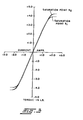
- Figure 3 shows the interaction of magnetic fields torque for different levels of applied current for a representative motor constructed in accordance with this invention.
- the saturation point S l (which occurs in the region A of the stator pole structures) is a rather sharply defined knee, which may be used as a magnetic stop to establish the maximum rotational stroke of the motor shaft for a given stator design.
- the torque versus current characteristic of the motor can be increased by increasing the magnetic cross-sectional area of the stator pole blade 14 of each stator pole structure 10, 11 in the region A immediately adjacent the axial inner face of the radial flange 15 thereof. This reduces the magnetic flux density in such region and thereby increases the maximum output torque of the rotor shaft for a given stator design at which the saturation point S 2 is reached as further graphically illustrated in Figure 3.
- each stator pole blade 14 is preferably made radially thicker by providing an enlarged step 20 for a portion of the length thereof commencing at the radial flange.
- the stator pole blade may be provided with a thickness of approximately one and one-half times the thickness of the remaining blade portion over a length of approximately one-fourth to one-third the free length of the stator pole blade commencing at such stator pole flange.
- Such increased radial thickness for a portion of the length of the stator pole blade will provide the desired reduction in the magnetic flux density without significantly reducing the coil window area between the stator pole structures and magnetic housing for the coil windings so as to minimize the reduction in the number of coil windings in the motor itself.
- a magnetic reluctance torque is developed by the magnetic flux produced by the permanent rotor magnet 5 that tends to keep the rotor assembly at the midpoint of its rotational angle range shown in Figure 2.
- the magnetic reluctance torque develops a restoring torque which varies in magnitude with rotation and acts in opposition to the applied external force tending to return the rotor North and South poles to the original centered position as also graphically illustrated in Figure 4.
- the reluctance torque of the motor can be increased by providing additional magnetic material in the regions B on the axial outer end faces of the stator pole flanges to make use of the fringing fields of the permanent magnet 5 at the ends of the rotor assembly 2.
- a shoulder portion 21 is provided on the axial outer face of each stator pole flange 15 which extends from the radial inner edge thereof approximately one and one-half times the thickened portions of the stator pole blades or approximately equal to the thickness of the enlarged step 20 of the blades.
- shoulder portions 21 desirably have an axial thickness of approximately one and one-quarter to one and one-half times the axial thickness of the radial outer end of the radial flanges.
- an additional centering reluctance torque can be produced by providing in place of the usual nonmagnetic end plates at the ends of the stator assembly opposite the stator pole flanges, one-half of a solid magnetic pole piece 24 at such ends on opposite sides of the rotor assembly.
- each such pole piece 24 consists of a half outer ring 25 structure of highly permeable soft magnetic iron having radially inwardly extending pole extensions 26 at opposite ends of the half ring which terminate in closely spaced relation to the rotor magnet 5.
- the additional reluctance torque produced by such additional pole pieces 24 is proportional to the axial length of such additional pole pieces. Accordingly, such reluctance torque can be further increased by decreasing somewhat the length of the stator pole blades 14 and eliminating a portion of the coil radially outwardly of the removed stator pole blade end portions to accommodate longer pole pieces 24 for a given rotor length.
- the removal of a small portion of the length of the stator pole blades, for example one-sixth to one-fifth the length thereof, and the surrounding coil portion does not significantly reduce the torque due to interaction of magnetic fields, but does provide a substantially higher reluctance torque.
- the rotor shaft has a maximum travel of approximately ⁇ 20° when a current ⁇ I is applied to the stator coil.
- Point 1 represents a typical operating condition in which a positive or opening torque +T ⁇ 1 is available at a positive displacement 9 1 and positive current +I.
- Point 2 illustrates the large negative or closing torque -T ⁇ 1 that is available if the current is reversed with the rotor at the same position (0 1 ). This large torque is due to the space-phase relationships between the reluctance and interaction of magnetic fields torque components illustrated in Figure 4.
- the reluctance torque versus displacement characteristic of the motor can also be adjusted by changing the size of the gaps 17, 18 in the outer magnetic housing 16 to vary the reluctance of the magnetic circuit.
- This may readily be accomplished in accordance with the present invention by forming the outer magnetic housing 16 in two semi-cylindrical parts 30, 31 with the gaps 17, 18 between each part on opposite sides of the housing. Accordingly, if the two outer housing parts 30, 31 are rotated relative to each other, the size of one gap will be changed with respect to the other gap. Whenever the size of either gap is reduced from the average, the reluctance torque is decreased and the interaction of magnetic fields torque is increased.
Landscapes
- Physics & Mathematics (AREA)
- Electromagnetism (AREA)
- Engineering & Computer Science (AREA)
- Power Engineering (AREA)
- Synchronous Machinery (AREA)
- Reciprocating, Oscillating Or Vibrating Motors (AREA)
- Permanent Field Magnets Of Synchronous Machinery (AREA)
Applications Claiming Priority (2)
| Application Number | Priority Date | Filing Date | Title |
|---|---|---|---|
| US06/685,036 US4612526A (en) | 1984-12-21 | 1984-12-21 | Torque motor with high torque poles and magnetic centering spring adjustment |
| US685036 | 1984-12-21 |
Publications (2)
| Publication Number | Publication Date |
|---|---|
| EP0187038A2 true EP0187038A2 (de) | 1986-07-09 |
| EP0187038A3 EP0187038A3 (de) | 1987-01-14 |
Family
ID=24750533
Family Applications (1)
| Application Number | Title | Priority Date | Filing Date |
|---|---|---|---|
| EP85309435A Withdrawn EP0187038A3 (de) | 1984-12-21 | 1985-12-23 | Drehmoment mit hohem Drehmomentpolen und magnetischer Zentrierung durch Federeinstellung |
Country Status (3)
| Country | Link |
|---|---|
| US (1) | US4612526A (de) |
| EP (1) | EP0187038A3 (de) |
| JP (1) | JPS61180562A (de) |
Cited By (2)
| Publication number | Priority date | Publication date | Assignee | Title |
|---|---|---|---|---|
| GB2199450A (en) * | 1986-11-25 | 1988-07-06 | Messerschmitt Boelkow Blohm | Electromagnetic adjustment assembly |
| RU2378755C1 (ru) * | 2008-12-01 | 2010-01-10 | Государственное образовательное учреждение высшего профессионального образования Томский политехнический университет | Моментный двигатель |
Families Citing this family (11)
| Publication number | Priority date | Publication date | Assignee | Title |
|---|---|---|---|---|
| US5038064A (en) * | 1990-08-31 | 1991-08-06 | Briggs & Stratton Corporation | Limited angle rotary actuator |
| US5287835A (en) * | 1992-07-10 | 1994-02-22 | Briggs & Stratton Corporation | Electronic governor with fast response time |
| US5337030A (en) * | 1992-10-08 | 1994-08-09 | Lucas Industries, Inc. | Permanent magnet brushless torque actuator |
| US5327032A (en) * | 1993-02-18 | 1994-07-05 | Carter Automotive Company, Inc. | Dual flux ring multiple position rotary actuator |
| US5677580A (en) * | 1993-11-08 | 1997-10-14 | Sl Montevideo Technology, Inc. | Transversal-flux permanent magnet motor |
| US5990584A (en) * | 1998-08-25 | 1999-11-23 | Eaton Corporation | Direct current torque motor with extended stator poles |
| US6269838B1 (en) | 1998-12-22 | 2001-08-07 | Raymond Dexter Woodworth | Rotary servovalve and control system |
| US6424070B1 (en) * | 2000-08-14 | 2002-07-23 | Moog Inc. | Magnetically centering torque motor |
| US6750748B2 (en) | 2001-08-09 | 2004-06-15 | Delphi Technologies, Inc. | Limited angle unidirectional torque motor |
| EP2262084A1 (de) | 2009-06-12 | 2010-12-15 | Braun GmbH | Elektromotor für ein elektrisches Kleingerät |
| CN110778772B (zh) * | 2018-07-31 | 2021-11-02 | 浙江三花智能控制股份有限公司 | 电磁驱动装置及具有该电磁驱动装置的燃气比例阀 |
Family Cites Families (10)
| Publication number | Priority date | Publication date | Assignee | Title |
|---|---|---|---|---|
| US2767357A (en) * | 1952-09-10 | 1956-10-16 | Molyneux & Aspinwall Inc | Electromagnetic actuator |
| US3157803A (en) * | 1961-06-28 | 1964-11-17 | Jr Sterling Graydon | Split-armature rotary solenoid |
| US3144593A (en) * | 1961-12-11 | 1964-08-11 | Raymond J Ganowsky | Rotary solenoid |
| US3234436A (en) * | 1962-09-12 | 1966-02-08 | Daco Instr Company Inc | Rotary electromagnetic actuator |
| US3201661A (en) * | 1963-01-11 | 1965-08-17 | Clary Corp | Rotary solenoid having a rectangular stator member |
| US3694782A (en) * | 1970-11-20 | 1972-09-26 | Ralph D Ray | Rotary actuator |
| GB1509907A (en) * | 1974-08-14 | 1978-05-04 | Lucas Industries Ltd | Electro-magnetic actuating devices |
| US4135138A (en) * | 1977-01-12 | 1979-01-16 | Mcclintock Manufacturing Corporation | Rotary solenoid |
| JPS5434014A (en) * | 1977-08-20 | 1979-03-13 | Shinano Tokki Kk | Electromagnetic rotating apparatus |
| US4510403A (en) * | 1984-02-13 | 1985-04-09 | Pneumo Corporation | Limited angle torque motor with magnetic centering and stops |
-
1984
- 1984-12-21 US US06/685,036 patent/US4612526A/en not_active Expired - Fee Related
-
1985
- 1985-12-20 JP JP60285846A patent/JPS61180562A/ja active Pending
- 1985-12-23 EP EP85309435A patent/EP0187038A3/de not_active Withdrawn
Cited By (3)
| Publication number | Priority date | Publication date | Assignee | Title |
|---|---|---|---|---|
| GB2199450A (en) * | 1986-11-25 | 1988-07-06 | Messerschmitt Boelkow Blohm | Electromagnetic adjustment assembly |
| GB2199450B (en) * | 1986-11-25 | 1991-01-02 | Messerschmitt Boelkow Blohm | Electromagnetic adjustment assembly |
| RU2378755C1 (ru) * | 2008-12-01 | 2010-01-10 | Государственное образовательное учреждение высшего профессионального образования Томский политехнический университет | Моментный двигатель |
Also Published As
| Publication number | Publication date |
|---|---|
| JPS61180562A (ja) | 1986-08-13 |
| EP0187038A3 (de) | 1987-01-14 |
| US4612526A (en) | 1986-09-16 |
Similar Documents
| Publication | Publication Date | Title |
|---|---|---|
| US4510403A (en) | Limited angle torque motor with magnetic centering and stops | |
| US4612526A (en) | Torque motor with high torque poles and magnetic centering spring adjustment | |
| US4719378A (en) | Brushless motor having permanent magnet rotor and salient pole stator | |
| US8198774B2 (en) | Permanent magnet motor | |
| US4029977A (en) | Rotary stepper motor and method of operation | |
| US4816707A (en) | Limited angle torque motor with wide rotation poles | |
| US5038064A (en) | Limited angle rotary actuator | |
| JP3470689B2 (ja) | リニアアクチュエータ | |
| EP0186501B1 (de) | Winkelbegrenzter Drehmomentmotor grosser Starrheit und Eigenfrequenz | |
| KR100582804B1 (ko) | 토오크 모터 및 그 제조 방법 | |
| US4600910A (en) | Limited angle torque motor with high torque output multiple coils and increased magnetic centering torque | |
| US20050116800A1 (en) | Rotary actuator | |
| JPH07106051B2 (ja) | アクチュエータ | |
| US5703555A (en) | Rotary actuator | |
| US7135947B2 (en) | Hybrid microwave T-switch actuator | |
| KR19990006818A (ko) | 움직일 수 있는 영구 자석을 갖춘 전자기 구동 장치 | |
| GB1461397A (en) | Electromagnetic rotary actuators | |
| US4908592A (en) | Electromagnetic actuating device | |
| US5004940A (en) | Direct drive valve force motor with gain shaping provision | |
| US6750748B2 (en) | Limited angle unidirectional torque motor | |
| EP1117175A2 (de) | Klauenpoldrehmomentmotor und diesen benutzendes Drosselventil | |
| US5682129A (en) | Electrical actuator | |
| JPH043585Y2 (de) | ||
| US6075774A (en) | Method and device for generating a frame check sequence | |
| KR930005344B1 (ko) | 액튜에이터 |
Legal Events
| Date | Code | Title | Description |
|---|---|---|---|
| PUAI | Public reference made under article 153(3) epc to a published international application that has entered the european phase |
Free format text: ORIGINAL CODE: 0009012 |
|
| AK | Designated contracting states |
Kind code of ref document: A2 Designated state(s): DE GB |
|
| PUAL | Search report despatched |
Free format text: ORIGINAL CODE: 0009013 |
|
| AK | Designated contracting states |
Kind code of ref document: A3 Designated state(s): DE GB |
|
| RAP1 | Party data changed (applicant data changed or rights of an application transferred) |
Owner name: PNEUMO ABEX CORPORATION |
|
| 17P | Request for examination filed |
Effective date: 19870702 |
|
| STAA | Information on the status of an ep patent application or granted ep patent |
Free format text: STATUS: THE APPLICATION HAS BEEN WITHDRAWN |
|
| 18W | Application withdrawn |
Withdrawal date: 19890521 |
|
| R18W | Application withdrawn (corrected) |
Effective date: 19890521 |
|
| RIN1 | Information on inventor provided before grant (corrected) |
Inventor name: VANDERLAAN, ROBERT D. Inventor name: EISZNER, WILLIAM H., JR. |