EP0186501B1 - Winkelbegrenzter Drehmomentmotor grosser Starrheit und Eigenfrequenz - Google Patents
Winkelbegrenzter Drehmomentmotor grosser Starrheit und Eigenfrequenz Download PDFInfo
- Publication number
- EP0186501B1 EP0186501B1 EP85309436A EP85309436A EP0186501B1 EP 0186501 B1 EP0186501 B1 EP 0186501B1 EP 85309436 A EP85309436 A EP 85309436A EP 85309436 A EP85309436 A EP 85309436A EP 0186501 B1 EP0186501 B1 EP 0186501B1
- Authority
- EP
- European Patent Office
- Prior art keywords
- motor
- magnetic
- centering spring
- rotor
- permanent magnets
- Prior art date
- Legal status (The legal status is an assumption and is not a legal conclusion. Google has not performed a legal analysis and makes no representation as to the accuracy of the status listed.)
- Expired
Links
Images


Classifications
-
- H—ELECTRICITY
- H01—ELECTRIC ELEMENTS
- H01F—MAGNETS; INDUCTANCES; TRANSFORMERS; SELECTION OF MATERIALS FOR THEIR MAGNETIC PROPERTIES
- H01F7/00—Magnets
- H01F7/06—Electromagnets; Actuators including electromagnets
- H01F7/08—Electromagnets; Actuators including electromagnets with armatures
- H01F7/14—Pivoting armatures
- H01F7/145—Rotary electromagnets with variable gap
-
- H—ELECTRICITY
- H02—GENERATION; CONVERSION OR DISTRIBUTION OF ELECTRIC POWER
- H02K—DYNAMO-ELECTRIC MACHINES
- H02K26/00—Machines adapted to function as torque motors, i.e. to exert a torque when stalled
Definitions
- This invention relates generally as indicated to a limited angle torque motor with high stiffness and natural frequency.
- the motor of the present invention is particularly suited for use in certain types of high pressure fluid proportional servo control systems including, but not limited to, aircraft controls to drive a proportional control valve of relatively short stroke.
- the fluid pressure is normally on the order of 1,000 psi or more.
- the magnetic reluctance torque of the motor can be controlled within certain limits to obtain a particular desired inherent magnetic centering spring rate at a particular torque or power level.
- a motor has a somewhat limited magnetic spring capability inherent in the design, and there are some applications in which it is desirable for the motor to have a higher centering spring gradient to increase the dynamic stiffness of a servo system, e.g. where the motor is being used to drive a load having substantial and varying force levels.
- Such a motor also has a torsional undamped natural frequency which is generally related to the magnetic spring rate through the center position and rotational inertia of the rotor.
- Typical such natural frequencies have been limited to about 60 Hertz (Hz) for motors of practical design.
- Hz Hertz
- a limited angle torque motor comprising a motor power section including a rotor assembly having a permanent rotor magnet magnetized in the diametrical direction and a stator assembly surrounding said rotor assembly, characterized by a separate magnetic centering spring section axially adjacent said motor power section, said centering spring section comprising an outer magnetic ring at one end of said stator assembly, said rotor assembly including said rotor magnet extending coaxially into said outer ring, and additional permanent magnets carried by said outer ring on diametrically opposite sides of the extended portion of said rotor assembly, the polarities of said additional permanent magnets being aligned with respect to said rotor magnet.
- a limited angle torque motor with a relatively high spring gradient to increase the undamped natural frequency of the motor and/or provide high system stiffness when coupled to a servo system having significant and varying load forces.
- the magnetic flux in the motor power section produces an inherent centering spring rate tending to keep the rotor assembly at the midpoint of its rotational angle range.
- a direct or pulse width modulated current is applied to the stator windings, a cross flux is produced through the stator and rotor assemblies of the motor power section which produces the desired limited rotational angle range for the rotor assembly.
- the magnetic centering spring section which is separate from the motor power section, provides another centering spring function in addition to the basic centering spring function inherent in the motor power section.
- Figure 1 is a fragmentary longitudinal section through one form of limited angle torque motor in accordance with the present invention
- Figure 2 is a fragmentary transverse section through the motor power section of the motor of Figure 1 taken substantially along the plane of the line 2-2 thereof
- Figure 3 is a transverse section through the magnetic centering spring section of the motor of Figure 1 taken substantially along the plane of the line 3-3 thereof
- Figure 4 is a schematic diagram showing the rotor magnetic pull both of the magnetic centering spring section by itself and when combined with the inherent magnetic spring capability of the motor power section to increase the net centering gradient of the motor rotor
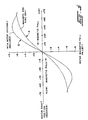
- Figure 5 is a graphic illustration showing the motor shaft position for different levels of applied direct or pulse width modulated current for a representative motor constructed in accordance with this invention
- Figures 6 and 7 are transverse sections similar to Figure 3 but showing alternate forms of magnetic centering spring sections for use in place of the centering spring section of Figure 1.
- the motor is a non-commutated two-pole stationary coil rotary magnet motor having a motor power section 2 including a rotor assembly 3 having a rotor shaft 4 with one or more permanent magnets 5 supported for rotation therewith.
- the rotor magnet or magnets 5 are rare earth magnets made, for example, of samarium cobalt, and are magnetized in the diametrical direction, that is, the North and South poles N and S of the rotor magnets are diametrically oriented as shown in Figure 2.
- the rotor shaft 4 is journal mounted in suitable bearings within a rotor casing 6. At the outer end of the rotor shaft is an eccentric or other suitable form of rotary to linear gearing 7 that may be used to translate the rotary movement of the rotor shaft to linear movement of a valve member or other external load through a suitable drive linkage, not shown.
- stator assembly 10 Surrounding the rotor assembly is a stator assembly 10 which in turn is contained within an exterior housing 11 having a mounting flange 12 at one end for use in attaching the motor to a valve housing or other suitable support structure.
- the stator assembly includes one or more high density layer wound stator coil windings 14 which extend around a pair of circumferentially spaced stator magnetic pole structures 15, 16 with the axis of the stator coils being generally parallel to the rotor axis.
- stator pole flange 17 which extends radially outwardly from the respective stator pole blade 18, whereby when the stator coil windings 14 are excited by a direct or pulse width modulated current, the stator pole flanges will cause a cross or transverse flux through the stator and rotor assemblies which produces a turning torque in the motor for turning the rotor shaft through a limited rotational angle range.
- a magnetic housing 20 made of a suitable magnetic material such as soft iron surrounds the stator assembly, and the stator magnetic pole flanges 17 extend radially outwardly into contact with the inner surface of the outer magnetic housing which provides a magnetic return path for the magnetic field when the stator coil is excited.
- Such magnetic return path is partially interrupted to strengthen the centering spring tendency by providing one or more air gaps xx, xx in the outer magnetic housing shown in Figure 2.
- the stator magnetic pole structures 15, 16 are internally supported by a suitable coil support sleeve comprising the rotor casing 6. Also, at the ends of the stator pole structures opposite the stator pole flanges 17 suitable end plates 21 are provided.
- Such a motor power section 2 produces an interaction of magnetic fields torque when the stator coil 10 is excited which is proportional to the amount of direct or pulse width modulated current passing through the stator coil.
- a negative current when a negative current is applied, a negative torque tending to rotate the rotor shaft in a counterclockwise direction is produced over the same excursion of the rotor shaft.
- the magnetic flux of the rotor magnet 5 of the motor power section 2 also produces a magnetic reluctance torque providing an inherent magnetic centering spring rate tending to keep the rotor assembly at the midpoint of its rotational angle range.
- this inherent magnetic centering spring capability of the motor power section may be effectively utilized to provide a centering function for returning the rotor shaft to the centered or null position whenever the current to the stator coil is interrupted.
- both the undamped natural frequency and centering spring gradient of the motor are substantially increased by providing the motor with a separate centering spring section 30 adjacent to the power motor section 2.
- the centering spring section 30 consists of an outer ring 31 structure of highly permeable soft magnetic iron adjacent one end of the motor power section 2, with the rotor assembly 3 including its rotor magnet 5 extending coaxially into the outer ring 31, and a pair of rare earth magnets 32, 33 attached to the outer ring 31 on diametrically opposite sides thereof with their polarities aligned with respect to the rotor magnet 5 as shown in Figure 3.
- such a magnetic centering spring section 30 provides a strong centering tendency for the rotor shaft 4.
- curve B further illustrates, such magnetic spring capability of the magnetic centering spring section 30 combines with the inherent magnetic spring capability of the motor power section 2 to increase the net centering gradient of the motor.
- the typical rotational characteristic of such a motor with combined power and centering spring sections is further graphically illustrated in Figure 5 in terms of shaft rotation versus applied current.
- FIG. 6 An alternate arrangement of the permanent magnets in the centering spring section and rotor assembly is shown in Figure 6.
- the rotor assembly 3' is shown as including a pair of permanent magnets 35, 36 in diametrical alignment with each other on opposite sides of a soft magnetic iron core 37 interposed therebetween.
- the outer ring 31' of the magnetic centering spring section 30' is shown as having a pair of diametrically opposed extensions or poles 39, 40 extending radially inwardly therefrom to permit the use of shorter magnets 41, 42 in the centering spring section than would otherwise be required.
- the polarities of all of the magnets 35, 36 and 41, 42 are of course still aligned in substantially the same manner as shown in Figure 3.
- Figure 7 shows still another form of magnetic centering spring section 45 in which the outer ring 46 is provided with a plurality of circumferentially spaced permanent magnets 47-49 and 50-52 on opposite sides of the rotor magnet 53 with the polarities of the respective permanent magnets aligned as shown to increase the magnetic field intensity at the rotor surface 54, and thus increase the spring gradient of the centering spring section 45.
- the permanent magnets in the centering spring section may be supported in closely spaced relation to the inner surface of the outer ring 46 by a pair of magnetic blocks or holders 55, 56 attached to such inner surface on opposite sides thereof.
- the holders may have notches or slots therein for receipt of the respective magnets.
- the radial inner ends of the holders may be semi-cylindrical in shape to correspond substantially to the cylindrical outer surface of the rotor assembly and are in closely spaced relation to the outer diameter of the rotor assembly.
- a non-magnetic spacer 60 may be inserted between the motor power section 2 and centering spring section 30 as further shown in Figures 1 and 3 to help isolate the sections from magnetic interactions that might otherwise degrade performance.
Landscapes
- Physics & Mathematics (AREA)
- Electromagnetism (AREA)
- Engineering & Computer Science (AREA)
- Power Engineering (AREA)
- Permanent Field Magnets Of Synchronous Machinery (AREA)
- Reciprocating, Oscillating Or Vibrating Motors (AREA)
Claims (9)
- Winkelbegrenzter Drehmomentmotor (1) mit einem Motorantriebsabschnitt (2) einschließlich eines Rotoraufbaus (3), der einen permanenten Rotormagneten (5) hat, welcher in diametraler Richtung magnetisiert ist, und einschließlich eines Statoraufbaus (10), welcher den Rotoraufbau umgibt, gekennzeichnet durch einen getrennten magnetischen Zentrierfederabschnitt (30), welcher in axialer Richtung unmittelbar an den Motorantriebsabschnitt (2) anschließt, wobei der Zentrierfederabschnitt einen äußeren magnetischen Ring (31) an einem Ende des Statoraufbaus (10) aufweist, der Rotoraufbau (3) den Rotormagneten (5) einschließt, welcher sich koaxial in den äußeren Ring (31) hinein erstreckt, und mit zusätzlichen Permanentmagneten (32, 33), welche von dem äußeren Ring (31) an diametral gegenüberliegenden Seiten des verlängerten Abschnittes des Rotoraufbaus (3) getragen werden, wobei die Polaritäten der zusätzlichen Dauermagnete (32, 33) bezüglich des Rotormagneten (5) ausgerichtet sind.
- Motor nach Anspruch 1, wobei der Rotormagnet (5) einen magnetischen Fluß in dem Motorantriebsabschnitt (2) hervorruft, welcher eine inhärente magnetische Zentrierfederkraft bereitstellt, welche dazu neigt, den Rotoraufbau (3) im Mittelpunkt seines Drehwinkelbereiches zu halten, und wobei der Zentrierfederabschnitt (30) eine zusätzliche Zentrierfederfunktion hervorruft, welche die inhärente magnetische Zentrierfederkraft bzw.-rate des Motorantriebsabschnittes (2) unterstützt, den Rotoraufbau (3) an einem derartigen Mittelpunkt des Drehwinkelbereiches zu halten.
- Motor nach Anspruch 1 oder 2, wobei der Zentrierfederabschnitt (30) eine Mehrzahl derartiger zusätzlicher Dauermagnete (47,48,49 und 50,51,52) an jeder der diametral gegenüberliegenden Seiten des Rotormagneten (5) aufweist.
- Motor nach einem der Ansprüche 1 bis 3, wobei der äußere Ring (31') ein paar von diametral gegenüberliegenden Vorsprüngen (39,40) hat, welche sich in radialer Richtung nach innen von gegenüberliegenden Seiten des äußeren Rings erstrecken, wobei die Vorsprünge eine Befestigungsstütze für die zusätzlichen Dauermagnete (41, 42) bereitstellen.
- Motor nach Anspruch 3 und 4, wobei die Vorsprünge (55, 56) Halterungen für die zusätzlichen Dauermagnete (47-49 und 50-52 aufweisen.
- Motor nach Anspruch 5, wobei die Halterungen (55, 56) Schlitze für die Aufnahme der zusätzlichen Dauermagnete (47-49 und 50-52) haben.
- Motor nach Anspruch 6, wobei die zusätzlichen Dauermagnete (47-49 und 50-52) von den Halterungen (55, 56) unter engem Abstand an der inneren Umfangsoberfläche des äußeren Ringes (46) gehalten werden und wobei die Halterungen sich in radialer Richtung nach innen dicht an die äußere Oberfläche des verlängerten Abschnittes des Rotoraufbaus (3) erstrekken.
- Motor nach Anspruch 7, wobei die radial innen liegenden Enden der Halterungen (55, 56) zylindrisch konkav gekrümmt sind, um im wesentlichen den zylindrischen äußeren Oberflächen des verlängerten Abschnittes des Rotoraufbaus (3) zu entsprechen.
- Motor nach einem der Ansprüche 1 bis 8, welcher weiterhin einen nicht magnetischen Abstandhalter (60) zwischen dem Motorantriebsabschnitt (2) und dem Zentrierfederabschnitt (30) aufweist, um die Isolierung der Abschnitte gegen magnetische Wechselwirkungen, die ansonsten die Funktionsfähigkeit herabsetzen würden, zu unterstützen.
Applications Claiming Priority (2)
| Application Number | Priority Date | Filing Date | Title |
|---|---|---|---|
| US06/685,034 US4596970A (en) | 1984-12-21 | 1984-12-21 | Limited angle torque motor with high stiffness and natural frequency |
| US685034 | 1984-12-21 |
Publications (3)
| Publication Number | Publication Date |
|---|---|
| EP0186501A2 EP0186501A2 (de) | 1986-07-02 |
| EP0186501A3 EP0186501A3 (en) | 1987-01-14 |
| EP0186501B1 true EP0186501B1 (de) | 1991-05-02 |
Family
ID=24750524
Family Applications (1)
| Application Number | Title | Priority Date | Filing Date |
|---|---|---|---|
| EP85309436A Expired EP0186501B1 (de) | 1984-12-21 | 1985-12-23 | Winkelbegrenzter Drehmomentmotor grosser Starrheit und Eigenfrequenz |
Country Status (4)
| Country | Link |
|---|---|
| US (1) | US4596970A (de) |
| EP (1) | EP0186501B1 (de) |
| JP (1) | JPH0744817B2 (de) |
| DE (1) | DE3582727D1 (de) |
Cited By (1)
| Publication number | Priority date | Publication date | Assignee | Title |
|---|---|---|---|---|
| RU2441310C1 (ru) * | 2010-08-20 | 2012-01-27 | Государственное образовательное учреждение высшего профессионального образования "Национальный исследовательский Томский политехнический университет" | Моментный двигатель |
Families Citing this family (15)
| Publication number | Priority date | Publication date | Assignee | Title |
|---|---|---|---|---|
| CH669049A5 (de) * | 1986-04-11 | 1989-02-15 | Heinz Keiser | Oszillierende lineare auslenkvorrichtung. |
| DE3640188C2 (de) * | 1986-11-25 | 1995-03-23 | Deutsche Aerospace | Stellglied |
| DE3843646C2 (de) * | 1988-12-23 | 1994-05-26 | Spinner Georg | Elektromagnetischer Schalterantrieb |
| JPH04110219U (ja) * | 1991-01-21 | 1992-09-24 | 株式会社ハーモニツク・ドライブ・システムズ | 回転軸の軸振れ防止構造 |
| US5146126A (en) * | 1991-09-05 | 1992-09-08 | Hr Textron Inc. | Adjustable rotor assembly |
| JP2573859Y2 (ja) * | 1991-11-21 | 1998-06-04 | 株式会社ハーモニック・ドライブ・システムズ | 電磁式有限回転型電動機の原点復帰機構 |
| US5619112A (en) * | 1995-02-09 | 1997-04-08 | Woodward Governor Company | Bi-directional electric torque motor and driver |
| FR2744559B1 (fr) * | 1996-01-17 | 1998-04-10 | Moving Magnet Tech | Actionneur electromagnetique monophase rotatif a ressort magnetique et vanne electrique mettant en oeuvre un tel actionneur |
| RU2137280C1 (ru) * | 1998-04-08 | 1999-09-10 | Казанский государственный технический университет им.А.Н.Туполева | Моментный двигатель |
| US6004033A (en) * | 1998-07-30 | 1999-12-21 | Iron Gloves, Inc. | Water bottle holder system with attachment mechanism |
| US6424070B1 (en) * | 2000-08-14 | 2002-07-23 | Moog Inc. | Magnetically centering torque motor |
| CN104485779B (zh) * | 2014-12-08 | 2017-12-05 | 贵州航天林泉电机有限公司 | 一种有限转角电机 |
| US10400588B2 (en) | 2016-07-07 | 2019-09-03 | Halliburton Energy Services, Inc. | Reciprocating rotary valve actuator system |
| CN110492711A (zh) * | 2019-08-12 | 2019-11-22 | 贵州航天林泉电机有限公司 | 一种扁平结构有限转角电机 |
| CN114123565B (zh) * | 2021-11-01 | 2022-12-20 | 西安航天精密机电研究所 | 一种转子无径向跳动的有限转角力矩电机 |
Family Cites Families (8)
| Publication number | Priority date | Publication date | Assignee | Title |
|---|---|---|---|---|
| US3157803A (en) * | 1961-06-28 | 1964-11-17 | Jr Sterling Graydon | Split-armature rotary solenoid |
| US3234436A (en) * | 1962-09-12 | 1966-02-08 | Daco Instr Company Inc | Rotary electromagnetic actuator |
| US3214646A (en) * | 1962-11-13 | 1965-10-26 | Midwestern Instr Inc | Torque motor |
| US3694782A (en) * | 1970-11-20 | 1972-09-26 | Ralph D Ray | Rotary actuator |
| CA1077554A (en) * | 1976-11-30 | 1980-05-13 | Masakazu Sugimoto | Rotary actuator with magnetic means to hold rotor stationary at predetermined position |
| JPS5434014A (en) * | 1977-08-20 | 1979-03-13 | Shinano Tokki Kk | Electromagnetic rotating apparatus |
| JPS5434013A (en) * | 1977-08-20 | 1979-03-13 | Shinano Tokki Kk | Electromagnetic rotating apparatus |
| US4510403A (en) * | 1984-02-13 | 1985-04-09 | Pneumo Corporation | Limited angle torque motor with magnetic centering and stops |
-
1984
- 1984-12-21 US US06/685,034 patent/US4596970A/en not_active Expired - Fee Related
-
1985
- 1985-12-20 JP JP60285845A patent/JPH0744817B2/ja not_active Expired - Lifetime
- 1985-12-23 EP EP85309436A patent/EP0186501B1/de not_active Expired
- 1985-12-23 DE DE8585309436T patent/DE3582727D1/de not_active Expired - Fee Related
Cited By (1)
| Publication number | Priority date | Publication date | Assignee | Title |
|---|---|---|---|---|
| RU2441310C1 (ru) * | 2010-08-20 | 2012-01-27 | Государственное образовательное учреждение высшего профессионального образования "Национальный исследовательский Томский политехнический университет" | Моментный двигатель |
Also Published As
| Publication number | Publication date |
|---|---|
| JPH0744817B2 (ja) | 1995-05-15 |
| EP0186501A3 (en) | 1987-01-14 |
| DE3582727D1 (de) | 1991-06-06 |
| JPS61180561A (ja) | 1986-08-13 |
| EP0186501A2 (de) | 1986-07-02 |
| US4596970A (en) | 1986-06-24 |
Similar Documents
| Publication | Publication Date | Title |
|---|---|---|
| EP0152675B1 (de) | Winkelbegrenzter Drehmomentmotor mit magnetischer Zentrierung und mechanischen Sperren | |
| US4596970A (en) | Limited angle torque motor with high stiffness and natural frequency | |
| EP0130541B1 (de) | Schwungrad-Einrichtung | |
| US5485046A (en) | Variable reluctance electric motor | |
| US5345133A (en) | Electric motor | |
| US6507257B2 (en) | Permanent magnet brushless torque latching actuator | |
| US4285553A (en) | Magnetic suspension momentum device | |
| US4528473A (en) | Permanent magnet type step motor | |
| US5604390A (en) | Permanent magnet motor with radically magnetized isotropic permanent magnet cylindrical yoke | |
| US6020804A (en) | Electromagnetic actuator magnetically locked into two or more stable positions | |
| WO2007024261A1 (en) | Dc induction electric motor generator | |
| US5059884A (en) | Variable reluctance motor providing holding torque | |
| US4600910A (en) | Limited angle torque motor with high torque output multiple coils and increased magnetic centering torque | |
| US4754183A (en) | Stepping or reversible motor | |
| US4714854A (en) | Electric motor with a multipolar permanent magnet rotor | |
| US4816707A (en) | Limited angle torque motor with wide rotation poles | |
| US5038064A (en) | Limited angle rotary actuator | |
| EP0187038A2 (de) | Drehmoment mit hohem Drehmomentpolen und magnetischer Zentrierung durch Federeinstellung | |
| US3358798A (en) | Magnetic particle clutch | |
| US4465950A (en) | Synchron motor | |
| US3042820A (en) | Servo motor with adjustable velocity damp | |
| US5677580A (en) | Transversal-flux permanent magnet motor | |
| US5567999A (en) | Bobbin structure for electromagnetic coil assembly | |
| US4644211A (en) | Electric rotary drive apparatus operable in a magnetic cylinder | |
| ATE89682T1 (de) | Kraftmotor. |
Legal Events
| Date | Code | Title | Description |
|---|---|---|---|
| PUAI | Public reference made under article 153(3) epc to a published international application that has entered the european phase |
Free format text: ORIGINAL CODE: 0009012 |
|
| AK | Designated contracting states |
Kind code of ref document: A2 Designated state(s): DE GB |
|
| PUAL | Search report despatched |
Free format text: ORIGINAL CODE: 0009013 |
|
| AK | Designated contracting states |
Kind code of ref document: A3 Designated state(s): DE GB |
|
| RAP1 | Party data changed (applicant data changed or rights of an application transferred) |
Owner name: PNEUMO ABEX CORPORATION |
|
| 17P | Request for examination filed |
Effective date: 19870702 |
|
| 17Q | First examination report despatched |
Effective date: 19891031 |
|
| GRAA | (expected) grant |
Free format text: ORIGINAL CODE: 0009210 |
|
| AK | Designated contracting states |
Kind code of ref document: B1 Designated state(s): DE GB |
|
| REF | Corresponds to: |
Ref document number: 3582727 Country of ref document: DE Date of ref document: 19910606 |
|
| PLBE | No opposition filed within time limit |
Free format text: ORIGINAL CODE: 0009261 |
|
| STAA | Information on the status of an ep patent application or granted ep patent |
Free format text: STATUS: NO OPPOSITION FILED WITHIN TIME LIMIT |
|
| 26N | No opposition filed | ||
| PG25 | Lapsed in a contracting state [announced via postgrant information from national office to epo] |
Ref country code: DE Effective date: 19920901 |
|
| PGFP | Annual fee paid to national office [announced via postgrant information from national office to epo] |
Ref country code: GB Payment date: 19951219 Year of fee payment: 11 |
|
| PG25 | Lapsed in a contracting state [announced via postgrant information from national office to epo] |
Ref country code: GB Effective date: 19961223 |
|
| GBPC | Gb: european patent ceased through non-payment of renewal fee |
Effective date: 19961223 |