EP0187061A1 - Vorrichtung zu einer gelenkigen Verbindung von zwei ergänzenden Reihen von Verbindungshaken - Google Patents
Vorrichtung zu einer gelenkigen Verbindung von zwei ergänzenden Reihen von Verbindungshaken Download PDFInfo
- Publication number
- EP0187061A1 EP0187061A1 EP85402234A EP85402234A EP0187061A1 EP 0187061 A1 EP0187061 A1 EP 0187061A1 EP 85402234 A EP85402234 A EP 85402234A EP 85402234 A EP85402234 A EP 85402234A EP 0187061 A1 EP0187061 A1 EP 0187061A1
- Authority
- EP
- European Patent Office
- Prior art keywords
- elements
- conveyor belt
- knuckles
- series
- junction
- Prior art date
- Legal status (The legal status is an assumption and is not a legal conclusion. Google has not performed a legal analysis and makes no representation as to the accuracy of the status listed.)
- Granted
Links
- 230000000295 complement effect Effects 0.000 title claims abstract description 6
- 238000005304 joining Methods 0.000 title abstract description 4
- 230000000694 effects Effects 0.000 claims description 5
- 238000005452 bending Methods 0.000 claims description 4
- 238000009434 installation Methods 0.000 claims 1
- 239000002184 metal Substances 0.000 description 10
- 239000000463 material Substances 0.000 description 6
- 239000000470 constituent Substances 0.000 description 3
- 230000002787 reinforcement Effects 0.000 description 3
- 238000009826 distribution Methods 0.000 description 2
- 230000001681 protective effect Effects 0.000 description 2
- 229910000831 Steel Inorganic materials 0.000 description 1
- 240000008042 Zea mays Species 0.000 description 1
- 238000005520 cutting process Methods 0.000 description 1
- 230000007547 defect Effects 0.000 description 1
- 238000004519 manufacturing process Methods 0.000 description 1
- 210000002445 nipple Anatomy 0.000 description 1
- 239000007787 solid Substances 0.000 description 1
- 239000010959 steel Substances 0.000 description 1
- 238000005728 strengthening Methods 0.000 description 1
Images

Classifications
-
- F—MECHANICAL ENGINEERING; LIGHTING; HEATING; WEAPONS; BLASTING
- F16—ENGINEERING ELEMENTS AND UNITS; GENERAL MEASURES FOR PRODUCING AND MAINTAINING EFFECTIVE FUNCTIONING OF MACHINES OR INSTALLATIONS; THERMAL INSULATION IN GENERAL
- F16G—BELTS, CABLES, OR ROPES, PREDOMINANTLY USED FOR DRIVING PURPOSES; CHAINS; FITTINGS PREDOMINANTLY USED THEREFOR
- F16G3/00—Belt fastenings, e.g. for conveyor belts
- F16G3/02—Belt fastenings, e.g. for conveyor belts with series of eyes or the like, interposed and linked by a pin to form a hinge
- F16G3/04—Belt fastenings, e.g. for conveyor belts with series of eyes or the like, interposed and linked by a pin to form a hinge in which the ends of separate U-shaped or like eyes are attached to the belt by parts penetrating into it
-
- Y—GENERAL TAGGING OF NEW TECHNOLOGICAL DEVELOPMENTS; GENERAL TAGGING OF CROSS-SECTIONAL TECHNOLOGIES SPANNING OVER SEVERAL SECTIONS OF THE IPC; TECHNICAL SUBJECTS COVERED BY FORMER USPC CROSS-REFERENCE ART COLLECTIONS [XRACs] AND DIGESTS
- Y10—TECHNICAL SUBJECTS COVERED BY FORMER USPC
- Y10T—TECHNICAL SUBJECTS COVERED BY FORMER US CLASSIFICATION
- Y10T24/00—Buckles, buttons, clasps, etc.
- Y10T24/16—Belt fasteners
- Y10T24/1608—Hinged
- Y10T24/162—Pintle pin connected belt ends
-
- Y—GENERAL TAGGING OF NEW TECHNOLOGICAL DEVELOPMENTS; GENERAL TAGGING OF CROSS-SECTIONAL TECHNOLOGIES SPANNING OVER SEVERAL SECTIONS OF THE IPC; TECHNICAL SUBJECTS COVERED BY FORMER USPC CROSS-REFERENCE ART COLLECTIONS [XRACs] AND DIGESTS
- Y10—TECHNICAL SUBJECTS COVERED BY FORMER USPC
- Y10T—TECHNICAL SUBJECTS COVERED BY FORMER US CLASSIFICATION
- Y10T24/00—Buckles, buttons, clasps, etc.
- Y10T24/16—Belt fasteners
- Y10T24/1608—Hinged
- Y10T24/1632—Sheet metal knuckles, common pintle
-
- Y—GENERAL TAGGING OF NEW TECHNOLOGICAL DEVELOPMENTS; GENERAL TAGGING OF CROSS-SECTIONAL TECHNOLOGIES SPANNING OVER SEVERAL SECTIONS OF THE IPC; TECHNICAL SUBJECTS COVERED BY FORMER USPC CROSS-REFERENCE ART COLLECTIONS [XRACs] AND DIGESTS
- Y10—TECHNICAL SUBJECTS COVERED BY FORMER USPC
- Y10T—TECHNICAL SUBJECTS COVERED BY FORMER US CLASSIFICATION
- Y10T24/00—Buckles, buttons, clasps, etc.
- Y10T24/16—Belt fasteners
- Y10T24/1608—Hinged
- Y10T24/1644—Multiple pintles interconnected V-belt type
Definitions
- the present invention relates to devices used to ensure the joining of two successive parts of a conveyor belt.
- Such a junction is usually carried out by attaching, on the end of the two parts to be connected, two complementary series of metal junction staples and then joining them by means of an axis threaded through all of the nested knuckles of these staples.
- this axis is constituted by a cable formed of twisted metal wires so that it is flexible in the transverse direction. In fact, this is essential so that the corresponding conveyor belt can, during service, curve in the transverse direction in order to take on the shape of a trough on the rollers which serve it -supports.
- German patent No. 805,144 relates to an axis of this kind on which are welded metal sockets arranged at determined intervals. These sockets make it possible to cut such an axis at an intermediate point without the metal wires separating from each other.
- this solution does not provide any real reinforcement of the mechanical resistance of the corresponding axis.
- German Patent No. 926,645 describes an axis of the type in question on which a series of sleeves are threaded the metallic ones arranged one after the other.
- the presence of these sockets protects the axis from direct contact with the knuckles of the junction elements, while retaining a certain flexibility of this axis to allow the conveyor belt to bend.
- this solution does not really provide a reinforcement of the mechanical resistance of the corresponding axis.
- the present invention aims to provide an articulated connecting device intended to replace the axes of the type recalled above, and which is designed so as to have a considerably increased mechanical resistance compared to such axes while comprising the flexibility desired.
- this connecting means is caused to disappear very quickly as soon as this conveyor belt is put into service.
- the constituent elements of this dispos-itif are completely independent of each other, which allows the desired freedom of incurvement of the conveyor belt, due to the arrangement of the rollers serving as supports for the latter.
- each of these elements is of limited length, these can be produced in the form of rigid elements having a considerably increased mechanical resistance compared to the flexible axes used up to now.
- the temporary means of connecting the various elements of the present device may consist of a longitudinal rod engaged in grooves provided for this purpose, on the periphery of these elements.
- this temporary connection means can also consist of a wire of very small section and of low resistance on which the elements of the present device are threaded.
- This connecting means can also be constituted by a sheath inside which these elements are housed.
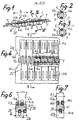
- the connecting device consists of a series of independent elements 1 in the general form of rod sections of circular section, which are arranged one after the other .
- These elements are made of a material with high mechanical resistance, for example steel or any other suitable metal. Their manufacture is carried out by cutting and stamping a profile of corresponding section. Consequently, these are massive and rigid elements.
- junction staples 2a and 2b can be fixed, on the two parts 3a and 3b of the conveyor belt, by cleats 5a and 5b made of metal wires, or by any other suitable member, for example rivets.
- the staples of each row are independent of each other or else initially connected to each other by a flexible element capable of becoming. break during use of the corresponding conveyor belt.
- each of the elements 1 of this device is very limited.
- this length L is at most equal to the total of the space occupied, in the transverse direction, by the two knuckles 4a of the junction clip 2a and the knuckles 4b of the clip 2b, which is located next to it.
- This length L therefore corresponds to the total of the width of these four knuckles and of the importance of the clearances provided therebetween.
- each of. these elements 1 is intended to ensure only the articulated connection of two clips 2a and 2b located opposite one another. This is to leave the staples of each row independent of each other.
- each of the elements 1 of this device comprises offset parts whose width corresponds to that of the respective respective knuckles 4a and 4b.
- each element 1 comprises four separate parts, offset from each other, namely: two parts 6a offset from two other parts 6b.
- the parts 6a are intended to be placed inside the knuckles 4a of a connecting clip 2a, while the parts 6b are arranged inside the knuckles 4b of the clip 2b located opposite.
- the clips 2a and 2b of the two rows take the respective positions shown in Figure 6, so that the junction elements 1 are prevented from being able to move in the transverse direction.
- the various elements 1 constituting the present device are initially connected by a temporary connection means.
- these are two rods 7 of flexible material which are engaged in longitudinal grooves 8 provided on the periphery of the elements 1.
- the different elements 1 form a unit in one piece which can be easily engaged inside the transverse conduit formed by the union of knuckles 4a and 4b of the two rows of junction staples.
- the device thus formed may include a terminal element l. Provided with a projecting head l h , the abutment of which, against the knuckle of the corresponding clip, determines the correct positioning of all of the various other elements 1, inside the knuckles 4a and 4b.
- each of the constituent elements 1 of this device is a solid element which can be made of a material of high mechanical resistance.
- the sides 20 of the shoulders, formed by the offset of the parts 6a and 6b, are inclined (see FIG. 6), so as to ensure a refocusing of each of the elements 1 of this connecting device with respect to the knuckles of each of the staples, when the junction produced is subjected to a tensile force when the corresponding conveyor belt is put into service.
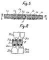
- Figures 7 and 8 show two other embodiments of the device according to the invention.
- the connecting element 11 shown is intended to ensure the connection of two series of junction staples 12a and 12b, one of which (12a) comprises a single knuckle 14a situated in the middle and intended to be placed between two spaced knuckles 14b provided on the clip 12b disposed opposite.
- the connecting elements 21 of the device according to the invention are each intended to ensure the connection of three knuckles 24a or 24b - belonging to two staples 22a or 22b, arranged opposite, and which each include two knuckles. In such a case, the clips of one and the other rows are offset.
- FIG. 9 illustrates another embodiment in which the temporary means for connecting the elements 1b of the corresponding device consists of a flexible wire 10 on which these elements are threaded. This wire has a very low mechanical resistance so as to break quickly when the corresponding conveyor belt is in service, so that the various elements 1b are now independent of each other, as in the first embodiment described.
- the presence of a channel in each of the elements 1b, to serve as a passage for the wire 10, is not such as to significantly reduce the mechanical resistance of these elements. Indeed, the channel thus provided has a very small section. There is therefore no real relationship with the connecting axes constituted by a cable made of twisted metal wires on which metal sleeves are threaded. Moreover, in the present case the wire 10 constitutes a simple temporary connection means intended to disappear as soon as the corresponding conveyor belt is put into service.
- FIG. 10 shows another embodiment in which the temporary connection means between the various elements lc of the corresponding device consists of a sheath 15 of flexible material, inside which these elements are housed one after the other. other.
- This sheath is made with a very small thickness and made of a material such that it is made to break as soon as the corresponding conveyor belt is put into service, so that the elements lc of this connecting device have complete independence from each other. to others, as well as to the embodiments previously described.
- FIG. 11 shows another embodiment in which the provisional connection of the various elements ld of this device is ensured by pins 16 provided at one end of each of them and provided with a bulge 17 constituting a ball joint intended to be engaged in a cavity formed in the opposite end of each element.
- pins 16 provided at one end of each of them and provided with a bulge 17 constituting a ball joint intended to be engaged in a cavity formed in the opposite end of each element.
- FIG. 13 represents a particular embodiment of the connection device according to the invention.
- the corresponding device is not formed, over its entire length, by a series of identical elements 1, la, lb, lc or ld of short length.
- this device comprises only two series of such elements le and If which are located in zones A and B where the corresponding conveyor belt will be caused to form an elbow when it is curved on the support rollers 9.
- the present device comprises a rigid axis 18 constituted by a rod of circular section of high mechanical strength.
- This device also includes two other similar axes 19, located on either side of the two series of elements le and lf.
- This particular structure allows the desired curving of the conveyor belt in the areas where it is caused to form an elbow when it is in service. In the other parts, it matters little that the connection of the connecting clips is ensured by rigid pins 18 and 19 since these are not caused to form an elbow or to curve when the conveyor belt is in service.
- the distribution of the flexible and rigid zones of such a connecting device could be modified according to the cases and applications.
- connection according to the invention is not limited to only the exemplary embodiments which have been described previously.
- the subject of the present invention is not only a connection device, as described above, but also the connection clips for conveyor belts which are formed by the combination of two rows of junction clips and of 'a connecting device as described above.
Landscapes
- Engineering & Computer Science (AREA)
- General Engineering & Computer Science (AREA)
- Mechanical Engineering (AREA)
- Belt Conveyors (AREA)
- Chain Conveyers (AREA)
Applications Claiming Priority (2)
| Application Number | Priority Date | Filing Date | Title |
|---|---|---|---|
| FR8418870 | 1984-12-11 | ||
| FR8418870A FR2574510B1 (fr) | 1984-12-11 | 1984-12-11 | Dispositif destine a assurer la liaison articulee de deux series complementaires d'agrafes de jonction |
Publications (2)
| Publication Number | Publication Date |
|---|---|
| EP0187061A1 true EP0187061A1 (de) | 1986-07-09 |
| EP0187061B1 EP0187061B1 (de) | 1989-03-15 |
Family
ID=9310449
Family Applications (1)
| Application Number | Title | Priority Date | Filing Date |
|---|---|---|---|
| EP85402234A Expired EP0187061B1 (de) | 1984-12-11 | 1985-11-19 | Vorrichtung zu einer gelenkigen Verbindung von zwei ergänzenden Reihen von Verbindungshaken |
Country Status (7)
| Country | Link |
|---|---|
| US (1) | US4641398A (de) |
| EP (1) | EP0187061B1 (de) |
| JP (1) | JPS61248809A (de) |
| CA (1) | CA1219834A (de) |
| DE (1) | DE3568843D1 (de) |
| FR (1) | FR2574510B1 (de) |
| ZA (1) | ZA858923B (de) |
Cited By (1)
| Publication number | Priority date | Publication date | Assignee | Title |
|---|---|---|---|---|
| CN109993375A (zh) * | 2019-04-23 | 2019-07-09 | 武汉智能装备工业技术研究院有限公司 | 一种智能选箱装箱包装线传送带长度设计方法 |
Families Citing this family (8)
| Publication number | Priority date | Publication date | Assignee | Title |
|---|---|---|---|---|
| FR2624940A1 (fr) * | 1987-12-17 | 1989-06-23 | Goro Sa | Axe de jonction pour l'accouplement des extremites d'un tapis transporteur ou similaire |
| DE68910694T2 (de) * | 1989-12-14 | 1994-05-05 | Goro Sa | Dichtung für die Verbindung von zwei Stücken eines Förderbandes und eine solche Dichtung aufweisende Verbindung. |
| FR2664009B1 (fr) * | 1990-06-27 | 1995-07-13 | Goro Sa | Agrafes pour la jonction des extremites d'un tapis transporteur et appareil pour la fixation de telles agrafes. |
| DE4416079C2 (de) * | 1994-02-02 | 1997-06-26 | Mato Masch & Metallwaren | Kupplungsstab |
| GB2286171B (en) * | 1994-02-02 | 1997-07-16 | Mato Masch & Metallwaren | Coupling bar for conveyor belt |
| DE19531432A1 (de) * | 1995-08-27 | 1997-03-06 | Mato Masch & Metallwaren | Förderband zur Verwendung in einer Fördervorrichtung mit einer Muldungszone |
| DE19702005A1 (de) * | 1997-01-22 | 1998-07-23 | Goro Sa | Kupplungsstab |
| TWI231733B (en) * | 2004-03-29 | 2005-04-21 | Benq Corp | Shaft apparatus with a shielding function |
Citations (9)
| Publication number | Priority date | Publication date | Assignee | Title |
|---|---|---|---|---|
| BE368962A (de) * | ||||
| GB128169A (en) * | 1919-04-07 | 1919-06-19 | Stanley Thomas Robson | Improvements in Belt Fasteners. |
| FR720857A (fr) * | 1930-11-05 | 1932-02-25 | Supplex Ets | Perfectionnements aux baguettes charnières utilisées comme chevilles axiales dans la liaison des extrémités d'un ou de plusieurs éléments formant attaches de courroies |
| DE805144C (de) * | 1948-10-02 | 1951-05-07 | Paul Werver Kom Ges Inh Hans Z | Bandnadel fuer Drahthakenverbindungen an Foerdergurten o. dgl. |
| DE926645C (de) * | 1952-06-19 | 1955-04-21 | Hugo Timmerbeil Fa | Riemenverbinder |
| US2962782A (en) * | 1957-12-09 | 1960-12-06 | Flexible Steel Lacing Co | Hinge pin |
| FR2196683A5 (de) * | 1972-08-14 | 1974-03-15 | Matthaei Mato Masch | |
| FR2301738A1 (fr) * | 1975-02-21 | 1976-09-17 | Matthaei Mato Masch | Barre de jonction pour reunir les extremites de bandes transporteuses |
| FR2380471A1 (fr) * | 1977-02-15 | 1978-09-08 | Kuester W H Gmbh Co Kg | Axe de jonction servant a relier les extremites de convoyeurs a courroie |
Family Cites Families (8)
| Publication number | Priority date | Publication date | Assignee | Title |
|---|---|---|---|---|
| US1157499A (en) * | 1912-09-16 | 1915-10-19 | U S Light And Heat Corp | Belt and belt-fastener. |
| US1813311A (en) * | 1929-01-11 | 1931-07-07 | Mark Frederick Higgins | Conveyer belt |
| US1975862A (en) * | 1933-04-26 | 1934-10-09 | Flexible Steel Lacing Co | Hinged fastening |
| US2069385A (en) * | 1935-04-12 | 1937-02-02 | Flexible Steel Lacing Co | Belt fastener |
| US2145455A (en) * | 1937-10-05 | 1939-01-31 | Flexible Steel Lacing Co | Flexible belt fastener |
| US2272527A (en) * | 1940-11-29 | 1942-02-10 | Bristol Company | Belt fastener |
| US2490195A (en) * | 1945-10-29 | 1949-12-06 | Flexible Steel Lacing Co | V-belt fastener |
| DE1218816B (de) * | 1963-09-24 | 1966-06-08 | Wiese Hans Holger | Verbindungsschloss fuer Baender aus Gummi oder Kunststoff |
-
1984
- 1984-12-11 FR FR8418870A patent/FR2574510B1/fr not_active Expired
-
1985
- 1985-11-18 US US06/799,723 patent/US4641398A/en not_active Expired - Fee Related
- 1985-11-19 EP EP85402234A patent/EP0187061B1/de not_active Expired
- 1985-11-19 DE DE8585402234T patent/DE3568843D1/de not_active Expired
- 1985-11-20 ZA ZA858923A patent/ZA858923B/xx unknown
- 1985-11-27 CA CA000496348A patent/CA1219834A/en not_active Expired
- 1985-12-11 JP JP60278835A patent/JPS61248809A/ja active Pending
Patent Citations (9)
| Publication number | Priority date | Publication date | Assignee | Title |
|---|---|---|---|---|
| BE368962A (de) * | ||||
| GB128169A (en) * | 1919-04-07 | 1919-06-19 | Stanley Thomas Robson | Improvements in Belt Fasteners. |
| FR720857A (fr) * | 1930-11-05 | 1932-02-25 | Supplex Ets | Perfectionnements aux baguettes charnières utilisées comme chevilles axiales dans la liaison des extrémités d'un ou de plusieurs éléments formant attaches de courroies |
| DE805144C (de) * | 1948-10-02 | 1951-05-07 | Paul Werver Kom Ges Inh Hans Z | Bandnadel fuer Drahthakenverbindungen an Foerdergurten o. dgl. |
| DE926645C (de) * | 1952-06-19 | 1955-04-21 | Hugo Timmerbeil Fa | Riemenverbinder |
| US2962782A (en) * | 1957-12-09 | 1960-12-06 | Flexible Steel Lacing Co | Hinge pin |
| FR2196683A5 (de) * | 1972-08-14 | 1974-03-15 | Matthaei Mato Masch | |
| FR2301738A1 (fr) * | 1975-02-21 | 1976-09-17 | Matthaei Mato Masch | Barre de jonction pour reunir les extremites de bandes transporteuses |
| FR2380471A1 (fr) * | 1977-02-15 | 1978-09-08 | Kuester W H Gmbh Co Kg | Axe de jonction servant a relier les extremites de convoyeurs a courroie |
Cited By (1)
| Publication number | Priority date | Publication date | Assignee | Title |
|---|---|---|---|---|
| CN109993375A (zh) * | 2019-04-23 | 2019-07-09 | 武汉智能装备工业技术研究院有限公司 | 一种智能选箱装箱包装线传送带长度设计方法 |
Also Published As
| Publication number | Publication date |
|---|---|
| DE3568843D1 (en) | 1989-04-20 |
| CA1219834A (en) | 1987-03-31 |
| US4641398A (en) | 1987-02-10 |
| EP0187061B1 (de) | 1989-03-15 |
| FR2574510B1 (fr) | 1987-01-09 |
| FR2574510A1 (fr) | 1986-06-13 |
| JPS61248809A (ja) | 1986-11-06 |
| ZA858923B (en) | 1986-07-30 |
Similar Documents
| Publication | Publication Date | Title |
|---|---|---|
| EP0166645B1 (de) | Biegsame Achse zur beweglichen Verbindung von hakenartigen Transportriemenschlössern | |
| FR2713492A1 (fr) | Guide tubulaire orientable, notamment pour un dispositif médico-chirurgical. | |
| FR2652131A1 (fr) | Piece plate ayant la faculte d'etirement elastique dans la direction longitudinale, son procede de fabrication et son application a un collier de serrage. | |
| FR2552851A1 (fr) | Embouts destines a etre fixes aux extremites d'un conduit flexible, pour constituer un raccord utilisable sur une pompe portative pour le gonflage de pneumatiques, et raccord comportant de tels embouts | |
| EP0187061B1 (de) | Vorrichtung zu einer gelenkigen Verbindung von zwei ergänzenden Reihen von Verbindungshaken | |
| FR2524408A1 (fr) | Assemblages de balais d'essuie-glace | |
| FR2706834A1 (de) | ||
| EP1310717B1 (de) | Spannband | |
| FR2685614A1 (fr) | Bracelet a maillons notamment pour montre. | |
| EP0191667A1 (de) | Kabelrinne aus Drahtgitter | |
| EP0324290B1 (de) | Kupplungsstab zum Verbinden der Enden eines Transportbandes oder dgl. | |
| EP0209452B1 (de) | Mehrzweck-Steckverbinder für das Anschliessen von verschiedenen Kabeltypen oder elektrischer Leiter | |
| FR2619292A1 (fr) | Fermoir pour bracelet | |
| EP0132208A1 (de) | Abspannklemme für isolierte Tragseile mit mehreren Leitern | |
| FR2518192A1 (fr) | Dispositif d'assemblage de deux pieces, telles que deux profiles realises par exemple en alliage leger | |
| EP0146471B1 (de) | Verfahren und Vorrichtung zur halbpermanenten Verbindung von optischen Fasern | |
| FR2626723A1 (fr) | Dispositif deformable pour relier des conduits de distribution d'energie electrique | |
| EP0744088B1 (de) | Elektrischer stecker in englischer ausführung | |
| FR2754639A1 (fr) | Procede de fabrication d'un contact femelle de raccordement electrique et contact obtenu par un tel procede | |
| FR2633402A1 (fr) | Conducteur optique resistant a la traction | |
| FR2732083A1 (fr) | Dispositif de connexion a montage simplifie pour assembler deux profiles | |
| FR2493585A1 (fr) | Ligature preformee pour la retenue d'un conducteur dans la gorge d'un isolateur rigide | |
| FR2555677A1 (fr) | Collier de serrage de faisceau de cables | |
| EP0156714A1 (de) | Alignement- und Verbindungsvorrichtung für Profile, insbesondere in Kunststoff, für die Realisierung von Spalieren und Verfahren für deren Verwendung | |
| CH703096A2 (fr) | Bracelet a maillons articules. |
Legal Events
| Date | Code | Title | Description |
|---|---|---|---|
| PUAI | Public reference made under article 153(3) epc to a published international application that has entered the european phase |
Free format text: ORIGINAL CODE: 0009012 |
|
| AK | Designated contracting states |
Kind code of ref document: A1 Designated state(s): BE DE GB IT |
|
| 17P | Request for examination filed |
Effective date: 19861208 |
|
| 17Q | First examination report despatched |
Effective date: 19880616 |
|
| GRAA | (expected) grant |
Free format text: ORIGINAL CODE: 0009210 |
|
| AK | Designated contracting states |
Kind code of ref document: B1 Designated state(s): BE DE GB IT |
|
| GBT | Gb: translation of ep patent filed (gb section 77(6)(a)/1977) | ||
| REF | Corresponds to: |
Ref document number: 3568843 Country of ref document: DE Date of ref document: 19890420 |
|
| ITF | It: translation for a ep patent filed | ||
| PGFP | Annual fee paid to national office [announced via postgrant information from national office to epo] |
Ref country code: BE Payment date: 19891115 Year of fee payment: 5 |
|
| PLBE | No opposition filed within time limit |
Free format text: ORIGINAL CODE: 0009261 |
|
| STAA | Information on the status of an ep patent application or granted ep patent |
Free format text: STATUS: NO OPPOSITION FILED WITHIN TIME LIMIT |
|
| 26N | No opposition filed | ||
| PGFP | Annual fee paid to national office [announced via postgrant information from national office to epo] |
Ref country code: GB Payment date: 19901119 Year of fee payment: 6 |
|
| PGFP | Annual fee paid to national office [announced via postgrant information from national office to epo] |
Ref country code: DE Payment date: 19901129 Year of fee payment: 6 |
|
| ITTA | It: last paid annual fee | ||
| PG25 | Lapsed in a contracting state [announced via postgrant information from national office to epo] |
Ref country code: BE Effective date: 19901130 |
|
| BERE | Be: lapsed |
Owner name: S.A GORO Effective date: 19901130 |
|
| PG25 | Lapsed in a contracting state [announced via postgrant information from national office to epo] |
Ref country code: GB Effective date: 19911119 |
|
| GBPC | Gb: european patent ceased through non-payment of renewal fee | ||
| PG25 | Lapsed in a contracting state [announced via postgrant information from national office to epo] |
Ref country code: DE Effective date: 19920801 |