EP0187099A1 - Zylinderkopf für eine Brennkraftmaschine - Google Patents
Zylinderkopf für eine Brennkraftmaschine Download PDFInfo
- Publication number
- EP0187099A1 EP0187099A1 EP85402551A EP85402551A EP0187099A1 EP 0187099 A1 EP0187099 A1 EP 0187099A1 EP 85402551 A EP85402551 A EP 85402551A EP 85402551 A EP85402551 A EP 85402551A EP 0187099 A1 EP0187099 A1 EP 0187099A1
- Authority
- EP
- European Patent Office
- Prior art keywords
- cylinder head
- plane
- centered
- cylinder
- intake
- Prior art date
- Legal status (The legal status is an assumption and is not a legal conclusion. Google has not performed a legal analysis and makes no representation as to the accuracy of the status listed.)
- Withdrawn
Links
- 238000002485 combustion reaction Methods 0.000 title claims description 11
- 238000002347 injection Methods 0.000 claims description 15
- 239000007924 injection Substances 0.000 claims description 15
- 230000006835 compression Effects 0.000 claims description 11
- 238000007906 compression Methods 0.000 claims description 11
- 238000001816 cooling Methods 0.000 claims description 5
- 239000002826 coolant Substances 0.000 claims description 4
- 239000007788 liquid Substances 0.000 claims description 3
- 238000005266 casting Methods 0.000 claims description 2
- 238000004519 manufacturing process Methods 0.000 abstract description 4
- 238000009826 distribution Methods 0.000 abstract description 2
- 238000009434 installation Methods 0.000 description 5
- 230000008901 benefit Effects 0.000 description 4
- XLYOFNOQVPJJNP-UHFFFAOYSA-N water Substances O XLYOFNOQVPJJNP-UHFFFAOYSA-N 0.000 description 2
- 230000001133 acceleration Effects 0.000 description 1
- 229910052782 aluminium Inorganic materials 0.000 description 1
- XAGFODPZIPBFFR-UHFFFAOYSA-N aluminium Chemical compound [Al] XAGFODPZIPBFFR-UHFFFAOYSA-N 0.000 description 1
- 230000001143 conditioned effect Effects 0.000 description 1
- 238000010276 construction Methods 0.000 description 1
- 239000000446 fuel Substances 0.000 description 1
- 239000000463 material Substances 0.000 description 1
- 229910052751 metal Inorganic materials 0.000 description 1
- 239000002184 metal Substances 0.000 description 1
- 239000000203 mixture Substances 0.000 description 1
- 238000012986 modification Methods 0.000 description 1
- 230000004048 modification Effects 0.000 description 1
Images

Classifications
-
- F—MECHANICAL ENGINEERING; LIGHTING; HEATING; WEAPONS; BLASTING
- F02—COMBUSTION ENGINES; HOT-GAS OR COMBUSTION-PRODUCT ENGINE PLANTS
- F02F—CYLINDERS, PISTONS OR CASINGS, FOR COMBUSTION ENGINES; ARRANGEMENTS OF SEALINGS IN COMBUSTION ENGINES
- F02F1/00—Cylinders; Cylinder heads
- F02F1/24—Cylinder heads
- F02F1/42—Shape or arrangement of intake or exhaust channels in cylinder heads
- F02F1/4214—Shape or arrangement of intake or exhaust channels in cylinder heads specially adapted for four or more valves per cylinder
-
- F—MECHANICAL ENGINEERING; LIGHTING; HEATING; WEAPONS; BLASTING
- F02—COMBUSTION ENGINES; HOT-GAS OR COMBUSTION-PRODUCT ENGINE PLANTS
- F02B—INTERNAL-COMBUSTION PISTON ENGINES; COMBUSTION ENGINES IN GENERAL
- F02B1/00—Engines characterised by fuel-air mixture compression
- F02B1/02—Engines characterised by fuel-air mixture compression with positive ignition
- F02B1/04—Engines characterised by fuel-air mixture compression with positive ignition with fuel-air mixture admission into cylinder
-
- F—MECHANICAL ENGINEERING; LIGHTING; HEATING; WEAPONS; BLASTING
- F02—COMBUSTION ENGINES; HOT-GAS OR COMBUSTION-PRODUCT ENGINE PLANTS
- F02B—INTERNAL-COMBUSTION PISTON ENGINES; COMBUSTION ENGINES IN GENERAL
- F02B2275/00—Other engines, components or details, not provided for in other groups of this subclass
- F02B2275/16—Indirect injection
-
- F—MECHANICAL ENGINEERING; LIGHTING; HEATING; WEAPONS; BLASTING
- F02—COMBUSTION ENGINES; HOT-GAS OR COMBUSTION-PRODUCT ENGINE PLANTS
- F02B—INTERNAL-COMBUSTION PISTON ENGINES; COMBUSTION ENGINES IN GENERAL
- F02B2275/00—Other engines, components or details, not provided for in other groups of this subclass
- F02B2275/20—SOHC [Single overhead camshaft]
-
- F—MECHANICAL ENGINEERING; LIGHTING; HEATING; WEAPONS; BLASTING
- F02—COMBUSTION ENGINES; HOT-GAS OR COMBUSTION-PRODUCT ENGINE PLANTS
- F02B—INTERNAL-COMBUSTION PISTON ENGINES; COMBUSTION ENGINES IN GENERAL
- F02B3/00—Engines characterised by air compression and subsequent fuel addition
- F02B3/06—Engines characterised by air compression and subsequent fuel addition with compression ignition
-
- F—MECHANICAL ENGINEERING; LIGHTING; HEATING; WEAPONS; BLASTING
- F02—COMBUSTION ENGINES; HOT-GAS OR COMBUSTION-PRODUCT ENGINE PLANTS
- F02F—CYLINDERS, PISTONS OR CASINGS, FOR COMBUSTION ENGINES; ARRANGEMENTS OF SEALINGS IN COMBUSTION ENGINES
- F02F1/00—Cylinders; Cylinder heads
- F02F1/24—Cylinder heads
- F02F2001/244—Arrangement of valve stems in cylinder heads
- F02F2001/247—Arrangement of valve stems in cylinder heads the valve stems being orientated in parallel with the cylinder axis
-
- Y—GENERAL TAGGING OF NEW TECHNOLOGICAL DEVELOPMENTS; GENERAL TAGGING OF CROSS-SECTIONAL TECHNOLOGIES SPANNING OVER SEVERAL SECTIONS OF THE IPC; TECHNICAL SUBJECTS COVERED BY FORMER USPC CROSS-REFERENCE ART COLLECTIONS [XRACs] AND DIGESTS
- Y02—TECHNOLOGIES OR APPLICATIONS FOR MITIGATION OR ADAPTATION AGAINST CLIMATE CHANGE
- Y02T—CLIMATE CHANGE MITIGATION TECHNOLOGIES RELATED TO TRANSPORTATION
- Y02T10/00—Road transport of goods or passengers
- Y02T10/10—Internal combustion engine [ICE] based vehicles
- Y02T10/12—Improving ICE efficiencies
Definitions
- the present invention relates to an internal combustion engine cylinder head which is particularly well suited to all types of mass market engines.
- Its purpose is to propose a particular architecture of cylinder head which is versatile, that is to say which requires only minor modifications to pass from one combustion process to another (spark-ignition, compression-ignition engines and direct injection, and compression ignition and indirect injection).
- a cylinder head of the type receiving two intake valves and one exhaust valve per cylinder, actuated by respective latches mounted on ball joints.
- the exhaust valve is centered on the axial plane of the cylinder which is perpendicular to the longitudinal plane of the engine, and designated transverse plane, and the two intake valves are centered on a plane parallel to this. longitudinal plane, symmetrically to this transverse plane.
- the exhaust latch is centered on the transverse plane, and the two intake lugs are respectively centered on two intersecting planes, symmetrical with respect to this transverse plane, and passing through the axes of the respective intake valves.
- the three valves are controlled by a single camshaft, arranged parallel to the longitudinal plane of the engine, above the catches which it actuates.
- the intake valves of two contiguous cylinders are supplied by a fork conduit whose common branch is centered on an inter-cylinder plane, each extreme intake valve by a unitary conduit in the form half fork, and each exhaust valve by a conduit centered on the transverse plane of the corresponding cylinder.
- the invention proposes to use, to improve the filling of so-called “supercarred” engines, two intake valves and one exhaust per cylinder. This is well known to those skilled in the art, but the arrangement and control of these valves according to the description below are particularly recommended for engines of wide distribution and therefore at limited cost price.
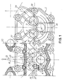
- a single camshaft controls two intake valves 2, 2 ′ and an exhaust valve 4 per cylinder, inside this cylinder head 1.
- valves 2, 2 'and 4 are actuated by latches 6, 6' and 8 bearing on hydraulic ball joints or not. These have a high rigidity, thus offering the possibility of using laws of movement of valves with high acceleration to increase the filling.
- the camshaft to simplify the production of the cylinder head, is housed in a special housing, not shown, forming the cylinder head cover. It is positioned parallel to the axis of the crankshaft, above the latches that it actuates, and between the intake and exhaust valves to suitably satisfy their control kinematics.
- the best relative dimensioning for these valves and for a given bore leads to aligning the intake valves 2, 2 ′ on a plane 14 slightly set back from the longitudinal plane 10 of the row of engine cylinders and symmetrically to the transverse plane 12 of the corresponding cylinder, and to center the exhaust valve 4 on this transverse plane.
- This plane 12 is the axial plane of the cylinder which is perpendicular to the longitudinal plane 10 of the engine.
- This arrangement provides inter-seats (valves 2, 2 '/ valve 4) compatible with good behavior of the cylinder head material (aluminum for loaded engines).
- the two intake latches 6, 6 ' are respectively centered on two intersecting planes 16, 18, symmetrical with respect to the transverse plane 12, and passing through the axes of the respective valves 2, 2'. This slight divergence allows the support ball joints of these lugs 6, 6 ′ to be put in place with respect to the not shown spring of the exhaust valve 4. In addition, in order to avoid tilting the latch, it implies the use of a control cam whose width can ensure the entire range of this latch.
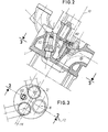
- the intake valves 2, 2 ′ of two contiguous cylinders are supplied by a fork duct 20, the common branch of which is centered on an inter-cylinder plane 22.
- the end valves of the end cylinders are supplied by unitary ducts 24 each represented by a half-fork.
- This arrangement makes it possible to easily obtain, using an appropriate manifold, the filling of the cylinders with fuel mixture by one or two valves.
- This is a known and very advantageous advantage for positive-ignition engines subjected to variations in load and speed when they are used to propel vehicles in particular.
- Each exhaust valve 4 is associated with a conduit 26 centered on the transverse plane 12 of the corresponding cylinder.
- This arrangement of conduits allows a remarkable arrangement of screws 28 for fixing the cylinder head to the crankcase.
- Each cylinder can be fitted with four circumscribed screws, the longitudinal pitch of which remains small.
- an additional screw 30 can be provided at the intersection of the longitudinal planes 10 and inter-cylinders 22, as well as at the ends of the cylinder head. The tightening of the cylinder head 1 is thus carried out with six screws distributed in a substantially regular manner around each cylinder.
- the good behavior of the head gasket is obtained without artifices; the parts can be lighter and the screws more lightly dimensioned.
- the cylinder head gasket does not require retightening, the inter-cylinder screws 30 may be inaccessible, once the cylinder head cover is in place.
- This arrangement proves to be particularly advantageous for engines which have a large cylinder axis conditioned by the dimensioning of the crankshaft (for example six-cylinder V-shaped engines with equidistant combustions).
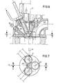
- valves 2, 2 ′, 4 and their control device described above has the advantage of offering a large free space opposite the exhaust valve 4; he It is therefore possible to install there in the best conditions, ignition or injection means depending on the type of engine selected.
- the corresponding injector 36 will benefit from the prechamber, the best possible tilt, like the spark plug 32 in the case of the spark ignition engine.
- This inclination is dictated, as for the installation of the spark plug 32, by the upper part of the cylinder head ( Figure 6).
- a cooling mode common to these three types of cylinder head, will comprise a longitudinal ramp 40 supplied directly by the liquid circulating in the cylinder block as soon as it exits under pressure from the water pump.
- the coolant can arrive at a high flow rate at the bottom of the well corresponding to the "heat rectangle", and comes out only after having licked all the walls heated by conduction from the sole of the cylinder head.
Landscapes
- Engineering & Computer Science (AREA)
- Chemical & Material Sciences (AREA)
- Combustion & Propulsion (AREA)
- Mechanical Engineering (AREA)
- General Engineering & Computer Science (AREA)
- Valve-Gear Or Valve Arrangements (AREA)
- Cylinder Crankcases Of Internal Combustion Engines (AREA)
Applications Claiming Priority (2)
| Application Number | Priority Date | Filing Date | Title |
|---|---|---|---|
| FR8419619A FR2575226B1 (fr) | 1984-12-21 | 1984-12-21 | Culasse de moteur a combustion interne |
| FR8419619 | 1984-12-21 |
Publications (1)
| Publication Number | Publication Date |
|---|---|
| EP0187099A1 true EP0187099A1 (de) | 1986-07-09 |
Family
ID=9310870
Family Applications (1)
| Application Number | Title | Priority Date | Filing Date |
|---|---|---|---|
| EP85402551A Withdrawn EP0187099A1 (de) | 1984-12-21 | 1985-12-19 | Zylinderkopf für eine Brennkraftmaschine |
Country Status (3)
| Country | Link |
|---|---|
| EP (1) | EP0187099A1 (de) |
| ES (1) | ES8702982A1 (de) |
| FR (1) | FR2575226B1 (de) |
Cited By (5)
| Publication number | Priority date | Publication date | Assignee | Title |
|---|---|---|---|---|
| GB2266923A (en) * | 1992-05-07 | 1993-11-17 | Rover Group | Internal combustion engine fuel supply. |
| EP0894956A3 (de) * | 1997-08-01 | 1999-11-03 | C.R.F. Società Consortile per Azioni | Ottobrennkraftmaschine mit Brennkammer mit drei Ventilen und zentraler Zündkerze |
| CN119754958A (zh) * | 2024-12-26 | 2025-04-04 | 东风商用车有限公司 | 一种弧形对中跨缸直气道气缸盖及燃气发动机 |
| CN119754959A (zh) * | 2024-12-26 | 2025-04-04 | 东风商用车有限公司 | 一种直对中跨缸直气道缸盖及燃气发动机 |
| CN119754956A (zh) * | 2024-12-26 | 2025-04-04 | 东风商用车有限公司 | 一种基于跨缸气道的mpi供给系统 |
Citations (4)
| Publication number | Priority date | Publication date | Assignee | Title |
|---|---|---|---|---|
| US1915237A (en) * | 1933-03-01 | 1933-06-20 | Gen Airmotors Company | Internal combustion engine |
| FR853700A (fr) * | 1938-05-10 | 1940-03-26 | Automobili Isotta Fraschini Fa | Culasse pour moteurs à explosions polycylindriques à cylindre en ligne |
| FR1469325A (fr) * | 1966-02-05 | 1967-02-10 | Moteur Moderne Le | Dispositif spécial concernant l'admission des moteurs alternatifs à combustion interne |
| EP0062143A2 (de) * | 1981-04-02 | 1982-10-13 | Bayerische Motoren Werke Aktiengesellschaft, Patentabteilung AJ-3 | Zylinderkopf für luftverdichtende, selbstzündende Einspritz-Brennkraftmaschinen |
-
1984
- 1984-12-21 FR FR8419619A patent/FR2575226B1/fr not_active Expired
-
1985
- 1985-12-19 EP EP85402551A patent/EP0187099A1/de not_active Withdrawn
- 1985-12-20 ES ES550247A patent/ES8702982A1/es not_active Expired
Patent Citations (4)
| Publication number | Priority date | Publication date | Assignee | Title |
|---|---|---|---|---|
| US1915237A (en) * | 1933-03-01 | 1933-06-20 | Gen Airmotors Company | Internal combustion engine |
| FR853700A (fr) * | 1938-05-10 | 1940-03-26 | Automobili Isotta Fraschini Fa | Culasse pour moteurs à explosions polycylindriques à cylindre en ligne |
| FR1469325A (fr) * | 1966-02-05 | 1967-02-10 | Moteur Moderne Le | Dispositif spécial concernant l'admission des moteurs alternatifs à combustion interne |
| EP0062143A2 (de) * | 1981-04-02 | 1982-10-13 | Bayerische Motoren Werke Aktiengesellschaft, Patentabteilung AJ-3 | Zylinderkopf für luftverdichtende, selbstzündende Einspritz-Brennkraftmaschinen |
Cited By (6)
| Publication number | Priority date | Publication date | Assignee | Title |
|---|---|---|---|---|
| GB2266923A (en) * | 1992-05-07 | 1993-11-17 | Rover Group | Internal combustion engine fuel supply. |
| GB2266923B (en) * | 1992-05-07 | 1995-07-19 | Rover Group | Internal combustion engine fuel supply |
| EP0894956A3 (de) * | 1997-08-01 | 1999-11-03 | C.R.F. Società Consortile per Azioni | Ottobrennkraftmaschine mit Brennkammer mit drei Ventilen und zentraler Zündkerze |
| CN119754958A (zh) * | 2024-12-26 | 2025-04-04 | 东风商用车有限公司 | 一种弧形对中跨缸直气道气缸盖及燃气发动机 |
| CN119754959A (zh) * | 2024-12-26 | 2025-04-04 | 东风商用车有限公司 | 一种直对中跨缸直气道缸盖及燃气发动机 |
| CN119754956A (zh) * | 2024-12-26 | 2025-04-04 | 东风商用车有限公司 | 一种基于跨缸气道的mpi供给系统 |
Also Published As
| Publication number | Publication date |
|---|---|
| ES550247A0 (es) | 1987-01-16 |
| FR2575226B1 (fr) | 1987-02-13 |
| FR2575226A1 (fr) | 1986-06-27 |
| ES8702982A1 (es) | 1987-01-16 |
Similar Documents
| Publication | Publication Date | Title |
|---|---|---|
| US12202566B2 (en) | Straddled vehicle | |
| EP0125178A1 (de) | Kolben aus feuerfestem Material, insbesondere für Dieselbrennkraftmaschinen | |
| EP0187099A1 (de) | Zylinderkopf für eine Brennkraftmaschine | |
| JPS61108818A (ja) | エンジンの潤滑装置 | |
| EP0293278B1 (de) | Multiventil-Zylinderkopf für Brennkraftmaschine | |
| FR2683263A1 (fr) | Moteur a combustion interne avec circuit de refroidissement perfectionne. | |
| US3527263A (en) | Rocker shaft support with fuel nozzle supporting means | |
| FR2562162A1 (fr) | Culasse pour moteur a combustion interne a trois soupapes | |
| FR2774635A1 (fr) | Dispositif de refroidissement du carburant d'un moteur de vehicule automobile | |
| JPH0159410B2 (de) | ||
| FR2660694A1 (fr) | Moteur a combustion interne comprenant un circuit de refroidissement perfectionne. | |
| CH642143A5 (en) | Intake/exhaust unit for a four-stroke internal combustion engine | |
| US20220333522A1 (en) | Multiple cylinder engine | |
| EP0251835B1 (de) | Zylinderkopf für eine Brennkraftmaschine mit drei Ventilen pro Zylinder und mit hohem Druck in den Zylindern | |
| JP2548528B2 (ja) | 自動二輪車用4サイクル内燃機関 | |
| EP1135587A1 (de) | Zylinderkopf für eine flüssigkeitsgekühlte brennkraftmaschine | |
| JPH04255563A (ja) | V型2サイクルエンジン | |
| FR2484534A1 (fr) | Moteur a combustion interne perfectionne | |
| JPH0429077Y2 (de) | ||
| JPS603984Y2 (ja) | 多気筒デイ−ゼルエンジン | |
| FR2470257A1 (fr) | Moteur a combustion interne perfectionne | |
| JP2987734B2 (ja) | 縦型ガソリンエンジンの燃料供給装置 | |
| FR2727466A1 (fr) | Collecteur d'echappement pour moteur a combustion interne | |
| JPH0116982B2 (de) | ||
| BE423747A (de) |
Legal Events
| Date | Code | Title | Description |
|---|---|---|---|
| PUAI | Public reference made under article 153(3) epc to a published international application that has entered the european phase |
Free format text: ORIGINAL CODE: 0009012 |
|
| 17P | Request for examination filed |
Effective date: 19851227 |
|
| AK | Designated contracting states |
Kind code of ref document: A1 Designated state(s): AT DE GB IT SE |
|
| 17Q | First examination report despatched |
Effective date: 19870723 |
|
| STAA | Information on the status of an ep patent application or granted ep patent |
Free format text: STATUS: THE APPLICATION IS DEEMED TO BE WITHDRAWN |
|
| 18D | Application deemed to be withdrawn |
Effective date: 19871102 |
|
| RIN1 | Information on inventor provided before grant (corrected) |
Inventor name: DELEPLACE, CHRISTIAN |