EP0251835B1 - Zylinderkopf für eine Brennkraftmaschine mit drei Ventilen pro Zylinder und mit hohem Druck in den Zylindern - Google Patents
Zylinderkopf für eine Brennkraftmaschine mit drei Ventilen pro Zylinder und mit hohem Druck in den Zylindern Download PDFInfo
- Publication number
- EP0251835B1 EP0251835B1 EP87401175A EP87401175A EP0251835B1 EP 0251835 B1 EP0251835 B1 EP 0251835B1 EP 87401175 A EP87401175 A EP 87401175A EP 87401175 A EP87401175 A EP 87401175A EP 0251835 B1 EP0251835 B1 EP 0251835B1
- Authority
- EP
- European Patent Office
- Prior art keywords
- cylinder head
- cylinder
- plane
- axis
- induction
- Prior art date
- Legal status (The legal status is an assumption and is not a legal conclusion. Google has not performed a legal analysis and makes no representation as to the accuracy of the status listed.)
- Expired
Links
- 238000002485 combustion reaction Methods 0.000 title claims abstract description 10
- 230000006698 induction Effects 0.000 claims abstract 18
- 230000006835 compression Effects 0.000 description 2
- 238000007906 compression Methods 0.000 description 2
- 238000009434 installation Methods 0.000 description 2
Images


Classifications
-
- F—MECHANICAL ENGINEERING; LIGHTING; HEATING; WEAPONS; BLASTING
- F02—COMBUSTION ENGINES; HOT-GAS OR COMBUSTION-PRODUCT ENGINE PLANTS
- F02F—CYLINDERS, PISTONS OR CASINGS, FOR COMBUSTION ENGINES; ARRANGEMENTS OF SEALINGS IN COMBUSTION ENGINES
- F02F1/00—Cylinders; Cylinder heads
- F02F1/24—Cylinder heads
- F02F1/42—Shape or arrangement of intake or exhaust channels in cylinder heads
- F02F1/4214—Shape or arrangement of intake or exhaust channels in cylinder heads specially adapted for four or more valves per cylinder
-
- F—MECHANICAL ENGINEERING; LIGHTING; HEATING; WEAPONS; BLASTING
- F02—COMBUSTION ENGINES; HOT-GAS OR COMBUSTION-PRODUCT ENGINE PLANTS
- F02B—INTERNAL-COMBUSTION PISTON ENGINES; COMBUSTION ENGINES IN GENERAL
- F02B19/00—Engines characterised by precombustion chambers
- F02B19/14—Engines characterised by precombustion chambers with compression ignition
-
- F—MECHANICAL ENGINEERING; LIGHTING; HEATING; WEAPONS; BLASTING
- F02—COMBUSTION ENGINES; HOT-GAS OR COMBUSTION-PRODUCT ENGINE PLANTS
- F02B—INTERNAL-COMBUSTION PISTON ENGINES; COMBUSTION ENGINES IN GENERAL
- F02B2275/00—Other engines, components or details, not provided for in other groups of this subclass
- F02B2275/10—Diamond configuration of valves in cylinder heads
-
- F—MECHANICAL ENGINEERING; LIGHTING; HEATING; WEAPONS; BLASTING
- F02—COMBUSTION ENGINES; HOT-GAS OR COMBUSTION-PRODUCT ENGINE PLANTS
- F02B—INTERNAL-COMBUSTION PISTON ENGINES; COMBUSTION ENGINES IN GENERAL
- F02B2275/00—Other engines, components or details, not provided for in other groups of this subclass
- F02B2275/16—Indirect injection
-
- F—MECHANICAL ENGINEERING; LIGHTING; HEATING; WEAPONS; BLASTING
- F02—COMBUSTION ENGINES; HOT-GAS OR COMBUSTION-PRODUCT ENGINE PLANTS
- F02B—INTERNAL-COMBUSTION PISTON ENGINES; COMBUSTION ENGINES IN GENERAL
- F02B2275/00—Other engines, components or details, not provided for in other groups of this subclass
- F02B2275/20—SOHC [Single overhead camshaft]
-
- F—MECHANICAL ENGINEERING; LIGHTING; HEATING; WEAPONS; BLASTING
- F02—COMBUSTION ENGINES; HOT-GAS OR COMBUSTION-PRODUCT ENGINE PLANTS
- F02B—INTERNAL-COMBUSTION PISTON ENGINES; COMBUSTION ENGINES IN GENERAL
- F02B3/00—Engines characterised by air compression and subsequent fuel addition
- F02B3/06—Engines characterised by air compression and subsequent fuel addition with compression ignition
-
- F—MECHANICAL ENGINEERING; LIGHTING; HEATING; WEAPONS; BLASTING
- F02—COMBUSTION ENGINES; HOT-GAS OR COMBUSTION-PRODUCT ENGINE PLANTS
- F02F—CYLINDERS, PISTONS OR CASINGS, FOR COMBUSTION ENGINES; ARRANGEMENTS OF SEALINGS IN COMBUSTION ENGINES
- F02F1/00—Cylinders; Cylinder heads
- F02F1/24—Cylinder heads
- F02F2001/244—Arrangement of valve stems in cylinder heads
- F02F2001/247—Arrangement of valve stems in cylinder heads the valve stems being orientated in parallel with the cylinder axis
-
- Y—GENERAL TAGGING OF NEW TECHNOLOGICAL DEVELOPMENTS; GENERAL TAGGING OF CROSS-SECTIONAL TECHNOLOGIES SPANNING OVER SEVERAL SECTIONS OF THE IPC; TECHNICAL SUBJECTS COVERED BY FORMER USPC CROSS-REFERENCE ART COLLECTIONS [XRACs] AND DIGESTS
- Y02—TECHNOLOGIES OR APPLICATIONS FOR MITIGATION OR ADAPTATION AGAINST CLIMATE CHANGE
- Y02T—CLIMATE CHANGE MITIGATION TECHNOLOGIES RELATED TO TRANSPORTATION
- Y02T10/00—Road transport of goods or passengers
- Y02T10/10—Internal combustion engine [ICE] based vehicles
- Y02T10/12—Improving ICE efficiencies
Definitions
- the invention relates to an internal combustion engine with several cylinders under high pressure in service, comprising three valves per cylinder, two intake valves and one exhaust valve. This provision has been recognized as particularly advantageous in the case of compression ignition engines.
- this arrangement makes it possible to produce a particularly simple and compact distribution from a single overhead camshaft, the valves being actuated by identical latches.
- the axes of the exhaust ducts are each contained in the diametrical plane of symmetry of the corresponding intake ducts.
- the fixing of such a cylinder head on the engine block, at the level of each of the cylinders, is ensured by four screws distributed around the cylinder, at the four vertices of a rectangle surrounding this cylinder.
- the object of the invention is therefore to provide an internal combustion engine cylinder head with several cylinders, the axes of which are contained in a longitudinal plane, each cylinder comprising two intake valves each cooperating with an intake duct and a valve d exhaust cooperating with an exhaust duct, the intake ducts being symmetrical to one another with respect to the diametral plane of the cylinder perpendicular to the longitudinal plane, the exhaust duct opening onto the same lateral face of the cylinder head that the intake ducts and at an intermediate level between the level of the intake ducts and the cylinder head gasket and the cylinder head being fixed to the engine block, at the level of each of the cylinders, by a set of screws distributed around the cylinder , this cylinder head having to allow an effective clamping on the engine block, in particular in the case of a high pressure engine in the cylinders.
- the exhaust ducts open onto the lateral face of the cylinder head in positions offset laterally with respect to the diametrical plane of symmetry of the corresponding intake ducts, these exhaust ducts having axes whose projection onto a plane parallel to the cylinder head gasket is of curved shape and turns its concavity towards the diametrical plane and a screw for fixing the cylinder head is disposed in the vicinity of the lateral face of the cylinder head, with its axis along the diametrical plane of symmetry, in the space inside the concavity of the exhaust duct.
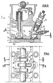
- Figures 1 to 4 show a part of a cylinder head 1 of an internal combustion engine with compression ignition according to the aforementioned patent of the Applicants.
- the engine block 2 delimits several cylinders such as 2a, the axes of which are contained in a longitudinal plane L.
- two intake valves 3 each cooperate with an intake duct 4 and an exhaust valve 5 cooperates with a exhaust duct 6.
- the axis a of the exhaust duct 6 is contained in the diametral plane D of the cylinder 2 perpendicular to the longitudinal plane L.
- the intake ducts 4 of the cylinder 2 are symmetrical to one another relative to the diametral plane D. As can be seen in FIGS.
- the exhaust duct 6 opens out on the same lateral face 7 as the two corresponding intake ducts 4 and the exhaust duct 6 opens out on this face 7 at an intermediate level between the level at which the intake ducts open and the plane 1a of the cylinder head gasket 1.
- the lateral face 8 of the cylinder head opposite the face 7 is perfectly clear, which allows the installation of a combustion pre-chamber 9 provided with an injector 10 and a glow plug 11.
- this arrangement allows for an extremely simple and compact distribution, from a single overhead camshaft 12 disposed at equal distance from the axes of the exhaust and intake valves which are all actuated by identical latches 13.
- FIG. 4 It can be seen in FIG. 4 that around the cylinder 2 are provided, in the vicinity of the lateral faces 7 and 8, four screw passage holes 15 arranged at the four vertices of a rectangle centered with respect to the section of the cylinder 2. It is perfectly visible in Figure 4, the arrangement shown does not increase the number of through holes for the cylinder head fixing screws around the cylinder 2, by providing such through holes 15 arranged with their axis along the plane of symmetry D. Such an arrangement is therefore not suitable for high pressure motors.
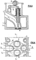
- the conduit 26 opens onto the lateral face 27, in a position offset laterally with respect to the diametral plane D and at an intermediate level between the level of the intake conduits 24 and the plane 21a of the cylinder head gasket 21.
- This position of the conduit exhaust 26 is very slightly to the right, that is to say towards the outside from a position directly above the intake duct 24 located on the right on face 27.
- This exhaust duct could alternatively be shifted to the left and located substantially in line with the intake duct 24 located on the left.
- the axis 26a of the intake duct 26 has, in projection on a plane parallel to the plane of the cylinder head gasket 21a, that is to say on a horizontal plane, the shape of a curve whose concavity is directed towards the diametral plane D.
- This axis 26a naturally presents, as in the case of the prior art, also a curvature in projection on a vertical plane such as the cutting plane of FIG. 2.
- the shape of the conduit 26 makes it possible to provide a hole 25a for the passage of a bolt for fixing the cylinder head 21 in the vicinity of the lateral face 27 and along the diametrical plane D.
- the passage hole 25a is disposed in the space located inside the concavity of the exhaust duct 26.
- Screw passage holes 25c and 25b are machined symmetrically with respect to the diametral plane D in the corresponding excess thickness of the wall of the cylinder head.
- four screw passage holes 25 are arranged at the four vertices of a rectangle surrounding the cylinder 22. There are therefore seven screw passage holes roughly regularly distributed around of the cylinder 22 for fixing the cylinder head at the level of this cylinder. This considerably increased number of roughly regularly distributed screws makes it possible to withstand very high pressures in the chamber of the cylinder 22.
- a screw 35 passes through the cylinder head through a passage opening 25'a situated along the diametrical plane D, in the vicinity of the face 28 and in a practically symmetrical position that of the passage hole 25a, with respect to the axis of the cylinder 22.
- the fixing with six screws per cylinder is completed by means of four passage holes 25 arranged along the vertices of a rectangle centered with respect to the cylinder 22.
- the position and the shape of the exhaust duct 26 are identical, this curved duct in horizontal and vertical projection opening onto the lateral face 27 in a position laterally offset from the diametrical plane D.
- the variants shown differ by the angular position of the passage hole 25'a of the screw 30, of the axis of the pre-chamber 29 and of the glow plug 31, relative to the plane D.
- the axis of the chamber 29 is defined as the trace of the plane of symmetry of the chamber and of the injector 30 on a plane parallel to the plane 21 a of the cylinder head gasket, such as the plane of FIGS. 8 to 12.
- a first variant ( Figures 8, 9 and 10) is characterized by an arrangement of the axis of the through hole 25'a in the diametral plane D, that is to say in a position which is substantially diametrically opposite with respect to at the position of the axis of the hole 25a.
- the axis of the through hole 25'a and the axis of the chamber 29 are contained in the diametral plane D, the axis of the glow plug 31 making an angle a with this plane.
- the axis of the chamber 29 and the glow plug 31 make an angle ⁇ with the diametrical plane D.
- the axis of the chamber 29 forms an angle 6 1 , less than the angle ⁇ of the sub-variant shown in FIG. 9 with the plane D, and the glow plug 31 forms an angle ⁇ 1 with the axis of the chamber 29, less than the angle a of the sub-variant shown in FIG. 8.
- a second variant shown in FIGS. 11 and 12 consists in placing the axis of the through hole 25'a outside the diametral plane D, in a position making an angle y with the plane D, seen from the axis of the cylinder 22 .
- the axis of the pre-chamber 29 and the axis of the glow plug 31 make the same angle (3 2 with the diametral plane D.
- the axis of the chamber 29 makes an angle 8 3 with the diametral plane D, this angle (3 3 being less than the angle ⁇ 2 of the sub-variant represented on the FIG. 11.
- the glow plug 31 is offset by an angle a2 relative to the axis of the pre-chamber 29.
- the arrangement according to the invention makes it possible to obtain improved tightening and fixing of the cylinder head by a notable increase in the number of screws. fixing around each cylinder, these fixing screws remaining approximately regularly distributed around the cylinder. This improvement is obtained thanks to a curved shape and a lateral offset of the exhaust duct.
Landscapes
- Engineering & Computer Science (AREA)
- Chemical & Material Sciences (AREA)
- Combustion & Propulsion (AREA)
- Mechanical Engineering (AREA)
- General Engineering & Computer Science (AREA)
- Cylinder Crankcases Of Internal Combustion Engines (AREA)
- Valve-Gear Or Valve Arrangements (AREA)
Claims (11)
Priority Applications (1)
| Application Number | Priority Date | Filing Date | Title |
|---|---|---|---|
| AT87401175T ATE48675T1 (de) | 1986-07-04 | 1987-05-25 | Zylinderkopf fuer eine brennkraftmaschine mit drei ventilen pro zylinder und mit hohem druck in den zylindern. |
Applications Claiming Priority (2)
| Application Number | Priority Date | Filing Date | Title |
|---|---|---|---|
| FR8609775A FR2601076B1 (fr) | 1986-07-04 | 1986-07-04 | Culasse de moteur a combustion interne a trois soupapes par cylindre et a forte pression dans les cylindres. |
| FR8609775 | 1986-07-04 |
Publications (2)
| Publication Number | Publication Date |
|---|---|
| EP0251835A1 EP0251835A1 (de) | 1988-01-07 |
| EP0251835B1 true EP0251835B1 (de) | 1989-12-13 |
Family
ID=9337104
Family Applications (1)
| Application Number | Title | Priority Date | Filing Date |
|---|---|---|---|
| EP87401175A Expired EP0251835B1 (de) | 1986-07-04 | 1987-05-25 | Zylinderkopf für eine Brennkraftmaschine mit drei Ventilen pro Zylinder und mit hohem Druck in den Zylindern |
Country Status (4)
| Country | Link |
|---|---|
| EP (1) | EP0251835B1 (de) |
| AT (1) | ATE48675T1 (de) |
| DE (1) | DE3761159D1 (de) |
| FR (1) | FR2601076B1 (de) |
Families Citing this family (2)
| Publication number | Priority date | Publication date | Assignee | Title |
|---|---|---|---|---|
| DE3819656C1 (de) * | 1988-06-09 | 1989-02-02 | Daimler-Benz Ag, 7000 Stuttgart, De | |
| JPH02140407A (ja) * | 1988-08-01 | 1990-05-30 | Honda Motor Co Ltd | 多気筒エンジンのシリンダヘッド構造 |
Family Cites Families (8)
| Publication number | Priority date | Publication date | Assignee | Title |
|---|---|---|---|---|
| US2380066A (en) * | 1941-03-25 | 1945-07-10 | Pescara Raul Pateras | Internal-combustion engine |
| GB766187A (en) * | 1953-11-26 | 1957-01-16 | Ricardo & Co Engineers | Improvements in detachable cylinder head constructions for liquid-cooled internal combustion engines |
| FR1264423A (fr) * | 1960-08-05 | 1961-06-19 | Maschf Augsburg Nuernberg Ag | Culasse de cylindre comportant trois soupapes d'admission ou davantage par cylindre,pour moteurs à combustion interne comportant un mouvement de rotation de l'air autour de l'axe longitudinal du cylindre |
| AT307165B (de) * | 1970-03-06 | 1973-05-10 | List Hans | Zylinderkopf einer Brennkraftmaschine mit zwei Einlaßventilen je Zylinder |
| FR2105641A5 (de) * | 1970-09-08 | 1972-04-28 | Berliet Automobiles | |
| FR2142618B1 (de) * | 1971-06-22 | 1973-05-25 | Peugeot | |
| US4369627A (en) * | 1978-11-07 | 1983-01-25 | Cummins Engine Company, Inc. | Internal combustion engine |
| FR2562162B1 (fr) * | 1984-03-27 | 1988-05-27 | Peugeot | Culasse pour moteur a combustion interne a trois soupapes |
-
1986
- 1986-07-04 FR FR8609775A patent/FR2601076B1/fr not_active Expired
-
1987
- 1987-05-25 DE DE8787401175T patent/DE3761159D1/de not_active Expired - Fee Related
- 1987-05-25 EP EP87401175A patent/EP0251835B1/de not_active Expired
- 1987-05-25 AT AT87401175T patent/ATE48675T1/de not_active IP Right Cessation
Also Published As
| Publication number | Publication date |
|---|---|
| FR2601076B1 (fr) | 1988-10-21 |
| FR2601076A1 (fr) | 1988-01-08 |
| EP0251835A1 (de) | 1988-01-07 |
| DE3761159D1 (de) | 1990-01-18 |
| ATE48675T1 (de) | 1989-12-15 |
Similar Documents
| Publication | Publication Date | Title |
|---|---|---|
| CA1067363A (en) | Internal combustion engine | |
| FR2607553A1 (fr) | Dispositif de support pour deux arbres a cames dans la culasse d'un moteur a plusieurs cylindres en ligne | |
| FR2581703A1 (fr) | Culasse refroidie par liquide | |
| FR2493919A1 (fr) | Moteur a combustion interne perfectionne | |
| EP0917558A4 (de) | Methode zur verminderung von ablagerungen in brennkammer und einlassventil einerfremdgezündeten brennkraftmaschine | |
| EP0768457A1 (de) | Fremdgezündete Viertaktbrennkraftmaschine mit direkter Kraftstoffeinspritzung | |
| EP0251835A1 (de) | Zylinderkopf für eine Brennkraftmaschine mit drei Ventilen pro Zylinder und mit hohem Druck in den Zylindern | |
| US5511520A (en) | Cylinder head construction | |
| EP0565410B1 (de) | Integrierte Rampenvorrichtung für die Abgasrückführung einer Brennkraftmaschine | |
| EP0293278B1 (de) | Multiventil-Zylinderkopf für Brennkraftmaschine | |
| EP0470874B1 (de) | Brennkraftmaschine mit Lufteinlasseinrichtung integriert in einem Zylinderkopf | |
| EP0159249B1 (de) | Zylinderkopf mit drei Ventilen für eine Brennkraftmaschine | |
| JPH0526099A (ja) | 水冷式内燃機関 | |
| EP0209426B1 (de) | Zylinderkopf einer Brennkraftmaschine mit drei Ventilen pro Zylinder | |
| FR2464374A1 (fr) | Moteur a combustion interne pourvu d'une enveloppe de refroidissement | |
| FR2719343A1 (fr) | Ensemble de bloc-moteur d'une seule pièce à quatre temps. | |
| FR2765629A1 (fr) | Moteur a injection directe et allumage commande | |
| JP3444022B2 (ja) | 吸気マニホルド一体型ロッカカバー付内燃機関 | |
| EP0187099A1 (de) | Zylinderkopf für eine Brennkraftmaschine | |
| FR2812030A1 (fr) | "moteur a combustion interne" | |
| CH642143A5 (en) | Intake/exhaust unit for a four-stroke internal combustion engine | |
| WO2000034640A1 (fr) | Culasse de moteur a combustion interne refroidie par liquide | |
| FR2655381A1 (fr) | Culasse pour moteur a combustion interne, et moteur muni de cette culasse. | |
| FR2458686A1 (fr) | Moteur a combustion interne, a pistons a mouvements alternatifs, de type en v | |
| FR2729713A1 (fr) | Culasse d'un moteur a combustion interne a piston alternatif |
Legal Events
| Date | Code | Title | Description |
|---|---|---|---|
| PUAI | Public reference made under article 153(3) epc to a published international application that has entered the european phase |
Free format text: ORIGINAL CODE: 0009012 |
|
| AK | Designated contracting states |
Kind code of ref document: A1 Designated state(s): AT DE GB IT |
|
| 17P | Request for examination filed |
Effective date: 19871207 |
|
| 17Q | First examination report despatched |
Effective date: 19881230 |
|
| GRAA | (expected) grant |
Free format text: ORIGINAL CODE: 0009210 |
|
| AK | Designated contracting states |
Kind code of ref document: B1 Designated state(s): AT DE GB IT |
|
| REF | Corresponds to: |
Ref document number: 48675 Country of ref document: AT Date of ref document: 19891215 Kind code of ref document: T |
|
| REF | Corresponds to: |
Ref document number: 3761159 Country of ref document: DE Date of ref document: 19900118 |
|
| ITF | It: translation for a ep patent filed | ||
| GBT | Gb: translation of ep patent filed (gb section 77(6)(a)/1977) | ||
| PLBE | No opposition filed within time limit |
Free format text: ORIGINAL CODE: 0009261 |
|
| STAA | Information on the status of an ep patent application or granted ep patent |
Free format text: STATUS: NO OPPOSITION FILED WITHIN TIME LIMIT |
|
| 26N | No opposition filed | ||
| ITTA | It: last paid annual fee | ||
| PGFP | Annual fee paid to national office [announced via postgrant information from national office to epo] |
Ref country code: AT Payment date: 20010419 Year of fee payment: 15 |
|
| PGFP | Annual fee paid to national office [announced via postgrant information from national office to epo] |
Ref country code: DE Payment date: 20010420 Year of fee payment: 15 |
|
| PGFP | Annual fee paid to national office [announced via postgrant information from national office to epo] |
Ref country code: GB Payment date: 20010518 Year of fee payment: 15 |
|
| REG | Reference to a national code |
Ref country code: GB Ref legal event code: IF02 |
|
| PG25 | Lapsed in a contracting state [announced via postgrant information from national office to epo] |
Ref country code: GB Free format text: LAPSE BECAUSE OF NON-PAYMENT OF DUE FEES Effective date: 20020525 Ref country code: AT Free format text: LAPSE BECAUSE OF NON-PAYMENT OF DUE FEES Effective date: 20020525 |
|
| PG25 | Lapsed in a contracting state [announced via postgrant information from national office to epo] |
Ref country code: DE Free format text: LAPSE BECAUSE OF NON-PAYMENT OF DUE FEES Effective date: 20021203 |
|
| GBPC | Gb: european patent ceased through non-payment of renewal fee |
Effective date: 20020525 |
|
| PG25 | Lapsed in a contracting state [announced via postgrant information from national office to epo] |
Ref country code: IT Free format text: LAPSE BECAUSE OF NON-PAYMENT OF DUE FEES;WARNING: LAPSES OF ITALIAN PATENTS WITH EFFECTIVE DATE BEFORE 2007 MAY HAVE OCCURRED AT ANY TIME BEFORE 2007. THE CORRECT EFFECTIVE DATE MAY BE DIFFERENT FROM THE ONE RECORDED. Effective date: 20050525 |