EP0187220A2 - Cheminée montée avec une porte à deux battants - Google Patents
Cheminée montée avec une porte à deux battants Download PDFInfo
- Publication number
- EP0187220A2 EP0187220A2 EP85114223A EP85114223A EP0187220A2 EP 0187220 A2 EP0187220 A2 EP 0187220A2 EP 85114223 A EP85114223 A EP 85114223A EP 85114223 A EP85114223 A EP 85114223A EP 0187220 A2 EP0187220 A2 EP 0187220A2
- Authority
- EP
- European Patent Office
- Prior art keywords
- door
- door leaf
- leaf
- tongue
- stove according
- Prior art date
- Legal status (The legal status is an assumption and is not a legal conclusion. Google has not performed a legal analysis and makes no representation as to the accuracy of the status listed.)
- Granted
Links
- 238000002485 combustion reaction Methods 0.000 claims abstract description 15
- 238000013459 approach Methods 0.000 abstract description 2
- 239000000446 fuel Substances 0.000 description 3
- 239000011521 glass Substances 0.000 description 1
- 230000003993 interaction Effects 0.000 description 1
- 239000002184 metal Substances 0.000 description 1
- 238000000926 separation method Methods 0.000 description 1
- 238000009423 ventilation Methods 0.000 description 1
Images

Classifications
-
- F—MECHANICAL ENGINEERING; LIGHTING; HEATING; WEAPONS; BLASTING
- F24—HEATING; RANGES; VENTILATING
- F24B—DOMESTIC STOVES OR RANGES FOR SOLID FUELS; IMPLEMENTS FOR USE IN CONNECTION WITH STOVES OR RANGES
- F24B1/00—Stoves or ranges
- F24B1/18—Stoves with open fires, e.g. fireplaces
- F24B1/191—Component parts; Accessories
- F24B1/192—Doors; Screens; Fuel guards
Definitions
- the invention relates to a stove with a combustion chamber and a double-leaf door arranged in front of the combustion chamber, the door leaves, one of which partially overlaps the other in the closed position, are each pivotably mounted by means of hinges attached to the stove, preferably about vertical axes.
- the invention has for its object to provide a stove with two-leaf door so on, that its two door wings close automatically i l1 the correct order and without mutual interference when they are released.
- each door leaf of the two-leaf door of the stove is assigned at least one spring pressing it into the closed position and that one acting on the overlapping door leaf to ent from the other door leaf locking lock is provided.
- At least one of the two hinges of each door leaf is provided with a return spring, ie the return springs are in the Chimney stove according to the invention integrated into the hinges of the door wing concerned and thus do not form any disturbing projecting components.
- At least one of the hinges of each door leaf can be provided with a 1 cm opening stop in order to limit the pivoting movements of the door leaf into the opening position. This not only prevents uncontrolled swiveling movements of the door leaves in the opening direction, but also creates an end position in which the lower door leaf can be held as long as you want to keep the door open in order to handle the fuel chamber or add fuel.
- the lock is a tongue which can be pivoted into the movement path of the overlapping door leaf and which is preferably biased into the locked position by means of a spring acting on it.
- the tongue is thus pressed into the locked position as soon as the overlapping door leaf has been moved over the tongue during its opening movement.
- the tongue is preferably provided with a notch into which an edge of the overlapping door leaf engages when the overlapping door leaf is pushed back in the direction of its closed position by the spring acting on it.
- the tongue is connected to a trigger which is actuated by the other, namely the engaging door leaf, when the latter approaches the closed position when it returns to the closed position.
- This trigger is preferably a lever which interacts with the lower edge of the engaging door and is connected to the tongue forming the lock via a shaft mounted below the combustion chamber or the separation chamber on the stove. Therefore, the spring acting on the tongue not only presses it into the locked position, but also the release lever upwards into the path of movement of the lower door leaf, so that the lower door leaf runs on this appropriately curved release lever when it returns to the closed position and follows it -presses down.
- the stove according to the invention can be installed anywhere, i.e. can also be connected to chimneys to which several fireplaces are connected.
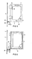
- a fireplace not shown in detail in the drawing, contains in its front wall 1 an opening 2 leading to a combustion chamber, which is to be closed by means of a double-leaf door 3.
- Each door leaf 4 and 5 each has an outer frame 6, which contains a glass pane 7 as a filling.
- a handle 8 is used to operate the relevant door leaf.
- the door leaf 4 shown on the left in the drawing contains 6 ventilation openings 9 in the frame which can be opened and closed by means of a manually operated slide 10.
- the door leaf 4 shown on the left in the drawing is provided on its outer edge with a tab 11 which, when the door is closed, lies behind the free edge of the other door leaf 5 in order to completely close the opening 2 in the furnace wall 1, as in particular FIG. 2 shows. Therefore, the door panels 4 and 5 must be such one after the other be closed that the left door leaf 4 comes in front of the right door leaf 5 in the closed position.
- Each door leaf 4 and 5 is pivotally mounted on the wall 1 of the stove by means of two identical hinges 12 ' .
- Each hinge has a hinge element 13 fastened to the relevant door leaf 4 or 5 and a hinge element 14 fastened to the wall 1, which are connected to one another via a hinge pin 15 inserted therein.
- a helical spring 16 is arranged on the hinge pin 15, one end 17 of which is attached to the hinge element 14 and the other end 18 of which is attached to the hinge element 13.
- the helical spring 16 is preloaded in such a way that it presses the movable hinge element 13 into the rest position, in which the relevant door leaf 4 or 5 lies in front of the opening 2 and the door 3 is accordingly closed.
- a stop 19 is fastened to the movable hinge element 13 of the upper hinge 12 of this door leaf 4 or 5, which abuts the foot 20 of the fixed hinge element 14 when the door leaf is fully open and thus limits the pivoting movement of the door leaf in question.
- a releasable lock 21 is provided below the door 3, which holds the right door leaf 5 in the position shown in FIG. 3 when pivoting back until the other, namely the left door leaf 4 is pivoted past it and the door leaves 4 and 5 therefore lay in the correct order one after the other in front of the opening 2 and close it properly.
- the lock 21 consists of a pivotally mounted tongue 22 which projects approximately at right angles from the wall 1 and a notch at the outer end 23, into which the rear ceiling 24 of the right door leaf 5 can snap, as shown in FIGS. 3 and 6.
- the tongue 22 consisting of a sheet metal blank is fastened on one end of an axis 25 which is rotatably mounted in two eyes 26 and 27 fastened on the outside of the wall 1.
- a leaf spring 28 which presses the tongue up into the locking position, as shown in FIG. 6.
- the tongue 22 In order to lead the tongue 22 out of the locked position and accordingly to release the door leaf 5 for complete pivoting, the tongue 22 must be pressed down against the biasing force of the leaf spring 28.
- a helical spring can also be provided.
- a curved release lever 29 is attached in a rotationally fixed manner to the opposite end of the axis 25, which is connected to the lower edge 30 of the left door leaf 4, i.e. of the door leaf, which must first be closed, interacts.
- the other door leaf 4 can swing back into the closed position unhindered when you let it go. Shortly before the closing position is reached, its lower edge 30 comes into contact with the curved lever 29 and presses it downward, since the zenith 32 of its curvature is higher than the plane of movement of the lower edge 30 of the door leaf 4 until it approximately reaches the position shown in FIG. 5 lower position shown in broken lines has reached. Since the lever 29 is rotatably connected to the axis 25, the axis 25 is accordingly rotated accordingly. Since the tongue 22 is also non-rotatably connected to the axis 25, the tongue 22 is also pivoted downward into the position shown in broken lines in FIG. 6, which is possible because the leaf spring 28 can deflect downward. Due to the pivoting movement, the tongue 22 is adjusted under the lower edge 31 of the door leaf 5 and accordingly releases the door leaf 5, so that it can now further swivel under the influence of the spring 16.
- the lock 21 is only released when it is ensured that the door leaves 4 and 5 close one after the other in the desired order . It is therefore avoided that the door leaf 5 can return to the closed position in front of the door leaf 4 or hinder the closing movement of the door leaf 4.
Landscapes
- Engineering & Computer Science (AREA)
- Chemical & Material Sciences (AREA)
- Combustion & Propulsion (AREA)
- Mechanical Engineering (AREA)
- General Engineering & Computer Science (AREA)
- Electric Stoves And Ranges (AREA)
- Special Wing (AREA)
- Glass Compositions (AREA)
- Closing And Opening Devices For Wings, And Checks For Wings (AREA)
- Buildings Adapted To Withstand Abnormal External Influences (AREA)
Priority Applications (1)
| Application Number | Priority Date | Filing Date | Title |
|---|---|---|---|
| AT85114223T ATE50049T1 (de) | 1985-01-10 | 1985-11-08 | Kaminofen mit zweifluegeliger tuer. |
Applications Claiming Priority (2)
| Application Number | Priority Date | Filing Date | Title |
|---|---|---|---|
| DE3500572 | 1985-01-10 | ||
| DE19853500572 DE3500572A1 (de) | 1985-01-10 | 1985-01-10 | Kaminofen mit zweifluegeliger tuer |
Publications (3)
| Publication Number | Publication Date |
|---|---|
| EP0187220A2 true EP0187220A2 (fr) | 1986-07-16 |
| EP0187220A3 EP0187220A3 (en) | 1988-04-20 |
| EP0187220B1 EP0187220B1 (fr) | 1990-01-31 |
Family
ID=6259529
Family Applications (1)
| Application Number | Title | Priority Date | Filing Date |
|---|---|---|---|
| EP85114223A Expired - Lifetime EP0187220B1 (fr) | 1985-01-10 | 1985-11-08 | Cheminée montée avec une porte à deux battants |
Country Status (4)
| Country | Link |
|---|---|
| EP (1) | EP0187220B1 (fr) |
| AT (1) | ATE50049T1 (fr) |
| DE (2) | DE3500572A1 (fr) |
| DK (1) | DK9786A (fr) |
Cited By (3)
| Publication number | Priority date | Publication date | Assignee | Title |
|---|---|---|---|---|
| EP1223384A1 (fr) * | 2001-01-12 | 2002-07-17 | Deckert Maschinenbau GmbH | Dispositif de fermeture pour porte de foyer |
| EP1437551A1 (fr) * | 2003-01-10 | 2004-07-14 | Olsberg Hermann Everken GmbH | Atre de combustible solide pour la domaine doméstique |
| IT201600092539A1 (it) * | 2016-09-14 | 2018-03-14 | La Nordica S P A | Meccanismo di apertura e chiusura della porta di una stufa |
Families Citing this family (1)
| Publication number | Priority date | Publication date | Assignee | Title |
|---|---|---|---|---|
| US6378592B1 (en) * | 1999-03-16 | 2002-04-30 | Stephen G. Kimmet | Security system for a cubicle |
Family Cites Families (3)
| Publication number | Priority date | Publication date | Assignee | Title |
|---|---|---|---|---|
| FR2359447A1 (fr) * | 1976-07-22 | 1978-02-17 | Grego Bruno | Perfectionnement a la commande automatique des portails a deux battants |
| GB2129037A (en) * | 1982-11-02 | 1984-05-10 | John Donald Catterall | Door assembly |
| DE8335576U1 (de) * | 1983-12-12 | 1985-05-15 | Dorma-Baubeschlag Gmbh & Co Kg, 5828 Ennepetal | Einrichtung zur uebertragung der schwenkbewegung eines standfluegels auf die oeffnungs-schwenkbewegung eines gangfluegels |
-
1985
- 1985-01-10 DE DE19853500572 patent/DE3500572A1/de not_active Withdrawn
- 1985-11-08 AT AT85114223T patent/ATE50049T1/de not_active IP Right Cessation
- 1985-11-08 DE DE8585114223T patent/DE3575778D1/de not_active Expired - Fee Related
- 1985-11-08 EP EP85114223A patent/EP0187220B1/fr not_active Expired - Lifetime
-
1986
- 1986-01-09 DK DK9786A patent/DK9786A/da not_active Application Discontinuation
Cited By (3)
| Publication number | Priority date | Publication date | Assignee | Title |
|---|---|---|---|---|
| EP1223384A1 (fr) * | 2001-01-12 | 2002-07-17 | Deckert Maschinenbau GmbH | Dispositif de fermeture pour porte de foyer |
| EP1437551A1 (fr) * | 2003-01-10 | 2004-07-14 | Olsberg Hermann Everken GmbH | Atre de combustible solide pour la domaine doméstique |
| IT201600092539A1 (it) * | 2016-09-14 | 2018-03-14 | La Nordica S P A | Meccanismo di apertura e chiusura della porta di una stufa |
Also Published As
| Publication number | Publication date |
|---|---|
| DE3500572A1 (de) | 1986-07-10 |
| DK9786D0 (da) | 1986-01-09 |
| ATE50049T1 (de) | 1990-02-15 |
| EP0187220A3 (en) | 1988-04-20 |
| EP0187220B1 (fr) | 1990-01-31 |
| DE3575778D1 (de) | 1990-03-08 |
| DK9786A (da) | 1986-07-11 |
Similar Documents
| Publication | Publication Date | Title |
|---|---|---|
| DE2444628C2 (de) | Panikverschluß | |
| DE3234677A1 (de) | Beschlag fuer einen zumindest parallelabstellbaren fluegel eines fensters, einer tuer od. dgl. | |
| EP2147178A1 (fr) | Agencement de charnière | |
| DE3142959C2 (de) | Treibstangenverschluß für Türen | |
| DE3320824C2 (fr) | ||
| EP2094924A2 (fr) | Serrure pour portes d'aéronefs, en particulier d'hélicoptères | |
| EP2085554B1 (fr) | Procédé de réglage de la suite d'ouverture de deux portes pivotantes à deux ventaux | |
| DE2747991C2 (de) | Schwenkhandhabenbetätigbares Schloß mit Drehfalle und Innen-Notöffnungseinrichtung für Kühlgeräte, Kühlräume oder dergleichen | |
| EP2673446A1 (fr) | Grille de protection | |
| EP0187220B1 (fr) | Cheminée montée avec une porte à deux battants | |
| DE29521068U1 (de) | Antrieb für eine Drehflügeltür in Flucht- und Rettungswegen | |
| DE19902579C2 (de) | Verschlußvorrichtung für den unterschlagenden Flügel zweiflügeliger setzholzloser Fenster oder Türen | |
| AT395631B (de) | Schliessfolgeregeleinrichtung fuer zweifluegelige tueren, insbesondere brandschutztueren | |
| EP0872616B1 (fr) | Porte à deux vantaux avec caractéristiques d'anti-paniques complètes | |
| DE3417054A1 (de) | Treibstangenverschluss fuer den standfluegel von zweifluegeligen tueren, insbesondere selbsttaetig schliessenden feuerschutztueren | |
| DE3719040A1 (de) | Spaltlueftungsvorrichtung fuer einen drehkipp-fluegel eines fensters, einer tuer od. dgl. | |
| EP1067270B1 (fr) | Dispositif de verrouillage pour un volet d'une ouverture de bâtiment, notamment pour un volet roulant | |
| DE2904987C2 (de) | Beschlag für Kipp-Schwenkflügel von Fenstern, Türen od. dgl. | |
| DE1623195U (de) | Tuerschloss fuer fahrzeuge, insbesondere kraftwagen. | |
| DE604514C (de) | Oberlichtoeffner | |
| EP0174441B1 (fr) | Dispositif de verrouillage pour un battant de porte pouvant être enclenché avant le déblocage de son système d'ouverture | |
| DE139763C (fr) | ||
| EP4520908A1 (fr) | Système de fermeture et porte à deux battants | |
| DE2554630C3 (de) | Beschlag für Drehkippfenster | |
| DE2443647A1 (de) | Waagrecht-schiebefenster oder -tuere |
Legal Events
| Date | Code | Title | Description |
|---|---|---|---|
| PUAI | Public reference made under article 153(3) epc to a published international application that has entered the european phase |
Free format text: ORIGINAL CODE: 0009012 |
|
| AK | Designated contracting states |
Kind code of ref document: A2 Designated state(s): AT BE CH DE FR GB IT LI LU NL SE |
|
| PUAL | Search report despatched |
Free format text: ORIGINAL CODE: 0009013 |
|
| AK | Designated contracting states |
Kind code of ref document: A3 Designated state(s): AT BE CH DE FR GB IT LI LU NL SE |
|
| 17P | Request for examination filed |
Effective date: 19881013 |
|
| 17Q | First examination report despatched |
Effective date: 19890411 |
|
| GRAA | (expected) grant |
Free format text: ORIGINAL CODE: 0009210 |
|
| AK | Designated contracting states |
Kind code of ref document: B1 Designated state(s): AT BE CH DE FR LI LU NL |
|
| REF | Corresponds to: |
Ref document number: 50049 Country of ref document: AT Date of ref document: 19900215 Kind code of ref document: T |
|
| REF | Corresponds to: |
Ref document number: 3575778 Country of ref document: DE Date of ref document: 19900308 |
|
| ET | Fr: translation filed | ||
| PG25 | Lapsed in a contracting state [announced via postgrant information from national office to epo] |
Ref country code: AT Effective date: 19901108 |
|
| PLBE | No opposition filed within time limit |
Free format text: ORIGINAL CODE: 0009261 |
|
| STAA | Information on the status of an ep patent application or granted ep patent |
Free format text: STATUS: NO OPPOSITION FILED WITHIN TIME LIMIT |
|
| PG25 | Lapsed in a contracting state [announced via postgrant information from national office to epo] |
Ref country code: LU Free format text: LAPSE BECAUSE OF NON-PAYMENT OF DUE FEES Effective date: 19901130 Ref country code: LI Effective date: 19901130 Ref country code: CH Effective date: 19901130 Ref country code: BE Effective date: 19901130 |
|
| 26N | No opposition filed | ||
| BERE | Be: lapsed |
Owner name: NOWO NOTTROTT & WOLF Effective date: 19901130 |
|
| PG25 | Lapsed in a contracting state [announced via postgrant information from national office to epo] |
Ref country code: NL Effective date: 19910601 |
|
| NLV4 | Nl: lapsed or anulled due to non-payment of the annual fee | ||
| PG25 | Lapsed in a contracting state [announced via postgrant information from national office to epo] |
Ref country code: FR Effective date: 19910731 |
|
| REG | Reference to a national code |
Ref country code: CH Ref legal event code: PL |
|
| PG25 | Lapsed in a contracting state [announced via postgrant information from national office to epo] |
Ref country code: DE Effective date: 19910801 |
|
| REG | Reference to a national code |
Ref country code: FR Ref legal event code: ST |