EP0187249A2 - Apparat zur Herstellung von Halbleiteranordnungen - Google Patents
Apparat zur Herstellung von Halbleiteranordnungen Download PDFInfo
- Publication number
- EP0187249A2 EP0187249A2 EP85115144A EP85115144A EP0187249A2 EP 0187249 A2 EP0187249 A2 EP 0187249A2 EP 85115144 A EP85115144 A EP 85115144A EP 85115144 A EP85115144 A EP 85115144A EP 0187249 A2 EP0187249 A2 EP 0187249A2
- Authority
- EP
- European Patent Office
- Prior art keywords
- chamber
- treated
- treatment
- heat
- side wall
- Prior art date
- Legal status (The legal status is an assumption and is not a legal conclusion. Google has not performed a legal analysis and makes no representation as to the accuracy of the status listed.)
- Granted
Links
Images


Classifications
-
- H—ELECTRICITY
- H10—SEMICONDUCTOR DEVICES; ELECTRIC SOLID-STATE DEVICES NOT OTHERWISE PROVIDED FOR
- H10P—GENERIC PROCESSES OR APPARATUS FOR THE MANUFACTURE OR TREATMENT OF DEVICES COVERED BY CLASS H10
- H10P95/00—Generic processes or apparatus for manufacture or treatments not covered by the other groups of this subclass
- H10P95/90—Thermal treatments, e.g. annealing or sintering
-
- B—PERFORMING OPERATIONS; TRANSPORTING
- B25—HAND TOOLS; PORTABLE POWER-DRIVEN TOOLS; MANIPULATORS
- B25J—MANIPULATORS; CHAMBERS PROVIDED WITH MANIPULATION DEVICES
- B25J9/00—Program-controlled manipulators
- B25J9/10—Program-controlled manipulators characterised by positioning means for manipulator elements
- B25J9/106—Program-controlled manipulators characterised by positioning means for manipulator elements with articulated links
- B25J9/1065—Program-controlled manipulators characterised by positioning means for manipulator elements with articulated links with parallelograms
- B25J9/107—Program-controlled manipulators characterised by positioning means for manipulator elements with articulated links with parallelograms of the froglegs type
-
- H—ELECTRICITY
- H10—SEMICONDUCTOR DEVICES; ELECTRIC SOLID-STATE DEVICES NOT OTHERWISE PROVIDED FOR
- H10P—GENERIC PROCESSES OR APPARATUS FOR THE MANUFACTURE OR TREATMENT OF DEVICES COVERED BY CLASS H10
- H10P50/00—Etching of wafers, substrates or parts of devices
- H10P50/20—Dry etching; Plasma etching; Reactive-ion etching
- H10P50/24—Dry etching; Plasma etching; Reactive-ion etching of semiconductor materials
- H10P50/242—Dry etching; Plasma etching; Reactive-ion etching of semiconductor materials of Group IV materials
-
- H—ELECTRICITY
- H10—SEMICONDUCTOR DEVICES; ELECTRIC SOLID-STATE DEVICES NOT OTHERWISE PROVIDED FOR
- H10P—GENERIC PROCESSES OR APPARATUS FOR THE MANUFACTURE OR TREATMENT OF DEVICES COVERED BY CLASS H10
- H10P50/00—Etching of wafers, substrates or parts of devices
- H10P50/20—Dry etching; Plasma etching; Reactive-ion etching
- H10P50/26—Dry etching; Plasma etching; Reactive-ion etching of conductive or resistive materials
- H10P50/264—Dry etching; Plasma etching; Reactive-ion etching of conductive or resistive materials by chemical means
- H10P50/266—Dry etching; Plasma etching; Reactive-ion etching of conductive or resistive materials by chemical means by vapour etching only
- H10P50/267—Dry etching; Plasma etching; Reactive-ion etching of conductive or resistive materials by chemical means by vapour etching only using plasmas
-
- H—ELECTRICITY
- H10—SEMICONDUCTOR DEVICES; ELECTRIC SOLID-STATE DEVICES NOT OTHERWISE PROVIDED FOR
- H10P—GENERIC PROCESSES OR APPARATUS FOR THE MANUFACTURE OR TREATMENT OF DEVICES COVERED BY CLASS H10
- H10P72/00—Handling or holding of wafers, substrates or devices during manufacture or treatment thereof
- H10P72/04—Apparatus for manufacture or treatment
- H10P72/0431—Apparatus for thermal treatment
- H10P72/0434—Apparatus for thermal treatment mainly by convection
-
- H—ELECTRICITY
- H10—SEMICONDUCTOR DEVICES; ELECTRIC SOLID-STATE DEVICES NOT OTHERWISE PROVIDED FOR
- H10P—GENERIC PROCESSES OR APPARATUS FOR THE MANUFACTURE OR TREATMENT OF DEVICES COVERED BY CLASS H10
- H10P72/00—Handling or holding of wafers, substrates or devices during manufacture or treatment thereof
- H10P72/04—Apparatus for manufacture or treatment
- H10P72/0451—Apparatus for manufacturing or treating in a plurality of work-stations
- H10P72/0452—Apparatus for manufacturing or treating in a plurality of work-stations characterised by the layout of the process chambers
- H10P72/0456—Apparatus for manufacturing or treating in a plurality of work-stations characterised by the layout of the process chambers in-line arrangement
-
- H—ELECTRICITY
- H10—SEMICONDUCTOR DEVICES; ELECTRIC SOLID-STATE DEVICES NOT OTHERWISE PROVIDED FOR
- H10P—GENERIC PROCESSES OR APPARATUS FOR THE MANUFACTURE OR TREATMENT OF DEVICES COVERED BY CLASS H10
- H10P72/00—Handling or holding of wafers, substrates or devices during manufacture or treatment thereof
- H10P72/30—Handling or holding of wafers, substrates or devices during manufacture or treatment thereof for conveying, e.g. between different workstations
- H10P72/33—Handling or holding of wafers, substrates or devices during manufacture or treatment thereof for conveying, e.g. between different workstations into and out of processing chamber
- H10P72/3302—Mechanical parts of transfer devices
-
- Y—GENERAL TAGGING OF NEW TECHNOLOGICAL DEVELOPMENTS; GENERAL TAGGING OF CROSS-SECTIONAL TECHNOLOGIES SPANNING OVER SEVERAL SECTIONS OF THE IPC; TECHNICAL SUBJECTS COVERED BY FORMER USPC CROSS-REFERENCE ART COLLECTIONS [XRACs] AND DIGESTS
- Y10—TECHNICAL SUBJECTS COVERED BY FORMER USPC
- Y10S—TECHNICAL SUBJECTS COVERED BY FORMER USPC CROSS-REFERENCE ART COLLECTIONS [XRACs] AND DIGESTS
- Y10S134/00—Cleaning and liquid contact with solids
- Y10S134/902—Semiconductor wafer
Definitions
- the present invention relates to an apparatus for producing semiconductor devices by, for example, etching, heating and rinsing materials to be treated such as semiconductor wafers.
- chloride gases such as SiC1 4 , CC1 4 , BC1 3 , C1 2 have been generally used. Etching proceeds by the chemical reactions of Al with these etching gases.
- an etching chamber In the case of a sheet type etching process in which wafers are processed or etched one at a time, an etching chamber must be always maintained in a vacuum state in order to prevent corrosion by chlorine produced by the chemical reactions of water in the atmospheric air with the etching gases.
- an etching unit is disposed independently of post-treatment units so that there arises the problem that a large space is required for the installation of the whole apparatus for producing semiconductor devices. Furthermore, there arises the problem that the etched wafers are corroded because it takes a long period of time to transfer the etched wafers from the etching unit to the post-treatment unit.
- a partition plate b formed with a plurality of holes is disposed in a case a so that the case a is divided into an upper chamber and a lower chamber.
- a cassette c holding a plurality of wafers d is placed upon the partition plate b and the case a is air-tightly closed with a cover e.
- the wafers d are dried by the hot air discharged from dryers f disposed on the top of the case a and the hot air flows through the holes of the partition plate b and then is discharged through a discharge port g formed at a lower portion of one side wall of the case a into the surrounding atmosphere.
- the device of the type described above is of the batch type because the cassette c holding a plurality of wafers d is charged into the device. There arises the problem that such batch type heat-treatment device cannot be directly connected to an etching device.
- the chloride gases are used. That is, a semiconductor wafer is charged into a reaction vessel and then the reaction vessel is evacuated so that the glow discharge is produced in the reaction gas atmosphere. Then the reaction between a material to be etched on the wafer and the etching gases proceeds so that the material to be etched is changed into a volatile chemical compound. In this manner, the etching process proceeds..
- the etched wafer When the etching process is completed and the etched wafer is discharged from the reaction vessel into the surrounding atmosphere, the etched wafer still includes the etching gases. As a result, the chemical reactions proceed between these remaining etching gases and the water in the surrounding air so that a conductor pattern of the material not etched and remained on the wafer is attached. As a consequence, the conductor paths are broken and short-circuited.
- a heat-treatment device which can be directly connected tgo an etching device.
- a wafer etched in the etching device is immediately transferred by a conveyor or the like from the etching device into the heat-treatment chamber in which the transferred wafer is immediately subjected to the heat-treatment process by means of a normally heated heating plate and an air-heating device.
- a drive means for driving such conveyor or the like from the exterior of the heat-treatment chamber is needed.
- a power transmission means must interconnect between the exterior driving means and the conveyor or the like in the heat-treatment chamber through a hole formed through one side wall thereof.
- the hot gases are discharged out of the heat-treatment chamber through this hole into the surrounding atmosphere so that the operations of various devices disposed adjacent to the heat-treatment chamber are adversely affected by the temperature rise.
- the discharged gases contain the reaction or etching gases.
- the complex driving means for driving the conveyor or the like may be placed within the heat-treatment chamber.
- the driving means is exposed to high temperatures and the reaction gases within the heat-treatment chamber causes corrosion of the driving means.
- the driving means must be minimized as much as possible and the conveyor system or the like must be simplified as much as possible. Therefore, a belt conveyor is employed. Since a wafer is transported by the belt conveyor, it cannot be made into direct contact with a heating plate. As a result, there arise the problems that the wafer heating efficiency is considerably low, and that the positive and fast heat-treatment cannot be accomplished.
- RIE device Reactive Ion Etching device
- a pair of parallel electrodes are disposed within a vacuum vessel into which is introduced an etching gas, and a wafer is securely held in position on one of the electrodes.
- RF power is applied to one of the electrodes so that the plasma is produced, whereby the wafer is etched.
- the vacuum vessel is made of stainless steel and a chloride etching gas is introduced into the vacuum chamber, iron, nickel and chromium are discharged out of the vacuum vessel so that the wafer is contaminated and the properties or characteristics of the wafer are considerably degraded.
- the vacuum vessel is made of alumina or the inner aluminum surfaces of the vacuum vessel are oxidized.
- alumina is very expensive and has low strength, it is not preferable to use it to fabricate a vacuum chamber.
- the commpounds resulting from the etching process tend to attach the inner surfaces of the vacuum chamber so that in order to prevent the adverse effects of such compounds on the wafer, the interior of the vacuum chamber must be frequently cleaned.
- cleaning and maintenance are difficult.
- a first object of the present invention is to provide an apparatus for produoing semiconductor devices in which the post-treatments of materials to be treated can be immediately effected and which has a high degree of space efficiency.
- a second object of the present invention is to provide an apparatus for producing semiconductor devices in which the quantity of dust attached to a material to be treated in each treatment chamber can be easily and positively detected.
- a third object of the present invention is to provide an apparatus for producing semiconductor devices provided with a heat-treatment chamber which can uniformly heat a material to be treated within a short period of time; which is provided with a transport means; and which can be connected to an etching device so that materials to be treated can be automatically and continuously treated.
- a fourth object of the present invention is to provide an apparatus for producing semiconductor devices provided with a heat-treatment device capable of uniform heat-treatment at an extremely high rate.
- a fifth object of the present invention is to provide an apparatus for producing semiconductor devices provided with a plasma etching device whose maintenance is very easy and which is inexpensive.
- an apparatus for producing semiconductor devices comprising: a dry etching unit for dry etching a material to be treated, said dry etching unit having an etch chamber in which said material to be treated is etched, an electrode for applying RF power to said material to be treated which is securely held in position and a gas introduction means for introducing etching gases into said etch chamberm; a post-treatment unit in which the material etched in said dry etching unit effects post-treatment; and a transport means for transferring said material to be treated from said dry etching unit to said post-treatment unit, said transport means connected to said dry etching unit and said post-treatment -unit-
- an apparatus for producing semiconductor devices comprising: a plurality of treatment chambers for continuously and sequentially effecting various treatments on a material to be treated; and a conveyor means for transporting said material to be treated through said plurality of treatment chambers in one direction or in the opposite direction, whereby said
- an apparatus for producing semiconductor devices comprising: a dry etching unit for dry etching a material to be treated; and a heat-treatment unit communicated with said dry etching unit, said heat-treatment unit having a case whose opposed side walls are formed with an inlet for said material to be treated and an outlet for said treated material, a transporting means for transporting said material to be treated from said inlet' to said outlet of said case, and a heating means for heating said material which is transported by said transporting means.
- an apparatus for producing semiconductor devices comprising: an etching unit for dry etching a material to be treated; and a heat-treatment unit directly conncted to said dry etching unit, said heat-treatment unit having a case whose opposite side walls are formed with an inlet for said material to be treated and an outlet for said treated material, respectively, a transportation means for transporting said material ..to be treated from said inlet to said outlet of said case, and a contact heating means which is disposed adjacent to said transportation means and which, in the case of heating, is raised to be made into contact with said material being transported by said transportation means to heat said material.
- an apparatus for producing semiconductor devices comprising a dry etching unit for dry etching a material to be treated, said dry etching unit including an etch chamber in which said material to be treated is etched, an electrode disposed within said etching chamber for applying an RF power to said material to be treated which is securely held in position, a gas introduction means for introducing etching gases into said etch chamber, and detachable lining means for lining the inside surfaces of said etch chamber.
- a first embodiment of an apparatus for producing semiconductor devices comprises a load chamber 1, an etch chamber 2, an unload chamber 3, a buffer chamber 4, and a heat-treatment, or post-treatment chamber 5 which are arranged sequentially in the order named.
- An electrode 6 is disposed at a lower portion in the etch chamber 2 and pusher pins 7 which are disposed below the electrode 6 can vertically move through the electrode 6.
- Feeders 8 and 9 are disposed in the load and unload chambers 1 and 3, respectively, and each feeder 8 or 9 comprises two pairs of arms interconnected in the form of a pantagfaph and a supporting plate at the top of the feeder 8 or 9. When the arms are rotated, a material to be treated; that is, a semiconductor wafer is linearly transported.
- a belt conveyor 11 with pusher pins 10 is disposed within the buffer chamber 4 and a belt conveyor 12 is disposed within the heat-treatment chamber 5.
- a vertically movable hot plate 13 is disposed below the conveyor belt 12 in such a way that when the hot plate 13 is lifted to its uppermost position, the top surface of the hot plate 13 is higher than the top surface of the belt conveyor 12.
- a dryer 15 having two nozzles 14a and 14b is disposed above the conveyor belt 12. Heating elements 16 and 17 are disposed within the hot plate 13 and the dryer 15, respectively.
- a gate valve 18a is disposed between the load chamber 1 and its exterior; a gate valve 18b is interposed between the load chamber 1 and the etch chamber 2; a gate valve 18c is interposed between the etch chamber 2 and the unload chamber 3; and a gate valve 18d is interposed between the unload chamber 3 and the buffer chamber 4.
- a gas introduction pipe 30 is connected to the etch chamber 2. The gas introduction pipe 30 introduces etching gases into the etch chamber 2.
- the etch chamber 2 is communicated with an exhaust pipe 20 with a valve 19b while the load and unload chambers 1 and 3 are communicated with an exhaust pipe 21 with valves 19a and 19c.
- the exhaust pipes 20 and 21 are communicated with vacuum pumps (not shown).
- a conveyor belt 28 and an unload cassette 29 are disposed at the downstream side of the water-rinse chuck 22.
- the load cassette 24 is lowered so that a material to be treated, or wafer A is placed upon the conveyor belt 25 so that the wafer A is transported at a position above the setter 26. Thereafter the wafer A is positioned at one end of the setter 26 and when the setter 26 is li'fted, the wafer A is also lifted. At the same.time, the gate valve 18a is opened and the feeder 8 is driven in such a way that the supporting plate thereof is located below the wafer A. Next the setter 26 is lowered so that the wafer A is placed on the supporting plate of the feeder 8 and moved into the load chamber 1.
- the gate valve 18 is closed and the load chamber 1 is evacuated through the exhaust pipe 21 and then the gate valve 18b of the etch chamber 2 is opened so that the wafer A is moved into the etch chamber 2. Thereafter the pusher pins 7 are lifted so that the wafer A is lifted above the supporting plate of the feeder 8. Next the feeder 8 returns to the load chamber 1 while the pusher pins 7 are lowered so that the wafer A is placed upon the electrode 6. Under these conditions, the wafer A is etched and after etching the pusher pins 7 are lifted so that the wafer A is also lifted. Then the gate valve 18c of the unload chamber 3 is opened and the supporting plate of the feeder 9 is located below the wafer A.
- the wafer A is placed on the supporting plate of the feeder 9 and is moved into the unload chamber 3. Thereafter the gate valve 18c is closed while the gate valve 18d of the buffer chamber 4 is opened and the pusher pins 10 are moved upward so that the wafer A is lifted. After the feeder 9 has returned to the unload chamber 3, the pusher pins 10 are lowered so that the wafer A is placed on the conveyor belt 11. As the conveyor belt 11 is driven, the wafer A is moved into the heat-treatment chamber 5 and when the wafer A is located below the nozzzle l4, the hot plate 13, which is heated by the heating element 16, is raised above the belt conveyor 12 so that the wafer A is transferred onto the top surface of the hot plate 13.
- the air which is heated by the heating element 17 is discharged through the nozzles 14a and 14b against the wafer A so as to dry the same.
- the hot plate 13 is lowered and the conveyor belt 12 conveys the wafer A from the heat-treatment chamber to a position immediately above the water-rinse chuck 22.
- the water-rinse chuck 22 is moved upward and attached to the rear surface of the wafer A. While the wafer A is rotated, pure water is discharged against the wafer A through a water-rinse nozzle (not shown) so that the wafer A is uniformly water rinsed.
- the air is discharged through the same nozzle against the wafer A which is rotated at a high speed so that the wafer A is dried.
- the chuck 22 is lowered and the vacuum suction is released so that the wafer A is placed on the belt conveyor 23 and then transported by the conveyor 28 to the unload cassette 29.
- the post-treatment of the wafer can be immediately accomplished after the etching process so that corrosion of the wafer A can be effectively prevented.
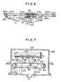
- a second embodiment of the present invention is shown in FIG. 2 while the chambers are connected linearly in the first embodiment, they are connected in the form of a U in the second embodiment so that the apparatus for producing semiconductor' devices can be made compact in size and therefore the installation space can be minimized. That is, according to the second embodiment, a load chamber 101, an etch chamber 102, an unload chamber 103, a buffer chamber (transfer station or stage) 104 and a heat treatment chamber 105 are connected in the form of a U.
- the etch chamber 102 is connected to the load chamber 101 and the unload chamber 103 through gate valves 118b and 118c, respectively.
- One surface of the entrance and another surface of the exit of the heat treatment chamber 105 are adjacent to each other.
- the transfer stage 104 is communicated through an air valve 118d with the unload chamber 103 and is directly communicated with the heat-treatment chamber 105.
- a water-rinse chuck 112 and a belt conveyor 123 are disposed at the downstream sidle of the heat treatment chamber 105 and a belt conveyor 128, an unload cassette 129 and an elevator 130 are disposed at the downstream side of the belt conveyor 123.
- a load cassette 124, an elevator 131, a belt conveyor 125, a setter 126 and a belt coneyor 127 are disposed at the upstream side of the load chamber 101.
- the load chamber 101 is communicated through an air valve 118a with the setter 127.
- a gas introduction pipe (not shown) which introduces etch gases into the etch chamber 102 is connected to the etch chamber 102.
- An electrode 106 is disposed in the etch chamber 102 and pusher pins 107 are disposed below the electrode 106 in such a way that they are movable through the electrode 106.
- Feeders 108 and 109 are disposed in the load chamber 101 and the unload chamber 103.
- Each of the feeders comprises two pairs of arms 108a (109a) interconnected in the form of a pantagraph and a supporting plate 108b (109b) at the leading end of the feeder. When the arms are rotated, a wafer is transported linearly.
- a belt conveyor 111 with pusher pins (not shown) is disposed within the transfer stage 104 and an L-shaped belt conveyor 112 is disposed in the heat treatment chamber 105.
- a vertically movable hot plate 113 is disposed below the belt conveyor 112 in such a way that when the hot plate 113 is lifted to its uppermost position, the top surface of the hot plate 113 is higher than the top surface of the belt conveyor 112.
- the wafers in the load cassette 124 are moved one at a time by the conveyor belt 125 to the feeder assembly 108 within the load chamber 101.
- the load chamber gate valve 118a is then closed and the load chamber 101 is evacuated.
- the gate valve 118b between the etch and load chambers is opened and the wafer is placed on the etching cathode 106.
- the gate valve '118b is closed, reactive gases .are introduced, the RF power supply is activated and etching is started.
- the etch chamber gate valves 118c are opend, the wafer is removed from the etch chamber 102 and transferred to the unload chamber 103. A new wafer is then loaded into the etch chamber 102.
- the etched wafer is moved onto the transfer stage 104 and then into the passivation chamber 105 for treatment. After passivation, the etched wafer is transferred onto the water rinse/spin dry station for final passivation treatment. Finally the etched wafer is then transferred into the unload cassette 129 by the conveyor belt 128.
- the post treatment chambers are sequentitally connected at the downstream side of the etch chamber so that the post treatments of the etched wafer can be accomplished immediately after the etching cycle.
- corrosion due to the reaction of the etched wafer with the surrounding atmosphere can be prevented.
- the post treatments include the heat treatment and the water rinse/spin drying cleaning treatment, but it is to be understood that only the heat-treatment or the water rinse/spin drying cleaning treatment may be employed and that any other required post-treatments may succeed to the etching process.
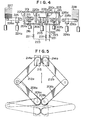
- a third embodiment of the present 'invention is shown in FIG. 4 and has a first treatment chamber 201, a second treatment chamber 202 and a third treatment chamber 103 connected with each other in the order named.
- An electrode 204 is disposed at a lower portion of the second treatment chamber 202 and pusher pins 206 which are moved vertically by means of an air cylinder 205 is disposed below the electrode 204.
- Feeders 207a and 207b are disposed in the first and third treatment chambers 201 and 203, respectively.
- the feeder 207 includes two first arms 208a and 208b and the upper ends of driving shafts 209a and 209b are securely joined to the lower surfaces at one ends of the first arms 208a and 208b, respectively.
- These driving shafts 209a and 209b carry gears 210a and 210b, respectively.
- the first arms 208a and 208b are so disposed symmetrically that the gears 210a and 210b engage with each other.
- the driving shafts 209a and 209b are rotatably supported by a supporting base 211.
- the first arms 208a and 208b are symmetrically rotated. about the axes of the driving shafts 209a and 209b, respectively.
- Second arms 212a and 212b which are equal in length to the first arms 208a and 208b, are connected through rotary shafts 213a and 213b to the other ends of the first arms 208a and 208b, respectively, so that the second arms 212a and 212b are rotated about the rotary shafts 213a and 213b, respectively, in parallel with the first arms 208a and 208b.
- Gears 214a and 214b are carried by the other ends of the second arms 212a and 212b, respectively, and the other ends of the second arms 212a and 212b are rotatably fixed to a wafer supporting plate 215 in such a way that the gears 214a and 214b are in mesh with each other.
- one of the first arms 208a (the left arm in FIGS. 5 and 6) is extended through the supporting base 211 and connected to a rotary drive means such as an electric motor 216.
- a stationary wheel 217 is disposed on the supporting base 211 in coaxial relationship with the driving shaft 209a connected to the motor 216.
- a rotating wheel 218 whose diameter is one half of that of the stationary wheel 217, is carried at the lower end of the rotary shaft 213a of the second arm 212a connected to the first arm 208a.
- a belt 219 is wrapped around the stationary wheel 217 and a rotating wheel 218 so that the rotation of the first arm 208a is transmitted to the second arm 212a.
- the motor 216 when the motor 216 is energized so that the driving shaft 209a is rotated, the other driving shaft 209b is caused to rotate in the opposite direction because of the engagement of the gears 210a and 210b so that the first arms 208a and 208b are caused to rotate symmetrically.
- the rotating wheel 218 Upon rotation of the first arm 208a, the rotating wheel 218 is rotated so that the second arm 212a is rotated in the direction opposite to the direction in which the first arm 208a rotates and concurrently the second arm 212b is also rotated because of the engagement between the gears 214a and 214b.
- a wafer placed on the supporting plate 215 is transported linearly.
- the first treatment chamber 201 is communicated with the surrounding atmosphere through a gate valve 220a and with the second treatment chamber 202 through a gate valve 220b.
- the second treatment chamber 202 is communicated through a gate valve 220c with the third treatment chamber 203 which in turn is communicated with the surrounding atmosphere through a gate valve 220d.
- the first and third treatment chambers 201 and 203 are communicated through valves 221 to an exhaust pipe 223 which in turn is communicated with a vacuum pump (not shown).
- the second treatment chamber 202 is communicated through a valve 221 to an exhaust valve 222 which in turn is communicated with a vacuum pump (not shown).
- Belt conveyors 226a and 226b are disposed adjacent to the gate valves 220a and 220d, respectively, of the first and third treatment chambers 201 and 203 and have pusher pins 225a and 225b, respectively, which are moved upward or downward by means of air cylinders 224a and 224b.
- a load cassette 227 is disposed at the upstream end of the belt conveyor 226a while an unload cassette 228 is disposed at the downstream end of the belt conveyor 226b.
- the load cassette 227 is lowered so that a wafer A is placed over the belt conveyor 226a which in turn moves the wafer A at a position immediately above the pusher pins 225a.
- the belt conveyor 226a is stopped and the pusher pins 225a are lifted so that the wafer A is also raised.
- the gate valve 220a is opened and the feeder 207a is energized in such a way that the supporting plate 215 is located immediately below the wafer A.
- the pusher pins 225a are lowered so that the wafer A is placed on the supporting plate 215 and is transferred into the first treatment chamber 201.
- the gate valve 220b between the first and second treatment chambers 201 and 202 is opened so that the wafer A is transferred into the second treatment chamber 202.
- the pusher pins 206 are raised so that the wafer A is raised to a position above the supporting plate 215.
- the pusher pins 206 are lowered so that the wafer A is placed upon the electrode 204. Under these conditions the wafer A is etched and upon completion of the etching cycle, the pusher pins 206 are again raised so that the wafer A is also raised.
- the gate valve 220c between the second and third treatment chambers 202 and 203 is opened and the supporting plate 215 of the feeder 207b is brought to a position immediately below the wafer A. Thereafter the pusher pins 206 are lowered so that the wafer A is transferred onto the supporting plate 215 of the feeder 207b. After the wafer A has been placed into the third treatment chamber 203, it is transferred onto the unload cassette 228 in reverse sequence to the transfer sequence described above.
- the feeders 207a and 207b and the belt conveyors 226a and 226b are so designed and constructed that the wafers are transported in the opposite directions. Therefore, for instance, the wafer A which has once been placed into the first treatment chamber 201 can be returned to the load cassette 227.
- the quantity of dust which has adhered to the wafer in the first treatment chamber 201 can be measured by comparing the quantity of dust adhered to the wafer before the latter is charged into the first treatment chamber 201 with the quantity of dust adhered to the wafer after the latter is discharged out of the first treatment chamber 201.
- the quantity of dust adhered to a wafer can be measured with the aid of a microscope.
- the wafer which has been placed into the second treatment chamber 202 can be returned to the load cassette 227 by means of the feeder 227a and the belt conveyor 226a.
- the quantity of dust adhered to the wafer in the second treatment chamber can be measured by subtracting from the quantity of dust adhered to the wafer returned to the load cassette 227 the quantity of dust adhered to the wafer before the latter was placed into the first treatment chamber 201 and the quantity of dust adhered to the wafer in the first chamber 201.
- the quantity of dust adhered to the wafer in the third treatment chamber 203 can be measured.
- the quantity of dust adhered to the wafer in each treatment chamber can be measured in a manner substantially similar to that described above..
- a wafer or a material to be treated which has been transferred into any desired treatment chamber can be returned to the entrance of the apparatus. Therefore, the quantity of dust adhered to a wafer in a specific treatment chamber can be easily and correctly measured by comparing the quantity of dust originally adhered to the wafer before it was charged into the apparatus with the quantity of dust adhered to the wafer discharged from said specific treatment chamber of the apparatus. Therefore, the quantity of dust or contaminants produced in each treatment chamber can be measured so that suitable countermeasures can be taken to avoid contamination of a wafer in each treatment chamber. As a result, a high yield can be ensured and the production efficiency can be improved.
- FIGS. 7 - 9 A fourth embodiment of the present invention is shown in FIGS. 7 - 9.
- One example of the etching processes utilizing chloride gases is shown in FIG. 9.
- Wafers from a wafer cassette 301 are charged one by one at a time into a load lock chamber 303 which is alternately maintained at an atmospheric pressure and a vacuum pressure.
- the load lock chamber 303 is evacuated, the wafers are transferred into a vacuum etch chamber 304 for treatment.
- they Upon completion of an etching cycle, they are transferred into a load lock chamber 305 and when the load lock chamber 305 is maintained at an atmospheric pressure, the wafers are transferred into an N 2 -gas chamber .306 so as to prevent the oxidation of the wafers.
- the N 2 -gas chamber 306 is provided in order to avoid the corrosion of the wafers due to the reaction with water in the air.
- the device or chamber 307 for effecting the heat-treatment of wafers is the last stage so that' it succeeds to the Nz-gas chamber 306.
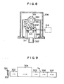
- a box-shaped case 308 has a wafer charging inlet 309 formed through the left wall and a wafer discharge outlet 310 formed through the right wall, the height of the wafer charging inlet 309 being euqal to that of the wafer discharge outlet 310.
- a pair of belt wheels 312 are supported by a frame 311 in the case 308 and a pair of endless belts circular in cross section are wrapped around the belt wheels 312 and spaced apart from each other by a suitable distance in the widthwise direction.
- the height of the endless belts 313 is equal to the height of the lower sides of the wafer charging inlet 309 and the wafer discharge outlet 310 so that a wafer 302 charged through the wafer charging inlet 309 is transferred onto the endless belts 313 and is transported toward the wafer discharge outlet 310.
- the endless belts 313 are driven by a motor 314 (See FIG. 8) through a suitable power transmission mechanism (not shown).
- a heating plate 316 is supported by insulation members 315 which in turn are erected from the frame 311.
- the heating plate 316 is located adjacent to the undersurface of the upper run of the endless belt 313 and the top surface of the heating plate 316 is formed with a pair of grooves 317 whose width is greater than the diameter of the endless belts 313 so that the upper surface of the heating plate 316 is maintained as close as possible to the wafer 302 on the endless belts 313 or is maintained in contact with the wafer 302.
- the heating plate 316 heats the undersurface of the wafer 302.
- Heating means or hot air,blowing cylinder 319 is supported by a frame 318 in opposed relationship with the top surfaces of the endless belts 313 and a heating element 320 such as a coil of nicrome wire is disposed within the cylinder 319.
- the hot air blowing cylinder 319 has blow-off openings 321 extended downward and spaced apart from the upper surface of the wafer 302 by a suitable distance. Therefore the air heated in the cylinder 319 is discharged through the blow-off openings 321 against the upper surface of the wafer 302.
- An air discharge port 322 is extended downwardly from the bottom of the box-shaped case 308 and is communicated with the surrounding air.
- the wafer 302 which has been etched in the etch chamber 304 is transferred into the load lock chamber 305 and then into the N 2 -gas chamber 306.
- the wafer 302 in the chamber 306 is inserted through the charging inlet 309 into the box-shaped case 308 and placed upon the endless belts 313.
- the wafer 302 Upon rotation of the motor 314, the wafer 302 is transported by the endless belts 313 toward the discharge outlet 310. During this time, the heating plate 316 heats the undersurface of the wafer 302 while the hot air is discharged from the hot-air-blow-off cylinder 319 against the upper surface of the wafer 302, whereby the compounds resulting from the reactions between the wafer 302 and the chloride gases in the N 2 -gas chamber 306 are removed. The hot air is discharged through the discharge port 322.
- the endless belts 313 are driven again so that the succeeding wafers are sequentially brought to the heat-treatment position.
- the heat-treatment of wafers can be continuously carried out.
- endless belts 313 have been described as having a circular cross sectional configuration, but it is to be understood that the present invention is not limited thereto and that the endless belts have a polygonal cross sectional configuration. Furthermore, instead of a pair of endless belts, a single wide and flat endless belt having a plurality of holes spaced, apart from each other along the center line of the belt may be used.
- the heating plate is maintained in contact with or almost in contact with the undersurface of the wafer while the hot air is discharged against the upper surface of the wafer so that the heat-treatment of the wafer can be accomplished uniformly in a short period of time.
- the problem of nonuniform temperature distribution in the prior art can be overcome.
- the heat-treatment chamber can be connected in series to the etch chamber so that the wafers can be transported one by one at a time sequentially throughout the treatment chambers so that, as compared with the prior art lot or batch processing systems, the treatment efficiency can be remarkably improved.
- the wafers have been described as being heated by the hot air discharged from the hot-air-blow-off cylinder and the heat plate, but it is to be understood that the wafers can be heated only by the hot air or by the heating plate.
- FIG. 10 shows a heat-treatment device incorporated in a fifth embodiment of an apparatus for producing semiconductor devices according to the present invention.
- An air-heating device 402 which is disposed at an upper portion of a closed treatment chamber 401 has hot-air discharge openings extended from the bottom of the air-heating device 402 and opened downwardly. The hot air heated in the air-heating device 402 is discharged downwardly through the hot air discharge openings 403.
- a heating plate 404 which is disposed immediately below the hot air discharge openings 4'03 is vertically movable by means of an air cylinder 405 or driving means disposed outside of the closed heat-treatment chamber 401. It is to be understood that instead of the air cylinder 405 any other suitable driving means such as a crank mechanism can be used.
- the upper surface of the heating plate 404 is formed with two grooves 480 extended in the longitudinal direction thereof and the upper runs of at least a pair of endless belts 407 (which is a wafer transport means) which are wrapped around belt wheels 406 disposed at both ends of the heating plate 404, are fitted into these grooves 408.
- the depth of the grooves 408 is so selected that the upper surface (upon which are placed wafers) of the heating plate 404 can be raised above the upper surfaces of the endless belts 307 and lowered below the upper surfaces of the endless belts 307.
- shutters 411 and 412 Disposed in opposed relationship with both ends of the heating plate 404 are shutters 411 and 412 which are adapted to open or close a wafer inlet 409 and a wafer outlet 410, respectively.
- the shutters 411 and 412 are made of a fluoro plastic and are securely attached to arms 415 and 416, respectively, which in turn are connected to the lower ends of heat-insulating members 413 and 414, respectively, depending from the lower surface of the heat plate 404. Therefore, when the heat plate 404 is raised, the shutters 411 and 412 close the wafer inlet and outlets 409 and 410, but when the heat plate 404 is lowered, the shutters 411 and 412 open the wafer inlet and outlet 409 and 410.
- a power transmission shaft 417 extended upwardly from the air cylinder 405 through the bottom of the heating chamber 401 is securely joined to the lower end of a heat-insulating member 418 depending from the lower surface of the heating plate 404.
- a ring member 419 made of a material such as fluoro, plastic which will not chemically react with etching gases produced in the closed heat-treatment chamber 401, is fitted over the shaft 417 and made into contact with the bottom of the heat-treatment chamber 401 and is securely held in position by means of a retainer 420 in such a way that any gap between the shaft 417 and the bottom of the heat-treatment chamber 401 is eliminated and the free vertical movement of the shaft 417 is permitted.
- the heating plate 404 In order to charge a wafer 421 into the heat-treatment chamber 401, the heating plate 404 is lowered so that the shutters 411 and 412 are also lowered, opening the wafer inlet and outlet 409 and 410. As the heating plate 404 is lowered, the upper-run surfaces of the endless belts 407 are raised above the upper surface of the heating plate 404 and the wafer 241 is transferred onto the endless belts 307. When the wafer 241 is transported through the heat-treatment chamber 401 and reaches a predetermined position, it is stopped by means of stoppers (not shown) so that it is located immediately below the hot air discharge opening 403.
- the heating plate 404 is raised above the upper-run surfaces of the endless belts 407 so that the wafer 421 is transferred onto the heating plate 404 and is made into intimate contact with the upper surface thereof.
- the shutters 411 and 412 are also raised, thus closing the wafer inlet 409 and 410.
- the interior of the heat-treatment chamber 401 is kept air-tight and the hot air heated in the air-heating device 402 is discharged through the hot air discharge opening 403 against the wafer 421 for treatment.
- the heating plate 404 Upon completion of the heat-treatment cycle, the heating plate 404 is lowered so that the wafer 421 which. has been placed upon the upper surface of the heating plate 404 is now transferred onto the upper-run surfaces of the endless belts 417 andvis transported. As the heating plate 404 is lowered, the shutters 411 and 412 are also lowered, opening the wafer inlet and outlet 409 and 410. Therefore while the treated wafer 421 is discharged through the wafer outlet 410 out of the closed treatment chamber 401, a new wafer is charged through the wafer inlet 409 and transferred onto the endless belts 407. Thereafter the new wafer 421 is subjected to the heat-treatment cycle in the manner described above.
- the wafers are automatically charged into and discharged out of the closed heat-treatment chamber and in the heat-treatment chamber the wafers are subjected to the heat-treatment cycle by both the hot air discharged from the hot-air discharge openings and the heating plate.
- the heating plate is vertically movable between a position at which the upper surface (upon which is placed a material to be treated) of the heating plate is higher than the upper surface of the transport mechanism and a position at which the upper surface of the heating plate is lower than the upper surface of the transport mechanism.
- a wafer on the transport mechanism is transferred onto the upper surface of the heating plate and made into intimate contact therewith so that the wafer is heated.
- the contact of the wafer with the upper surface of the heating plate can be easily and positively effected so that, as shown in FIG. 11, the wafer heat-treatment by the present invention (indicated by the solid-line curve B) becomes about three times as fast as the wafer heat-treatment by the prior art (indicated by the broken-line curve A).
- the heat-treatment capacity can be remarkably improved.
- the wafer heat-treatment has been described as being effected by both the hot air discharged through the hot-air discharge openings and the heating plate, but it is td be understood that the wafer heat-treatment can be effected only by the heating plate.
- the shutters 411 and 412 may be opened or closed by an independent mechanism, not by the mechanism for vertically moving the heating plate 404.
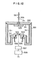
- Fig. 12 shows an RIE device incorporated in a sixth embodiment of the apparatus for producing semiconductor devices in accordance with the present invention.
- the top of a vacuum chamber 501 made of a stainless steel is air-tightly closed by a detachable cover 502 and a lower electrode 504 upon which is placed a wafer 503 is disposed on the bottom of the vacuum chamber 501.
- An upper electrode 505 which is grounded is securely attached to the undersurface of the detachable cover 502 by means of screws in opposed relationship with the lower electrode 504.
- the lower surface of the lower electrode 504 is communicated with cooling-water pipes 206 and the lower electrode 504 is connected through a matching circuit 507 to an RF power supply 508.
- a gas inlet pipe 509 with a valve 510 is extended through the upper electrode 505 to introduce the etching gases into the vacuum chamber 501.
- Aluminum linings 2 - 3 mm in thickness cover the inner wall surfaces of the vacuum chamber 501. These linings are divided into those which cover the side wall surfaces and the bottom and that which covers the undersurface of the cover 502 and which is securely interposed between the upper electrode 505 and the undersurface of the cover 502 when the upper electrode 505 is screwed into the detachable cover 502.
- the linings 511 can positively prevent the wafer 502 from being contaminated with iron, nickel and the like produced from the stainless steel component parts.
- the cover 502 is removed and the linings 511 are detached so that a period of time during which the interior of the vacuum chamber 501 is exposed to the surrounding atmosphere can be shortened.
- the etching process can be started again only by replacing the old linings 511 with new ones.
- linings made of any other suitable materials such as carbon, silicon carbide and the like may be used.
- the inner wall surfaces of the vacuum vessel of the plasma etching device in accordance with the present invention are lined with the aluminum linings which.are detachable so that even when the vacuum chamber is made of stainless steel and chloride etching gases are used, the contamination of wafers can be positively prevented. Furthermore, the maintenance such as cleaning can be carried out in a simple manner only by detaching the aluminum linings. Moreover, economical advantages can be obtained.
Landscapes
- Engineering & Computer Science (AREA)
- Robotics (AREA)
- Mechanical Engineering (AREA)
- Drying Of Semiconductors (AREA)
- Container, Conveyance, Adherence, Positioning, Of Wafer (AREA)
Applications Claiming Priority (10)
| Application Number | Priority Date | Filing Date | Title |
|---|---|---|---|
| JP253585/84 | 1984-11-30 | ||
| JP59253589A JPS61131522A (ja) | 1984-11-30 | 1984-11-30 | 半導体処理装置 |
| JP253591/84 | 1984-11-30 | ||
| JP253581/84 | 1984-11-30 | ||
| JP25359184A JPS61133388A (ja) | 1984-11-30 | 1984-11-30 | ドライエツチング装置 |
| JP25358584A JPS61133386A (ja) | 1984-11-30 | 1984-11-30 | プラズマエツチング装置 |
| JP253582/84 | 1984-11-30 | ||
| JP253589/84 | 1984-11-30 | ||
| JP25358284A JPS61133314A (ja) | 1984-11-30 | 1984-11-30 | 熱処理装置 |
| JP59253581A JPS61131532A (ja) | 1984-11-30 | 1984-11-30 | シ−ト状材料の熱処理装置 |
Publications (3)
| Publication Number | Publication Date |
|---|---|
| EP0187249A2 true EP0187249A2 (de) | 1986-07-16 |
| EP0187249A3 EP0187249A3 (en) | 1989-03-29 |
| EP0187249B1 EP0187249B1 (de) | 1994-05-18 |
Family
ID=27530261
Family Applications (1)
| Application Number | Title | Priority Date | Filing Date |
|---|---|---|---|
| EP85115144A Expired - Lifetime EP0187249B1 (de) | 1984-11-30 | 1985-11-29 | Apparat zur Herstellung von Halbleiteranordnungen |
Country Status (3)
| Country | Link |
|---|---|
| US (1) | US4693777A (de) |
| EP (1) | EP0187249B1 (de) |
| DE (1) | DE3587830T2 (de) |
Cited By (17)
| Publication number | Priority date | Publication date | Assignee | Title |
|---|---|---|---|---|
| FR2588120A1 (fr) * | 1985-10-01 | 1987-04-03 | Sgs Microelettronica Spa | Procede et appareil correspondant pour etablir des contacts de type ohmique entre un metal et un semi-conducteur |
| WO1987007078A1 (en) * | 1986-05-16 | 1987-11-19 | Eastman Kodak Company | Article transfer apparatus |
| EP0246798A3 (de) * | 1986-05-19 | 1988-07-27 | Machine Technology Inc. | Modulare Bearbeitungsvorrichtung zum Behandeln von Halbleiterplättchen |
| FR2610450A1 (fr) * | 1987-01-29 | 1988-08-05 | France Etat | Dispositif de traitement thermique de plaquettes semi-conductrices |
| WO1988009246A1 (en) * | 1987-05-18 | 1988-12-01 | Aeronca Electronics Inc. | Articulated arm transfer device |
| EP0306967A3 (de) * | 1987-09-11 | 1990-08-22 | Hitachi, Ltd. | Vorrichtung zur Durchführung einer Wärmebehandlung an Halbleiterplättchen |
| EP0385590A1 (de) * | 1989-02-27 | 1990-09-05 | Hitachi, Ltd. | Verfahren und Vorrichtung zur Behandlung von Proben |
| EP0343530A3 (de) * | 1988-05-24 | 1990-12-27 | Balzers Aktiengesellschaft | Vakuumanlage |
| EP0386337A3 (de) * | 1989-03-10 | 1991-01-16 | Applied Materials, Inc. | Mehrstufig planarisierte chemische Abscheidung aus der Gasphase |
| EP0408216A3 (en) * | 1989-07-11 | 1991-09-18 | Hitachi, Ltd. | Method for processing wafers and producing semiconductor devices and apparatus for producing the same |
| EP0494783A1 (de) * | 1991-01-10 | 1992-07-15 | Nec Corporation | Ofenstruktur einer Herstellungsvorrichtung für Halbleiter |
| EP0561300A1 (de) * | 1992-03-19 | 1993-09-22 | Texas Instruments Deutschland Gmbh | Anordnung zum Entfernen von Photolack von der Oberfläche von Halbleiterscheiben |
| EP0688041A1 (de) * | 1994-06-17 | 1995-12-20 | Dainippon Screen Mfg. Co., Ltd. | Substrat-Bearbeitungsvorrichtung |
| US5868854A (en) * | 1989-02-27 | 1999-02-09 | Hitachi, Ltd. | Method and apparatus for processing samples |
| WO1999060614A1 (en) * | 1998-05-18 | 1999-11-25 | Applied Materials, Inc. | A wafer buffer station and a method for a per-wafer transfer between work stations |
| US6077788A (en) * | 1989-02-27 | 2000-06-20 | Hitachi, Ltd. | Method and apparatus for processing samples |
| US6989228B2 (en) | 1989-02-27 | 2006-01-24 | Hitachi, Ltd | Method and apparatus for processing samples |
Families Citing this family (114)
| Publication number | Priority date | Publication date | Assignee | Title |
|---|---|---|---|---|
| JPS6218028A (ja) * | 1985-07-16 | 1987-01-27 | Toshiba Corp | デイスカム装置 |
| JPS6362233A (ja) * | 1986-09-03 | 1988-03-18 | Mitsubishi Electric Corp | 反応性イオンエツチング装置 |
| JPS63204726A (ja) * | 1987-02-20 | 1988-08-24 | Anelva Corp | 真空処理装置 |
| US4786616A (en) * | 1987-06-12 | 1988-11-22 | American Telephone And Telegraph Company | Method for heteroepitaxial growth using multiple MBE chambers |
| JPS6419198A (en) * | 1987-07-15 | 1989-01-23 | Hitachi Ltd | Vacuum pump |
| JP2768685B2 (ja) * | 1988-03-28 | 1998-06-25 | 株式会社東芝 | 半導体装置の製造方法及びその装置 |
| DE3814924A1 (de) * | 1988-05-03 | 1989-11-16 | Leybold Ag | Vorrichtung zum ein- und ausschleusen von substraten aus einem vakuumkessel |
| US5235995A (en) * | 1989-03-27 | 1993-08-17 | Semitool, Inc. | Semiconductor processor apparatus with dynamic wafer vapor treatment and particulate volatilization |
| US4911810A (en) * | 1988-06-21 | 1990-03-27 | Brown University | Modular sputtering apparatus |
| US4869198A (en) * | 1988-09-30 | 1989-09-26 | Union Tool Corporation | Vacuum debubbler machine |
| US5019233A (en) * | 1988-10-31 | 1991-05-28 | Eaton Corporation | Sputtering system |
| US5200017A (en) * | 1989-02-27 | 1993-04-06 | Hitachi, Ltd. | Sample processing method and apparatus |
| US5357991A (en) * | 1989-03-27 | 1994-10-25 | Semitool, Inc. | Gas phase semiconductor processor with liquid phase mixing |
| US5288333A (en) * | 1989-05-06 | 1994-02-22 | Dainippon Screen Mfg. Co., Ltd. | Wafer cleaning method and apparatus therefore |
| US5158100A (en) * | 1989-05-06 | 1992-10-27 | Dainippon Screen Mfg. Co., Ltd. | Wafer cleaning method and apparatus therefor |
| JPH07110991B2 (ja) * | 1989-10-02 | 1995-11-29 | 株式会社日立製作所 | プラズマ処理装置およびプラズマ処理方法 |
| DE69120446T2 (de) * | 1990-02-19 | 1996-11-14 | Canon Kk | Verfahren zum Herstellen von abgeschiedener Metallschicht, die Aluminium als Hauptkomponente enthält, mit Anwendung von Alkylaluminiumhydrid |
| CA2040989A1 (en) * | 1990-05-01 | 1991-11-02 | Ichiro Yoshida | Washing/drying method and apparatus |
| US6375741B2 (en) * | 1991-03-06 | 2002-04-23 | Timothy J. Reardon | Semiconductor processing spray coating apparatus |
| US5085727A (en) * | 1990-05-21 | 1992-02-04 | Applied Materials, Inc. | Plasma etch apparatus with conductive coating on inner metal surfaces of chamber to provide protection from chemical corrosion |
| JP2757546B2 (ja) * | 1990-08-27 | 1998-05-25 | 日本電気株式会社 | Feを含む物質のエッチング方法およびエッチング装置 |
| US5488964A (en) * | 1991-05-08 | 1996-02-06 | Tokyo Electron Limited | Washing apparatus, and washing method |
| US5343885A (en) * | 1992-03-04 | 1994-09-06 | Baxter International Inc. | Vacuum air lock for a closed perimeter solvent conservation system |
| US5313965A (en) * | 1992-06-01 | 1994-05-24 | Hughes Aircraft Company | Continuous operation supercritical fluid treatment process and system |
| AU4652993A (en) | 1992-06-26 | 1994-01-24 | Materials Research Corporation | Transport system for wafer processing line |
| US5449883A (en) * | 1992-08-07 | 1995-09-12 | Mitsubishi Materials Corporation | Continuous heat treatment system of semiconductor wafers for eliminating thermal donor |
| JP3172758B2 (ja) * | 1993-11-20 | 2001-06-04 | 東京エレクトロン株式会社 | プラズマエッチング方法 |
| US5798016A (en) * | 1994-03-08 | 1998-08-25 | International Business Machines Corporation | Apparatus for hot wall reactive ion etching using a dielectric or metallic liner with temperature control to achieve process stability |
| US5680013A (en) * | 1994-03-15 | 1997-10-21 | Applied Materials, Inc. | Ceramic protection for heated metal surfaces of plasma processing chamber exposed to chemically aggressive gaseous environment therein and method of protecting such heated metal surfaces |
| US6358631B1 (en) | 1994-12-13 | 2002-03-19 | The Trustees Of Princeton University | Mixed vapor deposited films for electroluminescent devices |
| US5703436A (en) | 1994-12-13 | 1997-12-30 | The Trustees Of Princeton University | Transparent contacts for organic devices |
| US5707745A (en) | 1994-12-13 | 1998-01-13 | The Trustees Of Princeton University | Multicolor organic light emitting devices |
| US6548956B2 (en) | 1994-12-13 | 2003-04-15 | The Trustees Of Princeton University | Transparent contacts for organic devices |
| US5672239A (en) * | 1995-05-10 | 1997-09-30 | Tegal Corporation | Integrated semiconductor wafer processing system |
| JPH0936198A (ja) * | 1995-07-19 | 1997-02-07 | Hitachi Ltd | 真空処理装置およびそれを用いた半導体製造ライン |
| US5954911A (en) * | 1995-10-12 | 1999-09-21 | Semitool, Inc. | Semiconductor processing using vapor mixtures |
| KR100218269B1 (ko) * | 1996-05-30 | 1999-09-01 | 윤종용 | 건식 에칭기의 잔류 가스 제거 장치 및 방법 |
| KR0183912B1 (ko) * | 1996-08-08 | 1999-05-01 | 김광호 | 다중 반응 챔버에 연결된 펌핑 설비 및 이를 사용하는 방법 |
| US6051421A (en) * | 1996-09-09 | 2000-04-18 | Air Liquide America Corporation | Continuous processing apparatus and method for cleaning articles with liquified compressed gaseous solvents |
| US6009890A (en) * | 1997-01-21 | 2000-01-04 | Tokyo Electron Limited | Substrate transporting and processing system |
| US6432203B1 (en) * | 1997-03-17 | 2002-08-13 | Applied Komatsu Technology, Inc. | Heated and cooled vacuum chamber shield |
| US6500605B1 (en) | 1997-05-27 | 2002-12-31 | Tokyo Electron Limited | Removal of photoresist and residue from substrate using supercritical carbon dioxide process |
| US6306564B1 (en) | 1997-05-27 | 2001-10-23 | Tokyo Electron Limited | Removal of resist or residue from semiconductors using supercritical carbon dioxide |
| TW539918B (en) | 1997-05-27 | 2003-07-01 | Tokyo Electron Ltd | Removal of photoresist and photoresist residue from semiconductors using supercritical carbon dioxide process |
| JP3737604B2 (ja) * | 1997-06-03 | 2006-01-18 | 大日本スクリーン製造株式会社 | 基板処理装置 |
| US6034000A (en) | 1997-07-28 | 2000-03-07 | Applied Materials, Inc. | Multiple loadlock system |
| US7393561B2 (en) * | 1997-08-11 | 2008-07-01 | Applied Materials, Inc. | Method and apparatus for layer by layer deposition of thin films |
| US6352593B1 (en) | 1997-08-11 | 2002-03-05 | Torrex Equipment Corp. | Mini-batch process chamber |
| US6167837B1 (en) | 1998-01-15 | 2001-01-02 | Torrex Equipment Corp. | Apparatus and method for plasma enhanced chemical vapor deposition (PECVD) in a single wafer reactor |
| US6352594B2 (en) | 1997-08-11 | 2002-03-05 | Torrex | Method and apparatus for improved chemical vapor deposition processes using tunable temperature controlled gas injectors |
| US6780464B2 (en) | 1997-08-11 | 2004-08-24 | Torrex Equipment | Thermal gradient enhanced CVD deposition at low pressure |
| WO1999036587A1 (en) * | 1998-01-15 | 1999-07-22 | Torrex Equipment Corporation | Vertical plasma enhanced process apparatus and method |
| US6277753B1 (en) | 1998-09-28 | 2001-08-21 | Supercritical Systems Inc. | Removal of CMP residue from semiconductors using supercritical carbon dioxide process |
| JP2000277584A (ja) * | 1999-03-26 | 2000-10-06 | Innotech Corp | 半導体デバイスの製造ライン |
| KR100744888B1 (ko) | 1999-11-02 | 2007-08-01 | 동경 엘렉트론 주식회사 | 소재를 초임계 처리하기 위한 장치 및 방법 |
| US6748960B1 (en) | 1999-11-02 | 2004-06-15 | Tokyo Electron Limited | Apparatus for supercritical processing of multiple workpieces |
| US6949143B1 (en) | 1999-12-15 | 2005-09-27 | Applied Materials, Inc. | Dual substrate loadlock process equipment |
| US6890853B2 (en) * | 2000-04-25 | 2005-05-10 | Tokyo Electron Limited | Method of depositing metal film and metal deposition cluster tool including supercritical drying/cleaning module |
| AU2001290171A1 (en) | 2000-07-26 | 2002-02-05 | Tokyo Electron Limited | High pressure processing chamber for semiconductor substrate |
| JP2004505698A (ja) * | 2000-08-08 | 2004-02-26 | エルジー エレクトロニクス インコーポレイティド | 洗濯機使用説明の表示方法および装置 |
| EP1319243A2 (de) * | 2000-09-15 | 2003-06-18 | Applied Materials, Inc. | Zweifachladungsschleusenvorrichtung mit doppelschlitz für prozessanlage |
| JP4100466B2 (ja) * | 2000-12-25 | 2008-06-11 | 東京エレクトロン株式会社 | 液処理装置 |
| DE10103111A1 (de) * | 2001-01-24 | 2002-08-01 | Mattson Wet Products Gmbh | Vorrichtung zum Behandeln von Substraten |
| WO2003021642A2 (en) * | 2001-08-31 | 2003-03-13 | Applied Materials, Inc. | Method and apparatus for processing a wafer |
| US20030045098A1 (en) * | 2001-08-31 | 2003-03-06 | Applied Materials, Inc. | Method and apparatus for processing a wafer |
| US7316966B2 (en) | 2001-09-21 | 2008-01-08 | Applied Materials, Inc. | Method for transferring substrates in a load lock chamber |
| US6998353B2 (en) * | 2001-11-05 | 2006-02-14 | Ibis Technology Corporation | Active wafer cooling during damage engineering implant to enhance buried oxide formation in SIMOX wafers |
| US7001468B1 (en) | 2002-02-15 | 2006-02-21 | Tokyo Electron Limited | Pressure energized pressure vessel opening and closing device and method of providing therefor |
| US7387868B2 (en) * | 2002-03-04 | 2008-06-17 | Tokyo Electron Limited | Treatment of a dielectric layer using supercritical CO2 |
| US7021635B2 (en) * | 2003-02-06 | 2006-04-04 | Tokyo Electron Limited | Vacuum chuck utilizing sintered material and method of providing thereof |
| US7077917B2 (en) | 2003-02-10 | 2006-07-18 | Tokyo Electric Limited | High-pressure processing chamber for a semiconductor wafer |
| US7225820B2 (en) * | 2003-02-10 | 2007-06-05 | Tokyo Electron Limited | High-pressure processing chamber for a semiconductor wafer |
| US7270137B2 (en) | 2003-04-28 | 2007-09-18 | Tokyo Electron Limited | Apparatus and method of securing a workpiece during high-pressure processing |
| US7226512B2 (en) * | 2003-06-18 | 2007-06-05 | Ekc Technology, Inc. | Load lock system for supercritical fluid cleaning |
| US7163380B2 (en) * | 2003-07-29 | 2007-01-16 | Tokyo Electron Limited | Control of fluid flow in the processing of an object with a fluid |
| US20050035514A1 (en) * | 2003-08-11 | 2005-02-17 | Supercritical Systems, Inc. | Vacuum chuck apparatus and method for holding a wafer during high pressure processing |
| US20050067002A1 (en) * | 2003-09-25 | 2005-03-31 | Supercritical Systems, Inc. | Processing chamber including a circulation loop integrally formed in a chamber housing |
| US7207766B2 (en) | 2003-10-20 | 2007-04-24 | Applied Materials, Inc. | Load lock chamber for large area substrate processing system |
| US7186093B2 (en) * | 2004-10-05 | 2007-03-06 | Tokyo Electron Limited | Method and apparatus for cooling motor bearings of a high pressure pump |
| US7497414B2 (en) | 2004-06-14 | 2009-03-03 | Applied Materials, Inc. | Curved slit valve door with flexible coupling |
| US7250374B2 (en) | 2004-06-30 | 2007-07-31 | Tokyo Electron Limited | System and method for processing a substrate using supercritical carbon dioxide processing |
| TW200633033A (en) * | 2004-08-23 | 2006-09-16 | Koninkl Philips Electronics Nv | Hot source cleaning system |
| US7461663B2 (en) * | 2004-09-01 | 2008-12-09 | Sanyo Electric Co., Ltd. | Cleaning apparatus |
| US7307019B2 (en) | 2004-09-29 | 2007-12-11 | Tokyo Electron Limited | Method for supercritical carbon dioxide processing of fluoro-carbon films |
| US20060065189A1 (en) * | 2004-09-30 | 2006-03-30 | Darko Babic | Method and system for homogenization of supercritical fluid in a high pressure processing system |
| US7491036B2 (en) | 2004-11-12 | 2009-02-17 | Tokyo Electron Limited | Method and system for cooling a pump |
| US7140393B2 (en) | 2004-12-22 | 2006-11-28 | Tokyo Electron Limited | Non-contact shuttle valve for flow diversion in high pressure systems |
| US7434590B2 (en) | 2004-12-22 | 2008-10-14 | Tokyo Electron Limited | Method and apparatus for clamping a substrate in a high pressure processing system |
| US7291565B2 (en) | 2005-02-15 | 2007-11-06 | Tokyo Electron Limited | Method and system for treating a substrate with a high pressure fluid using fluorosilicic acid |
| US7435447B2 (en) | 2005-02-15 | 2008-10-14 | Tokyo Electron Limited | Method and system for determining flow conditions in a high pressure processing system |
| US7767145B2 (en) * | 2005-03-28 | 2010-08-03 | Toyko Electron Limited | High pressure fourier transform infrared cell |
| US7380984B2 (en) * | 2005-03-28 | 2008-06-03 | Tokyo Electron Limited | Process flow thermocouple |
| US20060225772A1 (en) * | 2005-03-29 | 2006-10-12 | Jones William D | Controlled pressure differential in a high-pressure processing chamber |
| US7494107B2 (en) * | 2005-03-30 | 2009-02-24 | Supercritical Systems, Inc. | Gate valve for plus-atmospheric pressure semiconductor process vessels |
| JP4619854B2 (ja) * | 2005-04-18 | 2011-01-26 | 東京エレクトロン株式会社 | ロードロック装置及び処理方法 |
| US7789971B2 (en) | 2005-05-13 | 2010-09-07 | Tokyo Electron Limited | Treatment of substrate using functionalizing agent in supercritical carbon dioxide |
| US7524383B2 (en) | 2005-05-25 | 2009-04-28 | Tokyo Electron Limited | Method and system for passivating a processing chamber |
| US7845891B2 (en) | 2006-01-13 | 2010-12-07 | Applied Materials, Inc. | Decoupled chamber body |
| US7665951B2 (en) | 2006-06-02 | 2010-02-23 | Applied Materials, Inc. | Multiple slot load lock chamber and method of operation |
| US7845618B2 (en) | 2006-06-28 | 2010-12-07 | Applied Materials, Inc. | Valve door with ball coupling |
| US8124907B2 (en) | 2006-08-04 | 2012-02-28 | Applied Materials, Inc. | Load lock chamber with decoupled slit valve door seal compartment |
| US8082741B2 (en) * | 2007-05-15 | 2011-12-27 | Brooks Automation, Inc. | Integral facet cryopump, water vapor pump, or high vacuum pump |
| US9166139B2 (en) * | 2009-05-14 | 2015-10-20 | The Neothermal Energy Company | Method for thermally cycling an object including a polarizable material |
| DE102009035341A1 (de) * | 2009-07-23 | 2011-01-27 | Gebr. Schmid Gmbh & Co. | Vorrichtung zur Reinigung von Substraten an einem Träger |
| TW201137143A (en) * | 2010-04-28 | 2011-11-01 | Hon Hai Prec Ind Co Ltd | Sputtering system |
| KR101915753B1 (ko) * | 2010-10-21 | 2018-11-07 | 삼성디스플레이 주식회사 | 이온 주입 시스템 및 이를 이용한 이온 주입 방법 |
| US20130101372A1 (en) * | 2011-10-19 | 2013-04-25 | Lam Research Ag | Method and apparatus for processing wafer-shaped articles |
| TWI513811B (zh) * | 2011-10-27 | 2015-12-21 | Hon Hai Prec Ind Co Ltd | 自動解蠟裝置 |
| CN103096526B (zh) * | 2011-10-28 | 2016-06-29 | 鸿富锦精密工业(深圳)有限公司 | 自动解蜡装置 |
| US8998553B2 (en) | 2011-12-07 | 2015-04-07 | Intevac, Inc. | High throughput load lock for solar wafers |
| CN103236392B (zh) * | 2013-05-14 | 2015-04-22 | 哈尔滨工业大学 | 成型电极大气等离子体加工回转零件方法 |
| US9704714B2 (en) * | 2015-04-16 | 2017-07-11 | Taiwan Semiconductor Manufacturing Co., Ltd | Method for controlling surface charge on wafer surface in semiconductor fabrication |
| CN108417491A (zh) * | 2018-02-02 | 2018-08-17 | 武汉新芯集成电路制造有限公司 | 一种减少铝腐蚀的方法 |
| JP7175191B2 (ja) * | 2018-12-28 | 2022-11-18 | 株式会社Screenホールディングス | 基板処理装置および基板搬送方法 |
Family Cites Families (10)
| Publication number | Priority date | Publication date | Assignee | Title |
|---|---|---|---|---|
| US4376581A (en) * | 1979-12-20 | 1983-03-15 | Censor Patent- Und Versuchs-Anstalt | Method of positioning disk-shaped workpieces, preferably semiconductor wafers |
| JPS5713743A (en) * | 1980-06-30 | 1982-01-23 | Toshiba Corp | Plasma etching apparatus and etching method |
| JPS5723228A (en) * | 1980-07-16 | 1982-02-06 | Mitsubishi Electric Corp | Dry etching device |
| JPS5747876A (en) * | 1980-09-03 | 1982-03-18 | Toshiba Corp | Plasma etching apparatus and method |
| JPS5856336A (ja) * | 1981-09-29 | 1983-04-04 | Nec Corp | 複合ドライエツチング装置 |
| JPS58101478A (ja) * | 1981-12-12 | 1983-06-16 | Toshiba Corp | 多結晶シリコン太陽電池の製造方法 |
| JPS58196063A (ja) * | 1982-05-10 | 1983-11-15 | Matsushita Electric Ind Co Ltd | 光起電力素子の製造方法 |
| DE3381302D1 (de) * | 1982-12-16 | 1990-04-12 | Fujitsu Ltd | Herstellung eines halbleiterbauelementes mittels molekularstrahlepitaxie. |
| JPS59123226A (ja) * | 1982-12-28 | 1984-07-17 | Fujitsu Ltd | 半導体装置の製造装置 |
| JPS59186326A (ja) * | 1983-04-06 | 1984-10-23 | Hitachi Ltd | プラズマ処理装置 |
-
1985
- 1985-11-27 US US06/802,468 patent/US4693777A/en not_active Expired - Lifetime
- 1985-11-29 DE DE3587830T patent/DE3587830T2/de not_active Expired - Lifetime
- 1985-11-29 EP EP85115144A patent/EP0187249B1/de not_active Expired - Lifetime
Cited By (27)
| Publication number | Priority date | Publication date | Assignee | Title |
|---|---|---|---|---|
| FR2588120A1 (fr) * | 1985-10-01 | 1987-04-03 | Sgs Microelettronica Spa | Procede et appareil correspondant pour etablir des contacts de type ohmique entre un metal et un semi-conducteur |
| WO1987007078A1 (en) * | 1986-05-16 | 1987-11-19 | Eastman Kodak Company | Article transfer apparatus |
| EP0246798A3 (de) * | 1986-05-19 | 1988-07-27 | Machine Technology Inc. | Modulare Bearbeitungsvorrichtung zum Behandeln von Halbleiterplättchen |
| FR2610450A1 (fr) * | 1987-01-29 | 1988-08-05 | France Etat | Dispositif de traitement thermique de plaquettes semi-conductrices |
| WO1988009246A1 (en) * | 1987-05-18 | 1988-12-01 | Aeronca Electronics Inc. | Articulated arm transfer device |
| US5001327A (en) * | 1987-09-11 | 1991-03-19 | Hitachi, Ltd. | Apparatus and method for performing heat treatment on semiconductor wafers |
| EP0306967A3 (de) * | 1987-09-11 | 1990-08-22 | Hitachi, Ltd. | Vorrichtung zur Durchführung einer Wärmebehandlung an Halbleiterplättchen |
| EP0343530A3 (de) * | 1988-05-24 | 1990-12-27 | Balzers Aktiengesellschaft | Vakuumanlage |
| US6989228B2 (en) | 1989-02-27 | 2006-01-24 | Hitachi, Ltd | Method and apparatus for processing samples |
| US6537417B2 (en) | 1989-02-27 | 2003-03-25 | Hitachi, Ltd. | Apparatus for processing samples |
| US6537415B2 (en) | 1989-02-27 | 2003-03-25 | Hitachi, Ltd. | Apparatus for processing samples |
| US6254721B1 (en) | 1989-02-27 | 2001-07-03 | Hitachi, Ltd. | Method and apparatus for processing samples |
| EP0385590A1 (de) * | 1989-02-27 | 1990-09-05 | Hitachi, Ltd. | Verfahren und Vorrichtung zur Behandlung von Proben |
| US7132293B2 (en) | 1989-02-27 | 2006-11-07 | Hitachi, Ltd. | Method and apparatus for processing samples |
| EP0751552A1 (de) * | 1989-02-27 | 1997-01-02 | Hitachi, Ltd. | Vorrichtung zur Behandlung von Proben |
| US6077788A (en) * | 1989-02-27 | 2000-06-20 | Hitachi, Ltd. | Method and apparatus for processing samples |
| US5868854A (en) * | 1989-02-27 | 1999-02-09 | Hitachi, Ltd. | Method and apparatus for processing samples |
| US5952245A (en) * | 1989-02-27 | 1999-09-14 | Hitachi, Ltd. | Method for processing samples |
| US6656846B2 (en) | 1989-02-27 | 2003-12-02 | Hitachi, Ltd. | Apparatus for processing samples |
| US6036816A (en) * | 1989-02-27 | 2000-03-14 | Hitachi, Ltd. | Apparatus for processing a sample having a metal laminate |
| EP0386337A3 (de) * | 1989-03-10 | 1991-01-16 | Applied Materials, Inc. | Mehrstufig planarisierte chemische Abscheidung aus der Gasphase |
| EP0408216A3 (en) * | 1989-07-11 | 1991-09-18 | Hitachi, Ltd. | Method for processing wafers and producing semiconductor devices and apparatus for producing the same |
| EP0494783A1 (de) * | 1991-01-10 | 1992-07-15 | Nec Corporation | Ofenstruktur einer Herstellungsvorrichtung für Halbleiter |
| EP0561300A1 (de) * | 1992-03-19 | 1993-09-22 | Texas Instruments Deutschland Gmbh | Anordnung zum Entfernen von Photolack von der Oberfläche von Halbleiterscheiben |
| US5639301A (en) * | 1994-06-17 | 1997-06-17 | Dainippon Screen Mfg. Co., Ltd. | Processing apparatus having parts for thermal and non-thermal treatment of substrates |
| EP0688041A1 (de) * | 1994-06-17 | 1995-12-20 | Dainippon Screen Mfg. Co., Ltd. | Substrat-Bearbeitungsvorrichtung |
| WO1999060614A1 (en) * | 1998-05-18 | 1999-11-25 | Applied Materials, Inc. | A wafer buffer station and a method for a per-wafer transfer between work stations |
Also Published As
| Publication number | Publication date |
|---|---|
| EP0187249A3 (en) | 1989-03-29 |
| US4693777A (en) | 1987-09-15 |
| EP0187249B1 (de) | 1994-05-18 |
| DE3587830T2 (de) | 1994-09-22 |
| DE3587830D1 (de) | 1994-06-23 |
Similar Documents
| Publication | Publication Date | Title |
|---|---|---|
| US4693777A (en) | Apparatus for producing semiconductor devices | |
| US6007675A (en) | Wafer transfer system and method of using the same | |
| US5380682A (en) | Wafer processing cluster tool batch preheating and degassing method | |
| JP3218488B2 (ja) | 処理装置 | |
| JP3238432B2 (ja) | マルチチャンバ型枚葉処理装置 | |
| US4483651A (en) | Automatic apparatus for continuous treatment of leaf materials with gas plasma | |
| US5769952A (en) | Reduced pressure and normal pressure treatment apparatus | |
| US6332280B2 (en) | Vacuum processing apparatus | |
| KR0155158B1 (ko) | 종형 처리 장치 및 처리방법 | |
| KR890002837B1 (ko) | 연속 스퍼터 장치 | |
| KR100852952B1 (ko) | 기판 양면 처리장치 | |
| KR100406337B1 (ko) | 기판이송및처리시스템 | |
| US5788448A (en) | Processing apparatus | |
| WO1994014185A1 (en) | Wafer processing machine vacuum front end method and apparatus | |
| JPH05275519A (ja) | 多室型基板処理装置 | |
| EP0211292B1 (de) | Gerät für Molekularstrahlepitaxie | |
| WO2004079808A1 (ja) | 基板の処理システム及び半導体装置の製造方法 | |
| JP3587788B2 (ja) | 昇降式基板処理装置及びこれを備えた基板処理システム | |
| JP3543987B2 (ja) | 処理装置 | |
| JPS6286184A (ja) | プラズマエツチング装置 | |
| USRE39775E1 (en) | Vacuum processing operating method with wafers, substrates and/or semiconductors | |
| JPH03134176A (ja) | 真空処理装置用ユニット | |
| JPS61263127A (ja) | エツチング装置 | |
| JP2942388B2 (ja) | 半導体製造装置 | |
| JP3017132B2 (ja) | 処理装置及び処理方法 |
Legal Events
| Date | Code | Title | Description |
|---|---|---|---|
| PUAI | Public reference made under article 153(3) epc to a published international application that has entered the european phase |
Free format text: ORIGINAL CODE: 0009012 |
|
| 17P | Request for examination filed |
Effective date: 19851129 |
|
| AK | Designated contracting states |
Kind code of ref document: A2 Designated state(s): DE FR GB |
|
| PUAL | Search report despatched |
Free format text: ORIGINAL CODE: 0009013 |
|
| AK | Designated contracting states |
Kind code of ref document: A3 Designated state(s): DE FR GB |
|
| RHK1 | Main classification (correction) |
Ipc: H01J 37/18 |
|
| 17Q | First examination report despatched |
Effective date: 19910205 |
|
| RAP1 | Party data changed (applicant data changed or rights of an application transferred) |
Owner name: KABUSHIKI KAISHA SHIBAURA SEISAKUSHO Owner name: KABUSHIKI KAISHA TOSHIBA |
|
| GRAA | (expected) grant |
Free format text: ORIGINAL CODE: 0009210 |
|
| AK | Designated contracting states |
Kind code of ref document: B1 Designated state(s): DE FR GB |
|
| REF | Corresponds to: |
Ref document number: 3587830 Country of ref document: DE Date of ref document: 19940623 |
|
| ET | Fr: translation filed | ||
| PLBE | No opposition filed within time limit |
Free format text: ORIGINAL CODE: 0009261 |
|
| STAA | Information on the status of an ep patent application or granted ep patent |
Free format text: STATUS: NO OPPOSITION FILED WITHIN TIME LIMIT |
|
| 26N | No opposition filed | ||
| REG | Reference to a national code |
Ref country code: GB Ref legal event code: IF02 |
|
| PGFP | Annual fee paid to national office [announced via postgrant information from national office to epo] |
Ref country code: FR Payment date: 20041116 Year of fee payment: 20 |
|
| PGFP | Annual fee paid to national office [announced via postgrant information from national office to epo] |
Ref country code: DE Payment date: 20041123 Year of fee payment: 20 |
|
| PGFP | Annual fee paid to national office [announced via postgrant information from national office to epo] |
Ref country code: GB Payment date: 20041124 Year of fee payment: 20 |
|
| PG25 | Lapsed in a contracting state [announced via postgrant information from national office to epo] |
Ref country code: GB Free format text: LAPSE BECAUSE OF EXPIRATION OF PROTECTION Effective date: 20051128 |
|
| REG | Reference to a national code |
Ref country code: GB Ref legal event code: PE20 |