EP0187254A2 - Verrou pour la benne basculante d'un véhicule - Google Patents
Verrou pour la benne basculante d'un véhicule Download PDFInfo
- Publication number
- EP0187254A2 EP0187254A2 EP85115204A EP85115204A EP0187254A2 EP 0187254 A2 EP0187254 A2 EP 0187254A2 EP 85115204 A EP85115204 A EP 85115204A EP 85115204 A EP85115204 A EP 85115204A EP 0187254 A2 EP0187254 A2 EP 0187254A2
- Authority
- EP
- European Patent Office
- Prior art keywords
- spring
- clamping claw
- low
- bolt
- fork
- Prior art date
- Legal status (The legal status is an assumption and is not a legal conclusion. Google has not performed a legal analysis and makes no representation as to the accuracy of the status listed.)
- Withdrawn
Links
Images

Classifications
-
- E—FIXED CONSTRUCTIONS
- E05—LOCKS; KEYS; WINDOW OR DOOR FITTINGS; SAFES
- E05C—BOLTS OR FASTENING DEVICES FOR WINGS, SPECIALLY FOR DOORS OR WINDOWS
- E05C19/00—Other devices specially designed for securing wings, e.g. with suction cups
- E05C19/02—Automatic catches, i.e. released by pull or pressure on the wing
- E05C19/024—Automatic catches, i.e. released by pull or pressure on the wing with a bifurcated latch
-
- Y—GENERAL TAGGING OF NEW TECHNOLOGICAL DEVELOPMENTS; GENERAL TAGGING OF CROSS-SECTIONAL TECHNOLOGIES SPANNING OVER SEVERAL SECTIONS OF THE IPC; TECHNICAL SUBJECTS COVERED BY FORMER USPC CROSS-REFERENCE ART COLLECTIONS [XRACs] AND DIGESTS
- Y10—TECHNICAL SUBJECTS COVERED BY FORMER USPC
- Y10T—TECHNICAL SUBJECTS COVERED BY FORMER US CLASSIFICATION
- Y10T292/00—Closure fasteners
- Y10T292/08—Bolts
- Y10T292/0876—Double acting
- Y10T292/0883—Swinging
Definitions
- the invention relates to a low-tension device for the tipping body of a vehicle, which has a locking element on the body side and a lever arrangement under the tension of a spring on the vehicle side, which can be pivoted by the locking element and the spring between a release and a low-tension position
- Tipping bodies attached to vehicles can usually be tipped about a horizontal axis located at the rear with the aid of a hydraulic cylinder which acts on the front end of the tipping body.
- tipping bodies which can alternatively or additively be tipped about a laterally running longitudinal axis.
- One of these known low-tensioning devices has a rubber block with a central bore which is fastened to the vehicle frame by means of a shell and a bolt and into which a spherical pin fastened to the tilting structure is to engage.
- the recess in the rubber block is also spherical, so that the rubber grips around the spherical dome and holds it in position.
- the problem here is that the position of the spherical dome changes over time as a result of general wear and tear and bends and is therefore not safe in the recess of the rubber block intervenes, but increasingly destroys it.
- Another known device works with a hook on the tipper body, a double lever fixed to the vehicle and a tensioning lever acting on it, which in turn is pretensioned into a closed position by means of a tension spring.
- a shock absorber is arranged parallel to the spring and rigidly bridges the spring when short impacts occur.
- This device works such that the hook sinking when the tipper body is lowered rotates the double lever which is initially in its release position, namely into a recess in the hook. The tensioning lever then presses the double lever into the closed position and holds it there under the spring force.
- the interlocking parts will not have their desired position when lowering due to after-wear and bending, so that destruction is to be feared here too.
- Even without age-related signs of wear difficulties occurred when engaging, particularly if the vehicle was on uneven ground and the frame and tipper body were warped or twisted differently.
- a disadvantage of this device are the production costs, which result from the necessary number of components and their exact installation.
- the object of the invention was to provide a low-tensioning device which can be produced at comparatively low costs, which has a low installation height and which, in particular, manages with few parts which are not susceptible to wear.
- the locking element is a locking bolt and the lever arrangement is formed by a clamping claw which has a fork and can be pivoted about a transverse axis approximately parallel to the locking bolt between two positions, in one of which the Fork opening in the direction of the locking bolt and in the other a nose of the fork lies in the way of the locking bolt; that the spring is a compression spring which on the one hand articulates on the clamping claw on the side of the transverse axis which is opposite the fork and on the other hand is articulated on the vehicle and that the line of action of the compression spring when pivoting the clamping claw through the transverse axis and the compression spring articulation axis Moving (bolt) connecting plane
- a stop on the vehicle side is provided to define the release position of the clamping claw and the articulation point of the spring on the clamping claw is provided at a point which, when the clamping claw is in contact with the stop, is on one side of said plane and in the low-clamping position standing claw is on the other side of this level
- the stop is formed by a web which extends parallel to the transverse axis between two plates of a bearing block supporting the clamping claw or that the stop is formed by a base plate supporting the clamping claw and the spring against which the surface of the Spring in the release position.
- the pivoting angle of the clamping claw between its release and its low clamping position is approximately 45 °
- the clear distance between the lugs forming the fork of the clamping claw is greater than the diameter of the locking bolt over its entire depth.
- the lugs forming the fork of the clamping claw are of different lengths and the nose adjacent to the base plate in the low-clamping position of the base plate is longer than the other nose, and that the locking bolt has an axial length that exceeds the thickness of the clamping claw in the region of its fork by at least twice.
- the end of the spring facing away from the clamping claw carries a bushing in an arrangement parallel to the transverse axis, which surrounds a vehicle-mounted bolt held in a bearing block.
- the end of the spring facing away from the clamping claw is provided with a fork which is supported on a bolt arranged axially parallel to the transverse axis, which in turn is held in a bearing block on the vehicle side
- the spring is a hollow rubber spring or the like. has, which is clamped between two adjustable in their clear plates; one of the plates is articulated by means of a shoulder and a cross bolt on the clamping claw and the like with one in the cavity of the rubber hollow spring.
- protruding tube is provided, which receives an at least partially threaded rod longitudinally displaceable, which passes through a central bore of the other plate, or the like on the outside of the hollow rubber spring.
- lying End is connected to the socket / fork and on which the rubber hollow spring or the like.
- opposite side of the plate carries a nut that forms an adjustable stop for the plate
- the basic idea of the solution according to the invention consists in the use of a clamping claw rotatable about a vehicle-fixed axle, which has two lugs on one side of this axle to form a fork and on the other side of which an adjustable compression spring arrangement with at least one over-center position is provided is, which forms a rear extension of the recess of the clamping claw in terms of their arrangement.
- This not only achieves a low overall height, but also the number of wear elements is kept lower than was previously the case with generic devices.
- the risk of breakage is also lower compared to the prior art because the interacting parts of the vehicle and the body have to be aligned less precisely than before.
- the large range of the automatic readjustment of the device in its low-tension position caused by the spring is particularly advantageous.
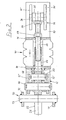
- each bracket On a base plate 10 used for connection to a vehicle, two bearing blocks 12, 14 are fastened in the region of its two ends.
- Each bracket consists of two parallel spaced plates 12 ', 12 "and 14', 14".
- the bearing block 12 has a transverse bore 16 passing through its two plates 12 ', 12 ".
- a bolt 18 is held in this transverse bore with play, which in the exemplary embodiment is fixed in the axial direction with the aid of split pins 20.
- a clamping claw 22 is rotatably mounted on the bolt 18 and laterally fixed by means of the two plates 12 ', 12 ".
- the clamping claw 22 has two lugs 24, 26 which delimit a recess 28 between them.
- the lugs show 24, 26 either upwards, ie away from the base plate 10 or to the left (in FIG. 1), ie in the direction opposite to the other bearing block 14.
- the clamping claw 22 is shown in two positions in FIG Lines correspond to the low-tension position, from which the tensioning claw can be pivoted in the direction of arrow 30 into a release position, in which the tensioning claw is shown with dash-dotted lines, as shown in the drawing, the lower of the two lugs 26 in the tensioned position, viewed from the bolt 18, is longer than the other nose 24. The usefulness of this difference will become clear below.
- the clamping claw 22 Viewed from the recess 28 of the clamping claw 22, the clamping claw is penetrated by a transverse bolt 32 beyond the bolt 18.
- the clear distance of the cross bolt 32 relative to the plate 10 in the low-tensioning position of the clamping claw 22 is greater than the corresponding clear distance of the bolt 18.
- the clamping claw 22 is configured accordingly to enable this clear distance, as is also the drawing reveals.
- the height of the cross bolt 32 above the base plate 10 with respect to the height of the bolt 18 is chosen so that the cross bolt 32 is after the rotation of the clamping claw 22 in its release position (shown in broken lines) at a closer distance from the base plate 1 0 than the other pin 18. In this way, the goal of these design rules is achieved, namely an over-center bearing of the clamping claw 22.
- this further bolt 36 has the same clear distance from the base plate 10 as the bolt 18 carrying the clamping claw 22. This height of the bolt 36 is also related to be seen with the desired over-center position of the clamping claw, that is to say in connection with the distances between the two other bolts from one another and from the base plate 10.
- the spring arrangement 4 0 is an adjustable in its spring force spring.
- it has a rubber hollow spring 42 as a spring element, which is known per se and is available with various non-linear spring characteristics. 2
- the rubber hollow spring 42 is clamped between two spaced plates 44, 46, of which the plate 44 carries a fork-shaped extension 48 which engages over the end of the clamping claw 22 facing the bearing block 14 and has bores through which the cross bolt 32 passes extends.
- This cross bolt is otherwise secured according to FIG. 1 with split pins 50 and passes through the bores of the projection 48 with play, as can be seen from FIG. 2.
- a tube 52 extends from the surface of the plate 44 opposite the shoulder, which points in the direction of the other plate 46 and projects into the cavity of the rubber hollow spring 42.
- This tube 52 is used for the longitudinal guidance of an at least partially threaded rod 54.
- One end of this rod is located inside the tube 52.
- the other end is connected to the bushing 34 or the fork 35.
- the rod 54 is screwed into the socket 34 or (fork 35) and secured by means of a lock nut 56. It goes without saying that a welded connection or the like serves the same purpose at this point.
- the rod 54 passes through a central bore of the plate 46 with play and carries, adjacent to the lock nut 56, a stop nut 58 which is screwed onto an external thread of the rod 54.
- the stop nut 58 serves on the one hand to facilitate the assembly of the spring arrangement 40 and on the other hand to adjust the spring force, as is clear from the following consideration.
- the rod 54 can be pushed far into the tube 52 without first exerting a force on the hollow rubber spring 4 2.
- the spring arrangement 40 can be conveniently arranged on the two bolts 32 and 36, respectively. If you now tighten the stop nut, it presses the plate 46 in the direction of the fixed plate 4 4 , whereby the rubber hollow spring 42 is compressed and biased.
- the above-mentioned game between the holes and bolts becomes meaningless after adjusting the spring preload. On the other hand, it contributes to a considerable reduction in the cost of production.
- Fig. 1 it can be seen that the spring assembly 40 presses the clamping claw 22 in the dot-dash release position of the clamping claw against a stop 60 located between the plate 12 ', 12 ", in which the of the lugs 24, 26 and Recess 28 formed fork at an angle of about 45 ° upwards, ie points away from the base plate
- bracket 70 which consists of two spaced plates 71, 72, between which a locking bolt 73 is welded or the like. is. Its axis runs essentially parallel to the axis of the pin 18. However, the parallelism is not particularly important. It should also be emphasized at this point that the designer is practically not limited in the choice of the length of the locking bolt 73 and can, for example, design the various interacting parts according to FIG.
- the locking bolt 73 moves a small distance into the upward-facing recess 28 of the clamping claw 22 and lies against the inner surface of the nose 26.
- the locking bolt 73 presses the nose 26 down, whereby the clamping claw 22 moves in the direction of arrow 30 in the counterclockwise direction and lifts off the stop 60.
- the spring arrangement 40 additionally presses the clamping claw 22 into the locking position, as a result of which the structure due to the force of the spring arrangement 40 against a vehicle-fixed but not shown stop is pulled and clamped. All involved elements of the device are now under the pressure of the spring arrangement 4 0, so that a rattling of the structure is excluded.
- the basic idea of the low-tensioning device lies in the use of a fork-like tensioning claw 22 which is prestressed by a compression spring 40, 42 and which can be rotated about the bolt 18, the compression spring arrangement 40 on the tensioning claw on one side of the bolt 18 attacks and the fork formed by the lugs 24, 26 is on the other side of this pin 18.
Landscapes
- Engineering & Computer Science (AREA)
- Mechanical Engineering (AREA)
- Forklifts And Lifting Vehicles (AREA)
- Springs (AREA)
- Vehicle Cleaning, Maintenance, Repair, Refitting, And Outriggers (AREA)
Applications Claiming Priority (2)
| Application Number | Priority Date | Filing Date | Title |
|---|---|---|---|
| DE3444804 | 1984-12-08 | ||
| DE19843444804 DE3444804A1 (de) | 1984-12-08 | 1984-12-08 | Niederspannvorrichtung fuer den kippaufbau eines fahrzeuges |
Publications (2)
| Publication Number | Publication Date |
|---|---|
| EP0187254A2 true EP0187254A2 (fr) | 1986-07-16 |
| EP0187254A3 EP0187254A3 (fr) | 1988-03-23 |
Family
ID=6252232
Family Applications (1)
| Application Number | Title | Priority Date | Filing Date |
|---|---|---|---|
| EP19850115204 Withdrawn EP0187254A3 (fr) | 1984-12-08 | 1985-11-30 | Verrou pour la benne basculante d'un véhicule |
Country Status (5)
| Country | Link |
|---|---|
| US (1) | US4690232A (fr) |
| EP (1) | EP0187254A3 (fr) |
| CA (1) | CA1259362A (fr) |
| DE (1) | DE3444804A1 (fr) |
| ES (1) | ES8704129A1 (fr) |
Families Citing this family (9)
| Publication number | Priority date | Publication date | Assignee | Title |
|---|---|---|---|---|
| DE3802254A1 (de) * | 1988-01-27 | 1989-08-24 | Kloeckner Ferromatik Desma | Verfahren zum steuern bzw. regeln von spritzgiessmaschinen |
| US4979766A (en) * | 1989-01-30 | 1990-12-25 | The Hartwell Corporation | Panel latch assembly |
| US6910731B2 (en) | 2002-12-19 | 2005-06-28 | Clark Equipment Company | Skid steer loader with front pivoting cab having a no tool latch |
| KR101100501B1 (ko) * | 2004-05-20 | 2011-12-29 | 엘지전자 주식회사 | 식기 세척기의 도어 잠금장치 |
| GB0505612D0 (en) * | 2005-03-21 | 2005-04-27 | Goodrich Actuation Systems Ltd | Lock arrangement |
| US8136272B2 (en) * | 2005-07-13 | 2012-03-20 | Harnischfeger Technologies, Inc. | Dipper door latch with locking mechanism |
| US8590180B2 (en) * | 2005-07-13 | 2013-11-26 | Harnischfeger Technologies, Inc. | Dipper door latch with locking mechanism |
| US20070107269A1 (en) * | 2005-07-13 | 2007-05-17 | Harnischfeger Technologies, Inc. | Dipper door latch with locking mechanism |
| US20140319850A1 (en) * | 2013-03-15 | 2014-10-30 | Securitech Group, Inc. | Magnetic door lock assembly |
Family Cites Families (11)
| Publication number | Priority date | Publication date | Assignee | Title |
|---|---|---|---|---|
| DE130646C (fr) * | ||||
| US2833578A (en) * | 1956-11-14 | 1958-05-06 | Nat Lock Co | Refrigerator latch mechanism |
| US3105266A (en) * | 1961-01-05 | 1963-10-01 | Proctor & Schwartz Inc | Combination latch and hinge |
| US3122796A (en) * | 1962-11-13 | 1964-03-03 | Gen Electric | Refrigerator door including latch supporting means |
| US3492038A (en) * | 1967-12-18 | 1970-01-27 | Schlage Lock Co | Double-acting door pull lock |
| US3506292A (en) * | 1968-06-17 | 1970-04-14 | Gen Electric | Refrigerator door latch |
| US3542430A (en) * | 1968-09-03 | 1970-11-24 | Daniel K Mavroff | Tilt bed trailer safety hitch |
| DE1953088C3 (de) * | 1969-10-22 | 1974-02-21 | Daimler-Benz Ag, 7000 Stuttgart | Vorrichtung zum Verriegeln eines kippbaren Fahrerhauses mit dem Fahrgestell |
| US3659886A (en) * | 1970-05-01 | 1972-05-02 | Sealth Aero Marine Co | Aircraft panels with precisely adjustable and easy action spring toggle latch |
| US3713681A (en) * | 1971-08-27 | 1973-01-30 | Coleman Co | Safety latch assembly for picnic coolers |
| US3823976A (en) * | 1972-05-01 | 1974-07-16 | Int Harvester Co | Latch mechanism |
-
1984
- 1984-12-08 DE DE19843444804 patent/DE3444804A1/de not_active Withdrawn
-
1985
- 1985-11-30 EP EP19850115204 patent/EP0187254A3/fr not_active Withdrawn
- 1985-12-06 US US06/805,883 patent/US4690232A/en not_active Expired - Fee Related
- 1985-12-06 ES ES549680A patent/ES8704129A1/es not_active Expired
- 1985-12-06 CA CA000497111A patent/CA1259362A/fr not_active Expired
Also Published As
| Publication number | Publication date |
|---|---|
| EP0187254A3 (fr) | 1988-03-23 |
| DE3444804A1 (de) | 1986-06-12 |
| ES8704129A1 (es) | 1987-04-01 |
| CA1259362A (fr) | 1989-09-12 |
| US4690232A (en) | 1987-09-01 |
| ES549680A0 (es) | 1987-04-01 |
Similar Documents
| Publication | Publication Date | Title |
|---|---|---|
| DE4221003C2 (de) | Hilfsvorrichtung zum Öffnen/Schließen für eine ladedeckseitige Platte | |
| DE10221311B4 (de) | Niederhub-Flurförderzeug | |
| DE818456C (de) | Radaufhaengung, insbesondere fuer die Lagerung eines Fahrzeuges | |
| EP0187254A2 (fr) | Verrou pour la benne basculante d'un véhicule | |
| EP0001112B1 (fr) | Dispositif de verrouillage de ridelles de camions | |
| DE3807273C1 (fr) | ||
| DE102009030633A1 (de) | Achseinbindung für gefederte Fahrzeugachsen sowie Platte zum Einbinden einer Fahrzeugachse | |
| EP0961726A1 (fr) | Systeme de relevage d'axe de vehicule a suspension pneumatique | |
| DE19748117C2 (de) | Kugelzapfen | |
| EP0149842B1 (fr) | Outil pour l'échange des cartouches d'amortisseurs | |
| DE3333231A1 (de) | Anordnung zur laengenverstellung einer zuggabel fuer einen fahrzeuganhaenger | |
| EP0388363B1 (fr) | Attelage pour véhicules | |
| EP0298471B1 (fr) | Protection anti-encastrement pour la partie arrière d'un véhicule à benne basculante ayant une structure basculable autour d'un axe transversal arrière | |
| DE102004011292A1 (de) | Achsaufhängung und Federplatte für eine Achsanbindung | |
| DE4325567C2 (de) | Geräteanbauvorrichtung und Arbeitsfahrzeug mit Geräteanbauvorrichtung | |
| DD244316A5 (de) | Verankerungssystem fuer starre achsen von fahrzeugen mit staarr an dem fahrgestell befestigten, vertikal beweglichen aufhaengungen | |
| DE2723073C2 (fr) | ||
| DE3028007C2 (de) | Knickgelenktes Fahrzeug | |
| DE69302734T2 (de) | Kippvorrichtung für einen Behälter, der drehbar auf einem Fahrzeugrahmen montiert ist | |
| EP0583597B1 (fr) | Articulation pour un essieu avant rigide, en particulier pour véhicules utilitaires | |
| EP1782972A1 (fr) | Attelage de remorque pour un véhicule tracteur, notamment pour un tracteur agricole | |
| DE1937171C3 (de) | Stabilisierungsvorrichtung für die Verbindung von Motorwagen und Anhänger | |
| DE4323808C2 (de) | Lager für Rad-Führungslenker zur Einstellung des Sturzes und Nachlaufes von Fahrzeugrädern | |
| DE8522360U1 (de) | Containerverriegelung | |
| DE1755290C3 (de) | Stabilisierend wirkende Starrachsaufhängung für Fahrzeuge |
Legal Events
| Date | Code | Title | Description |
|---|---|---|---|
| PUAI | Public reference made under article 153(3) epc to a published international application that has entered the european phase |
Free format text: ORIGINAL CODE: 0009012 |
|
| AK | Designated contracting states |
Kind code of ref document: A2 Designated state(s): AT BE CH DE FR GB IT LI LU NL SE |
|
| PUAL | Search report despatched |
Free format text: ORIGINAL CODE: 0009013 |
|
| AK | Designated contracting states |
Kind code of ref document: A3 Designated state(s): AT BE CH DE FR GB IT LI LU NL SE |
|
| STAA | Information on the status of an ep patent application or granted ep patent |
Free format text: STATUS: THE APPLICATION IS DEEMED TO BE WITHDRAWN |
|
| 18D | Application deemed to be withdrawn |
Effective date: 19880924 |
|
| RIN1 | Information on inventor provided before grant (corrected) |
Inventor name: SCHULZ, GERD |