EP0187319A1 - Tape guiding device for tape conveying devices, particularly magnetic tape devices, and tape cassettes provided therewith - Google Patents
Tape guiding device for tape conveying devices, particularly magnetic tape devices, and tape cassettes provided therewith Download PDFInfo
- Publication number
- EP0187319A1 EP0187319A1 EP85116041A EP85116041A EP0187319A1 EP 0187319 A1 EP0187319 A1 EP 0187319A1 EP 85116041 A EP85116041 A EP 85116041A EP 85116041 A EP85116041 A EP 85116041A EP 0187319 A1 EP0187319 A1 EP 0187319A1
- Authority
- EP
- European Patent Office
- Prior art keywords
- tape
- guide
- holding element
- base body
- guide band
- Prior art date
- Legal status (The legal status is an assumption and is not a legal conclusion. Google has not performed a legal analysis and makes no representation as to the accuracy of the status listed.)
- Granted
Links
- 235000014443 Pyrus communis Nutrition 0.000 claims abstract description 3
- 239000004793 Polystyrene Substances 0.000 claims description 4
- 229920002223 polystyrene Polymers 0.000 claims description 3
- 239000012858 resilient material Substances 0.000 claims description 3
- 238000001746 injection moulding Methods 0.000 claims description 2
- 239000011888 foil Substances 0.000 abstract description 27
- 239000002184 metal Substances 0.000 abstract description 27
- 238000004519 manufacturing process Methods 0.000 abstract description 7
- 239000000463 material Substances 0.000 description 10
- 239000004033 plastic Substances 0.000 description 5
- 229920003023 plastic Polymers 0.000 description 5
- 238000000034 method Methods 0.000 description 4
- 238000005452 bending Methods 0.000 description 3
- 230000033001 locomotion Effects 0.000 description 3
- 238000003754 machining Methods 0.000 description 3
- 241000220324 Pyrus Species 0.000 description 2
- 239000000654 additive Substances 0.000 description 2
- 238000013461 design Methods 0.000 description 2
- 238000003780 insertion Methods 0.000 description 2
- 230000037431 insertion Effects 0.000 description 2
- 238000012986 modification Methods 0.000 description 2
- 230000004048 modification Effects 0.000 description 2
- 238000005498 polishing Methods 0.000 description 2
- 239000010935 stainless steel Substances 0.000 description 2
- 229910001220 stainless steel Inorganic materials 0.000 description 2
- 238000012360 testing method Methods 0.000 description 2
- OKTJSMMVPCPJKN-UHFFFAOYSA-N Carbon Chemical compound [C] OKTJSMMVPCPJKN-UHFFFAOYSA-N 0.000 description 1
- 239000004962 Polyamide-imide Substances 0.000 description 1
- 239000004697 Polyetherimide Substances 0.000 description 1
- 239000004734 Polyphenylene sulfide Substances 0.000 description 1
- 229910000639 Spring steel Inorganic materials 0.000 description 1
- 229910000831 Steel Inorganic materials 0.000 description 1
- 229910045601 alloy Inorganic materials 0.000 description 1
- 239000000956 alloy Substances 0.000 description 1
- 230000009286 beneficial effect Effects 0.000 description 1
- 239000000919 ceramic Substances 0.000 description 1
- 238000010276 construction Methods 0.000 description 1
- 238000005260 corrosion Methods 0.000 description 1
- 230000007797 corrosion Effects 0.000 description 1
- 238000011161 development Methods 0.000 description 1
- 230000018109 developmental process Effects 0.000 description 1
- 230000002349 favourable effect Effects 0.000 description 1
- 229910002804 graphite Inorganic materials 0.000 description 1
- 239000010439 graphite Substances 0.000 description 1
- 238000002347 injection Methods 0.000 description 1
- 239000007924 injection Substances 0.000 description 1
- 238000009434 installation Methods 0.000 description 1
- 230000001050 lubricating effect Effects 0.000 description 1
- 239000002991 molded plastic Substances 0.000 description 1
- 235000021017 pears Nutrition 0.000 description 1
- 239000002985 plastic film Substances 0.000 description 1
- 229920006255 plastic film Polymers 0.000 description 1
- 238000007747 plating Methods 0.000 description 1
- 229920002492 poly(sulfone) Polymers 0.000 description 1
- 229920002312 polyamide-imide Polymers 0.000 description 1
- 229920001601 polyetherimide Polymers 0.000 description 1
- 229920000069 polyphenylene sulfide Polymers 0.000 description 1
- 238000012805 post-processing Methods 0.000 description 1
- 238000007781 pre-processing Methods 0.000 description 1
- 238000012545 processing Methods 0.000 description 1
- 238000005096 rolling process Methods 0.000 description 1
- 239000007787 solid Substances 0.000 description 1
- 238000005507 spraying Methods 0.000 description 1
- 239000010959 steel Substances 0.000 description 1
- 230000003746 surface roughness Effects 0.000 description 1
- 238000004381 surface treatment Methods 0.000 description 1
- 238000003466 welding Methods 0.000 description 1
Images




Classifications
-
- G—PHYSICS
- G11—INFORMATION STORAGE
- G11B—INFORMATION STORAGE BASED ON RELATIVE MOVEMENT BETWEEN RECORD CARRIER AND TRANSDUCER
- G11B23/00—Record carriers not specific to the method of recording or reproducing; Accessories, e.g. containers, specially adapted for co-operation with the recording or reproducing apparatus ; Intermediate mediums; Apparatus or processes specially adapted for their manufacture
- G11B23/02—Containers; Storing means both adapted to cooperate with the recording or reproducing means
- G11B23/04—Magazines; Cassettes for webs or filaments
- G11B23/041—Details
- G11B23/047—Guiding means
-
- G—PHYSICS
- G11—INFORMATION STORAGE
- G11B—INFORMATION STORAGE BASED ON RELATIVE MOVEMENT BETWEEN RECORD CARRIER AND TRANSDUCER
- G11B15/00—Driving, starting or stopping record carriers of filamentary or web form; Driving both such record carriers and heads; Guiding such record carriers or containers therefor; Control thereof; Control of operating function
- G11B15/60—Guiding record carrier
- G11B15/605—Guiding record carrier without displacing the guiding means
Definitions
- the invention relates to a tape guide device for tape transport devices, in particular magnetic tape devices, and magnetic tape cassettes, consisting of a flexible guide tape which rests on an at least partially dimensionally stable base body with a defined surface and forms the guide surface for the magnetic tape.
- tape guides in particular fixed guides, for thin, flexible, smooth, strip-shaped tapes, in particular magnetic tapes in cassettes and / or devices for holding or for low-friction and damage-free guiding of the tapes during all movement processes. e.g. when rewinding, during recording or playback operations, the tape is known.
- tape guides have become known from DE-OS 28 17 318, which consist of metallic hollow cylindrical bodies which are bent from a sheet metal strip and which are designed with at least one incision for engaging an extension of the cassette housing.
- the production of this hollow cylinder from the sheet metal strip does not offer any significant functional or economic advantages.
- Possible partial machining of the surface of the hollow cylinder body is also not advisable, since with small diameter guide elements with known processing machines (e.g. devices for centerless grinding) a cylinder surface can be closed more easily and quickly edit is as part of it.
- DE-PS 2 535 276 a large-area tape guide, which consists of a solid base body and a spring-elastic and attached to it deformed in Hook's area and fastened under tensile stress metal strips. The attachment under tensile stress takes place in order to form a concave guide surface for the magnetic tape.
- a curved guide surface is also to be formed using a sufficiently thin strip material "for which the surface of the base body must be suitably shaped so that the strip conforms to it in the desired manner in a tensioned position". Practically, this strip is made of V2A steel and has a thickness in the range of. 0.4 mm (400 ⁇ m).
- the invention is also intended to provide tape cassettes with such tape guide devices.
- the object is achieved with a tape guide device or a tape cassette of the type defined in the introduction that the guide tape has a greater length than the length of the circumferential contour of the base body and the thickness of the guide tape is at most about 150 microns, so that the shape of the guide surface exclusively is determined by the shape and / or the shape of the surface of the base body, and that at least one dimensionally stable holding element is provided for the torsion-proof mounting of the projecting end sections of the guide band.
- a thickness of the guide band in the range between approximately 10 ⁇ m and 50 ⁇ m is expedient.
- the guide band can consist of a resilient material.
- the guide band can be held on the base body and / or on the holding element by means of clamping.
- the base body is expediently at least partially designed with a cylindrical surface.
- the holding element can simply be designed with a slot or groove, in particular as a slotted cylinder body, for receiving the end sections of the guide band. It is also possible to use two holding projections arranged next to one another at a distance. If the tape transport device is a tape cassette, the holding element can at least partially consist of a housing wall. The holding elements in the cassette are expediently injection molded onto the cassette housing.
- the end sections of the guide band can be connected to one another, which, after manufacture, enables simple insertion into the holding element or elements.
- the end sections can also be connected in such a way that each end section is curved away from the longitudinal axis, which makes it easier to clamp them on the holding element.
- a guide band with an omega cross-sectional shape is advantageous, but a drop or pear shape in the inserted position is also favorable.
- the end sections of the guide band are provided with fastening openings, which makes it easy to fasten the guide band to the cylinder body.
- the cylinder body is designed with a fastening slot. which can also be used to prevent rotation.
- the cylinder body is made as a separate part and consists in particular of polystyrene.
- the cylinder body which can be manufactured as a mass part, can thus be produced very economically.
- a radially and axially central pin is provided as a holding element on the cylinder body.
- the cylinder body and guide band can expediently be designed as a preassembled unit, which comprise fastening devices.
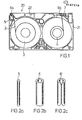
- the typical tape course in a conventional VHS video cassette 20 is shown in Fig. 1.
- the tape 2 is e.g. Coming from the coil 3 with its layer side over a cylindrical metal pin 5 (Fig. 2a), which is pressed into a corresponding recess of the cassette housing 21 made of plastic.
- the tape 2 is then deflected on the guide 6a, which is also fixed, and is guided along the cassette front 22 to the guide 6b.
- the guides 6a and 6b usually consist of seamless metallic hollow cylinders (Fig. 2b) or are bent from a sheet metal strip into a hollow cylinder (6 'in Fig. 2c) (according to DE-OS 28 17 316). From the guide 6b, the tape 2 is guided past the line roller 7 to the spool 4 and wound up there.
- tape guide devices 10a and 11a and 10b and 11b are shown, which correspond to the known guide elements 6a and 6b in the arrangement in the cassette 20.
- a guide element 10a or 10b according to the invention is shown in perspective on a larger scale in FIG.
- a guide belt 8 consists of foil material e.g. a metal foil and has, e.g. by bending, deformed bent or kinked outer edges 9a and 9b.
- the film is compressed from its extended position into an arcuate shape and placed over a post 10.
- the film compressed in the shape of drops or pears has a diameter which is somewhat smaller than the diameter of the post 10.
- the post 10 can be provided with an insertion bevel (not shown) for easier assembly of the bent metal foil 8 and, as a rule, slightly higher or lower (For example, about half as high) as the width of the metal foil 8.
- a holding element here designed as a slotted hollow cylinder 11, is provided in the immediate vicinity of the post 10.
- the slot 12 has a width that is at least somewhat larger than twice the thickness D of the guide belt 8.
- the slotted hollow cylinder 11 is selected to be approximately the same height as the post 10. As tests have shown, however, the guide band is still sufficiently secured in its position when the slotted hollow cylinder 11 is only approximately half the height of the post 10 .
- the guide band can also be inserted or clamped between the upper and lower parts (possibly the cassette housing).
- a safety pin 23 is shown, which tapers slightly conically and fastens to the cover part of the housing 21, e.g. molded, can be.
- the film 8 engages in the opening of the slotted hollow cylinder 11, if desired, so that it can also be fixed.
- Figure 5 shows a tape guide device as a replacement for the guide pin 5 (Fig. 1).
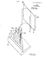
- the guide device according to the invention is formed by means of a pin 13 which is connected in one piece to the housing 21, the guide band 8 'is bent around this pin (a dashed intermediate form of the band is shown in FIG. 5A) and with its bent outer edges 9a', 9b 'between am Housing 21 attached holding elements, here between holding projections 14a and 14b, hung.
- the lower dimensioning limit given above for the slot 12 applies to the distance 12 'of the holding projections 14a and 14b from one another.
- Protrusions 14a and 14b can expediently be formed in one piece with lateral housing walls 24. Otherwise, the walls themselves or slots or grooves in inner wall parts of the housing 21 can also be used for the holding purpose.
- holding elements are separate clamping elements which clamp the ends of the guide band together.
- FIG. 6 A further advantageous form of the tape guide device according to the invention is shown in FIG. 6, in which the guide tape 8 ′′ consists of a central part 16, the length of which is selected to be slightly smaller than the circumference of the pin 13.
- the guide band 8 ′′ if necessary by spring action, automatically fits tightly on the largest part of the pin circumference and cannot slip, even if there is no further bend 17a / b of the guide band ends for hanging on the housing projections 14a / b.
- This version requires a resilient material, but this does not have to be the case with the other versions.
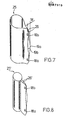
- Figures 7 and 8 show a further embodiment of the tape guiding device, which differs from the other embodiments in that the end portions 26, 26 'of the guide band 25, 25' are joined together prior to assembly, for example by spot welding or by Toggle d ere known connection methods, such as, for example, flanging the ends, etc.
- the end sections 26, 26 ' are connected at the top and bottom at the points 18a / b and the middle parts 19a and 19b of the end sections 26 are bent away from one another or away from their longitudinal axis, so that the bulge w is slightly larger than the width of the slot 12 of the slot hollow cylinder 11 or as the distance 12 'between the projections 14a and 14b.
- the tape guide according to the invention offers exceptionally great economic advantages.
- the material saving in comparison with a tape guide according to FIG. 2b alone is more than 80% when using a 30 ⁇ m metal foil and even more with a 20 ⁇ m foil.
- the invention also has advantages in terms of logistics and assembly, since the guide belt can be obtained as a tape wrap and can be processed particularly cheaply in an automatic production.
- the metal foils can also be subjected to a previous special surface treatment, plating, lapping, polishing, lubricating, etc. If special surface structures are required, these can be continuously impressed onto the metal foil in a simple manner.
- the tape guide according to the invention can also be produced using a plastic film.
- Suitable are e.g. Films made of high-strength and resistant plastics such as polyamideimide, polyetherimide, polysulfones, polyphenylene sulfide, etc.
- the thickness of the guide band is (first) at most about 150 ⁇ m or (second) at most 100 ⁇ m and is practically advantageously between about 10 and 50 ⁇ m or about 10 and 80 ⁇ m.
- Metal foils with 30 and 20 ⁇ m thickness have proven to be excellent, but other materials with other thicknesses can also be used.
- This thickness dimensioning ensures that microstructures based on rough machining on posts 10 or 13 are covered by the guide band and the surface can thereby easily obtain a high surface quality.
- the thickness can also be chosen so that macrostructures, e.g. a pattern on the post is molded outwards, e.g. to create a desired waviness of the guide surface.
- Special band guide cross-sectional contours i.e.
- shapes can also be roughly shaped with the shape of the post and can be refined or compensated for by attaching the guide band.
- the range from approx. 10 to approx. 80 ⁇ m of a metal foil, e.g. a spring steel foil, ensures in any case that there is sufficient flexibility of the guide belt in any case. With other materials, these areas can be somewhere else, but in any case below 150 ⁇ m.
- Base body and holding elements according to the present invention can be formed on one or more housing parts such as pins, pins, walls, etc., or be supported on them.
- FIGS. 9 to 12 A further embodiment of the guiding device is shown in FIGS. 9 to 12.
- FIG. 9 shows the metal foil strip 27 cut, punched and, for example, cut off at the ends 31, 32 once from the metal foil strip.
- the bending angle ⁇ is preferably chosen to be ⁇ 90 ° (less than 90 °) and> .45 0 (greater than 45 °) .
- the cylinder body shown as a support sleeve 29 in Fig. 10, consists of an economically producible, injection-molded plastic, e.g. Polystyrene. Appropriately on a surface line of the cylinder outer surface, two cutouts 33 are arranged as fastening slots and a radially projecting short pin 28.
- the metal foil strip 27 When mounting the metal foil strip 27 on the support sleeve 29, for example, as shown in FIG. 11, first the opening 30a is hooked onto the pin 29, the metal foil strip 27 is wrapped around the cylinder outer surface 34 of the support sleeve 29 and then at the other end also at the opening 36 Pin 28 suspended.
- the metal foil 27 has so much resilient flexibility at the bending or buckling edges 35 and 36 that this process is easy to carry out and that the metal foil 27 automatically catches after being hung on the pin 28 and can only be dismantled therefrom with tools.
- the tape guide device or metal foil guide preassembled in this way can then be stored in a magazine and fed to the cassette assembly device for automatic assembly. There it can then be plugged into the lower part of the cassette housing 37 shown in FIG. 12, for example on a hollow pin 39a.
- This hollow pin 39 has, for example on its foot on its side facing away from the belt path, a projection 40 which engages in a slot 33 of the support sleeve 29 and prevents it from rotating.
- a correspondingly shaped housing rib rests on the flattened surface 4 1 of the attached metal foil 27 or on the pin 28 of the support sleeve 29.
- the upper housing part 38 is placed with the upper hollow pin 39b and e.g. screwed with screws 42.
- the construction of the tape guide element according to the invention consisting of metal foil and a support body that can be separated from the tape transport device, has the advantage that significant changes to the tape transport device, in particular to a tape cassette, are not necessary.
- the pre-assembly on the support bodies, in particular the support sleeves, requires e.g. only minor modifications to the cassette housing, which can be easily retrofitted to existing tools.
- the assembly of the 'sleeves is possible with conventional machines.
- tape guide devices described also primarily reproduce or subsequently perfect fixed tape guide elements can, however, also movably arranged, for example pivotable or displaceable guides can thus be formed with the same advantages.
- Modifications to the base body e.g. Structures, rings, etc. are also possible, as are variants of similar suitable materials, in particular plastics, such as variants of foils with or without surface structures, different expansion coefficients, etc.
Landscapes
- Registering, Tensioning, Guiding Webs, And Rollers Therefor (AREA)
Abstract
Eine Bandführungsvorrichtung für Bandtransporteinrichtungen, insbesondere für Bandkassetten ist als Grundkörper (10) und darauf festgelegtem Führungsband (12), insbesondere aus Metallfolie, und wenigstens einem Halteelement (11) für die Endabschnitte des Führungsbandes ausgebildet. Das Führungsband (12) besitzt eine vorgegebene Dicke und gegebenenfalls in Betriebslage eine Tropfen- oder Birnenform. die Bandführungsvorrichtung kann auch als zumindest teilweise an der Oberfläche zylindrischer Grundkörper und darübergespannte oder andersartig befestigte Metallfolie ausgebildet sein. Als Trennbare sowie vormontierbare Einheit ist die Vorrichtung damit auch für die automatische Fertigung einsetzbar. Einsetzbar ist die Führungsvorrichtung sowohl für feststehende als auch für in Grenzen bewegliche Bandführungen, auf dem Gebiet der bandförmigen Aufzeichnungsträger wie Filme, Magnetbänder, Lochstreifen usw.A tape guide device for tape transport devices, in particular for tape cassettes, is designed as a base body (10) and a guide tape (12) fixed thereon, in particular made of metal foil, and at least one holding element (11) for the end sections of the guide tape. The guide band (12) has a predetermined thickness and, if necessary, a drop or pear shape in the operating position. the tape guiding device can also be designed as an at least partially cylindrical surface on the surface and metal foil stretched over or attached in some other way. As a separable and preassembled unit, the device can thus also be used for automatic production. The guide device can be used both for stationary and for tape guides that can be moved within limits, in the field of tape-shaped recording media such as films, magnetic tapes, punched tapes, etc.
Description
Die Erfindung betrifft eine Bandführungsvorrichtung für Bandtransporteinrichtungen, insbesondere Magnetbandeinrichtungen, und Magnetbandkassetten damit, bestehend aus einem ruhend auf einem wenigstens teilweise formstabilen Grundkörper mit definierter Oberfläche angeordneten flexiblen Führungsband, das die Führungsfläche für das Magnetband bildet.The invention relates to a tape guide device for tape transport devices, in particular magnetic tape devices, and magnetic tape cassettes, consisting of a flexible guide tape which rests on an at least partially dimensionally stable base body with a defined surface and forms the guide surface for the magnetic tape.
Es sind Bandführungen, insbesondere feststehende Führungen, für dünne, flexible, glatte, streifenförmige Bänder, insbesondere Magnetbänder in Kassetten und/oder Geräten zum Halten bzw. zur reibungsarmen und beschädigungsfreien Führung der Bänder während aller Bewegungsvorgänge. z.B. beim Umspulen, bei Aufnahme- bzw. Abspielvorgängen, des Bandes bekannt.They are tape guides, in particular fixed guides, for thin, flexible, smooth, strip-shaped tapes, in particular magnetic tapes in cassettes and / or devices for holding or for low-friction and damage-free guiding of the tapes during all movement processes. e.g. when rewinding, during recording or playback operations, the tape is known.
Für solche Bänder sind eine Vielzahl verschiedener Führungselemente bekannt, die alle die Aufgabe haben, das Band in Ruhestellung und/oder im . Bewegungszustand in einer bestimmten Lage, Form oder Bahn zu halten und/oder zu führen, so daß an, oder mit dem Band die gewünschten Maßnahmen ddurchgeführt werden können. Wo immer es geht, benutzt der Fachmann dazu drehbar gelagerte zylindrische Rollen, die bei sachgerechter Ausführung eine nahezu reibungslose, verschleißfreie und energiesparende Bandbewegung erlauben. In vielen Fällen, so z.B. für in großen Mengen hergestellte kompakte Magnetbandkassetten und/oder -geräte, müssen aus Gründen des Bandgleichlaufs und/oder aus Platz- und Kostengründen usw., feststehende Bandführungen mit relativ kleinen Durchmessern verwendet werden.For such tapes a variety of different guide elements are known, all of which have the task of the tape in the rest position and / or in. To maintain and / or guide the state of motion in a certain position, shape or path, so that the desired measures can be carried out on or with the belt. Wherever possible, the specialist uses rotatably mounted cylindrical rollers that, when properly designed, allow for an almost smooth, wear-free and energy-saving belt movement. In many cases, e.g. for compact magnetic tape cassettes and / or devices produced in large quantities, fixed tape guides with relatively small diameters must be used for reasons of tape synchronization and / or for reasons of space and cost, etc.
Für VHS-Videokassetten sind mit der DE-OS 28 17 318 Bandführungen bekannt geworden, die aus metallischen Hohlzylinderkörpern bestehen, die aus einem Metallblechstreifen gebogen sind und mit mindestens einem Einschnitt zum Eingriff eines Verdrehfortsatzes des Kassettengehäuses ausgebildet sind. Die Herstellung dieses Hohlzylinders aus dem Blechstreifen bietet keine wesentlichen Vorteile funktioneller oder wirtschaftlicher Art. Eine mögliche Teilbearbeitung der Oberfläche der Hohlzylinderkörper ist ebenfalls nicht ratsam, da bei kleinen Durchmessern der Führungselemente mit bekannten Bearbeitungsmaschinen (z.B. Geräten zum spitzenlosen Schleifen) eine Zylinderfläche leichter und schneller zu bearbeiten ist, als nur ein Teil davon.For VHS video cassettes, tape guides have become known from DE-OS 28 17 318, which consist of metallic hollow cylindrical bodies which are bent from a sheet metal strip and which are designed with at least one incision for engaging an extension of the cassette housing. The production of this hollow cylinder from the sheet metal strip does not offer any significant functional or economic advantages. Possible partial machining of the surface of the hollow cylinder body is also not advisable, since with small diameter guide elements with known processing machines (e.g. devices for centerless grinding) a cylinder surface can be closed more easily and quickly edit is as part of it.
Mit der DE-AS 24 31 969 ist eine Bandkassette mit einem festen Befestigungsstift und einer Hülse bekannt, wobei die Hülse eine konkave Oberfläche besitzt und elastisch ausgebildet ist, daß sie bezüglich ihrer normalen Gestalt deformiert aufsteckbar ist und mittels Reibsitzes und Federwirkung am Stift festgehalten wird. Die Herstellung dieser Hülse bereitet wegen ihrer konkaven Oberfläche und ihrer geschlossenen Ringform einige Schwierigkeiten. Zur lagerichtigen Anbringung bzw. Befestigung erfordert diese bekannte Hülse einen zusätzlichen Endflansch als Bezugsfläche.With DE-AS 24 31 969 a tape cassette with a fixed fastening pin and a sleeve is known, the sleeve having a concave surface and being designed to be elastic so that it can be plugged in deformed with respect to its normal shape and by means of a friction seat and Spring action is held on the pin. The manufacture of this sleeve presents some difficulties due to its concave surface and its closed ring shape. For correct installation or attachment, this known sleeve requires an additional end flange as a reference surface.
Es ist mit der DE-PS 2 535 276 eine großflächige Bandführung bekannt, die aus einem festen Grundkörper und einem daran befestigten federelastischen und im Hook'schen Bereich verformten und unter Zugspannung befestigten Metallstreifen besteht. Die Befestigung unter Zugspannung erfolgt dabei, um eine konkave Führungsfläche für das Magnetband auszubilden. Bei dieser Bandführung soll ebenfalls eine gewölbte Führungsfläche ausgebildet werden unter Verwendung eines ausreichend dünnen Streifenmaterials, "wozu die Oberfläche des Grundkörpers geeignet geformt sein muß, damit sich der Streifen in gewünschter Weise in gespannter Lage daran anschmiegt". Praktisch besteht dieser Streifen aus V2A-Stahl und besitzt eine Dicke im Bereich von. 0,4 mm (400µm).It is known from DE-PS 2 535 276 a large-area tape guide, which consists of a solid base body and a spring-elastic and attached to it deformed in Hook's area and fastened under tensile stress metal strips. The attachment under tensile stress takes place in order to form a concave guide surface for the magnetic tape. With this tape guide, a curved guide surface is also to be formed using a sufficiently thin strip material "for which the surface of the base body must be suitably shaped so that the strip conforms to it in the desired manner in a tensioned position". Practically, this strip is made of V2A steel and has a thickness in the range of. 0.4 mm (400 µm).
Es ist Aufgabe der vorliegenden Erfindung, eine Bandführungsvorrichtung bereitzustellen, die trotz zu erfüllender hoher Anforderungen an'Verschleißfestigkeit und Oberflächenfeinstruktur wesentlich wirtschaftlicher herstellbar und leichter montierbar ist. Die Erfindung soll auch Bandkassetten mit derartigen Bandführungsvorrichtungen bereitstellen.It is an object of the present invention to provide a belt guiding device which, despite the high demands on wear resistance and fine surface structure to be met, is much more economical to manufacture and easier to assemble. The invention is also intended to provide tape cassettes with such tape guide devices.
Die Aufgabe wird erfindungsgemäß mit einer Bandführungsvorrichtung bzw. einer Bandkassette der eingangs definierten Art dadurch gelöst, daß das Führungsband eine größere Länge besitzt als die Länge der Umfangskontur des Grundkörpers beträgt und die Dicke des Führungsbandes höchstens etwa 150µm beträgt, so daß die Form der Führungsfläche ausschließlich durch die Form und/oder die Form der Oberfläche des Grundkörpers bestimmt ist, und daß mindestens ein formstabiles Halteelement vorgesehen ist zur verdrehsicheren Halterung der überstehenden Endabschnitte des Führungsbandes.The object is achieved with a tape guide device or a tape cassette of the type defined in the introduction that the guide tape has a greater length than the length of the circumferential contour of the base body and the thickness of the guide tape is at most about 150 microns, so that the shape of the guide surface exclusively is determined by the shape and / or the shape of the surface of the base body, and that at least one dimensionally stable holding element is provided for the torsion-proof mounting of the projecting end sections of the guide band.
Damit sind die an die Bandführungen, insbesondere in Bandkassetten, zu stellenden Anforderungen einfach erfüllbar und niedrige Reibung, geringer Bandverschleiß. niedrige Fehlerraten und ungestörter Bandlauf auch bei extrem langen Standzeiten werden erreicht. Insbesondere ist es möglich, sehr ebene Führungsflächen mit eingestellter Rauhigkeit auszubilden, ohne daß dazu extremer Bearbeitungsaufwand notwendig wäre.This means that the requirements placed on the tape guides, particularly in tape cassettes, can be easily met and low friction, low tape wear. Low error rates and undisturbed belt run are achieved even with extremely long downtimes. In particular, it is possible to form very flat guide surfaces with a set roughness without the need for extreme machining.
Zweckmäßig ist eine Dicke des Führungsbandes im Bereich zwischen etwa 10µm und 50µm. Aus Befestigungsgründen kann das Führungsband aus einem federelastischen Material bestehen.A thickness of the guide band in the range between approximately 10 μm and 50 μm is expedient. For reasons of fastening, the guide band can consist of a resilient material.
Praktisch kann das Führungsband mittels Klemmung am Grundkörper und/oder am Halteelement gehalten sein.In practice, the guide band can be held on the base body and / or on the holding element by means of clamping.
Der Grundkörper ist zweckmäßig wenigstens teilweise mit zylindrischer Oberfläche ausgebildet.The base body is expediently at least partially designed with a cylindrical surface.
Das Halteelement kann einfach mit Schlitz oder Nut, insbesondere als geschlitzter Zylinderkörper, zur Aufnahme der Endabschnitte des Führungsbandes ausgebildet sein. Es ist auch möglich, zwei mit Abstand nebeneinander angeordnete Haltevorsprünge zu verwenden. Falls die Bandtransporteinrichtung eine 8andkassette ist, kann das Halteelement wenigstens teilweise aus einer Gehäusewand bestehen. Die Halteelemente in der Kassette sind zweckmäßig im Spritzguß am Kassettengehäuse hergestellt.The holding element can simply be designed with a slot or groove, in particular as a slotted cylinder body, for receiving the end sections of the guide band. It is also possible to use two holding projections arranged next to one another at a distance. If the tape transport device is a tape cassette, the holding element can at least partially consist of a housing wall. The holding elements in the cassette are expediently injection molded onto the cassette housing.
In weiterer Ausführung können die Endabschnitte des Führungsbandes miteinander verbunden sein, wodurch nach Herstellen ein einfaches Einsetzen in das oder die Halteelemente möglich ist. Dabei kann die Verbindung der Endabschnitte auch derart erfolgen, daß eine Wölbung jedes Endabschnittes von der Längsachse fort erfolgt, was ein Einklemmen am Halteelement erleichtert. Vorteilhaft ist ein Führungsband mit einer Omega-Querschnittsform, eine Tropfen- oder Birnenform in eingesetzter Lage ist jedoch ebenfalls günstig.In a further embodiment, the end sections of the guide band can be connected to one another, which, after manufacture, enables simple insertion into the holding element or elements. The end sections can also be connected in such a way that each end section is curved away from the longitudinal axis, which makes it easier to clamp them on the holding element. A guide band with an omega cross-sectional shape is advantageous, but a drop or pear shape in the inserted position is also favorable.
In weiterer Ausbildung sind die Endabschnitte des Führungsbandes mit Befestigungsöffnungen versehen, wodurch es einfach ist, das Führungsband am Zylinderkörper zu befestigen.In a further embodiment, the end sections of the guide band are provided with fastening openings, which makes it easy to fasten the guide band to the cylinder body.
Praktisch ist der Zylinderkörper mit Befestigungsschlitz ausgebildet. womit gleichzeitig eine Verdrehsicherung realisierbar ist.In practice, the cylinder body is designed with a fastening slot. which can also be used to prevent rotation.
Im weiteren ist der Zylinderkörper als separates Teil hergestellt und besteht insbesondere aus Polystyrol. Damit ist der als Massenteil fertigbare Zylinderkörper sehr wirtschaftlich herstellbar.Furthermore, the cylinder body is made as a separate part and consists in particular of polystyrene. The cylinder body, which can be manufactured as a mass part, can thus be produced very economically.
Praktisch ist ein radial und axial mittig angeordneter Zapfen als Halteelement am Zylinderkörper vorgesehen.In practice, a radially and axially central pin is provided as a holding element on the cylinder body.
Zweckmäßig können Zylinderkörper und Führungsband als vormontierbare Einheit ausgebildet, die Befestigungseinrichtungen umfassen.The cylinder body and guide band can expediently be designed as a preassembled unit, which comprise fastening devices.
Die oben beschriebenen Führungsvorrichtungen sind auch in Verbindung mit Bandkassetten Gegenstand der Erfindung.The guide devices described above are also the subject of the invention in connection with tape cassettes.
Ausführungsbeispiele der Erfindung sind in der Zeichnung dargestellt und nachfolgend beschrieben.Embodiments of the invention are shown in the drawing and described below.
In der Zeichnung zeigen
- Figur 1 eine schematische Videokassette
- Figur 2a bis 2c Bandführungselemente
Figur 3 eine neue Variante von Bandführungselementen- Figuren 4A bis 4C ein Führungsband, ein Sicherungsteil und ein fertigmontiertes Führungselement
- Figuren 5A und 5B eine zweite Ausführung einer Führungsvorrichtung
- Figuren 6A und 6B eine dritte Ausführung einer Führungsvorrichtung
Figuren 7 und 8 Ausführungen eines Führungsbandes mit verbundenen Endabschnitten- Figur 9 ein Führungsband
Figur 10 einen HohlzylinderkörperFigur 11 ein vormontiertes FührungselementFigur 12 ein fertig eingesetztes und befestigtes Führungselement in einer Bandtransporteinrichtung, insbesondere einer Bandkassette
- Figure 1 is a schematic video cassette
- Figure 2a to 2c tape guide elements
- Figure 3 shows a new variant of tape guide elements
- Figures 4A to 4C, a guide belt, a securing part and a fully assembled guide element
- Figures 5A and 5B, a second embodiment of a guide device
- Figures 6A and 6B, a third embodiment of a guide device
- Figures 7 and 8 versions of a guide belt with connected end portions
- Figure 9 is a guide belt
- Figure 10 shows a hollow cylinder body
- Figure 11 shows a pre-assembled guide element
- Figure 12 shows a fully inserted and fastened guide element in a tape transport device, in particular a tape cassette
Den typischen Bandverlauf in einer herkömmlichen VHS-Videokassette 20 zeigt Fig. 1. Das Band 2 wird z.B. von der Spule 3 kommend mit seiner Schichtseite über einen zylindrischen Metallstift 5 (Fig. 2a) geführt, der in eine entsprecbende Vertiefung des aus Kunststoff gefertigten Kassettengehäuses 21 eingepreßt ist. Danach wird das Band 2 an der ebenfalls feststehenden Führung 6a umgelenkt und längs der Kassettenfront 22 bis zur Führung 6b geführt. Die Führungen 6a und 6b bestehen üblicherweise aus nahtlosen metallischen Hohlzylindern (Fig. 2b) oder sind aus einem Metallblechstreifen zu einem Hohlzylinder (6' in Fig. 2c) gebogen (gemäß DE-OS 28 17 316). Von der Führung 6b wird das Band 2 an der Linienrolle 7 vorbei zur Spule 4 geführt und dort aufgewickelt.The typical tape course in a conventional
Die Erfahrung hat nun gezeigt, daß an die Oberfläche der feststehenden Führungen 5, 6a und 6b hohe Anforderungen zu stellen sind, da es sonst zu zu hoher Reibung, zu Bandverschluß. Fehleranstieg und in Extremfällen zum Bandstillstand kommen kann. Diese Anforderungen betreffen vor allem die Verschleißfestigkeit, die Ebenheit, die Oberflächenfeinstruktur und deren Rauhigkeit. Andererseits müssen die Führungen auch gegen Korrosion geschützt sein. Alle Forderungen zusammen sind nur durch die Verwendung von teurem, korrosionsfreiem Material, z.B. rostfreiem Stahl, Keramik (DE-OS 32 18 097) oder plattiertem Material (z.B. DE-OS 31 00 453 und DE-AS 28 40 069) und mit aufwendigen Vor- und Nachbearbeitungen, z.B. Überdrehen, Schleifen, Läppen und Polieren, zu erfüllen.Experience has now shown that high demands are to be placed on the surface of the fixed guides 5, 6a and 6b, since otherwise there would be excessive friction and tape closure. Increase in errors and, in extreme cases, the line can come to a standstill. Above all, these requirements relate to wear resistance, flatness, surface fine structure and their roughness. On the other hand, the guides must also be protected against corrosion. All requirements can only be met through the use of expensive, corrosion-free material, e.g. stainless steel, ceramics (
Andererseits sind Führungselemente mit Streifen aus Kunststoff mit reibungsvermindernden Zusätzen wie Graphit usw. (z.B. DE-OS 27 22 509) bzw. mit oberflächenaktiven Zusätzen (OE-OS 32 01 444) bekannt geworden, mit denen sich auch bei Spritzgußherstellung die gewünschten Oberflächencharakteristiken erreichen lassen. Versuche haben jedoch gezeigt, daß sich mit solchen Führungen in gängigen Videokassetten nur relativ kurzzeitig ein störungsfreier Bandbetrieb erreichen läBt, da der Kunststoff durch das Band nach wenigen Betriebsstunden so stark ausgewaschen und/oder geglättet wird, daß die Reibung wieder ansteigt, was bis zum Stillstand der Bänder infolge Adhäsion fuhren kann.On the other hand, guide elements with strips of plastic with friction-reducing additives such as graphite etc. (for
Die Nachteile der bekannten Bandführungen werden mit Bandführungen gemäß vorliegender Erfindung vermieden, die im folgenden beschrieben sind.The disadvantages of the known tape guides are avoided with tape guides according to the present invention, which are described below.
In Figur 3 sind Bandführungsvorrichtungen 10a und 11a sowie 10b und 11b dargestellt, die den bekannten Führungselementen 6a und 6b in der Anordnung in der Kassette 20 entsprechen.In Figure 3,
In Figur 4 ist ein erfindungsgemäßes Führungselement 10a oder 10b in größerem Maßstab perspektivisch dargestellt.A
Ein Führungsband 8 besteht aus Folienmaterial z.B. einer Metallfolie und besitzt, z.B. durch Biegen, verformte abgebogene oder abgeknickte Außenkanten 9a und 9b. Die Folie wird aus ihrer gestreckten Lage in eine bogenförmige Form zusammengedrückt und über einen Pfosten 10 gestülpt. Dabei hat die in Tropfen- oder Birnenform zusammengedrückte Folie einen Durchmesser, der etwas kleiner ist, als der Durchmesser des Pfostens 10. Der Pfosten 10 kann zur erleichterten Montage der gebogenen Metallfolie 8 mit einer nicht dargestellten Einführschräge versehen und im Regelfall geringfügig höher oder auch niedriger (z.B. etwa halb so hoch) ausgebildet sein als die Breite der Metallfolie 8. In unmittelbarer Nähe des Pfostens 10 ist ein Halteelement, hier als geschlitzter Hohlzylinder 11 ausgebildet, vorgesehen. Der Schlitz 12 besitzt dabei eine Breite, die mindestens etwas größer ist als die doppelte Dicke,D des Führungsbandes 8.A
Die abgebogenen Außenkanten 9a/b greifen in den Schlitz-Hohlzylinder 11 ein und stützen sich daran ab und verhaken sich an den Innenseiten des Schlitzes 12. Selbst bei sehr geringer Federwirkung des Führungsbandes 8 legt sich dieses an den Pfosten 10 an, wobei eventuell unbeabsichtigte. spritztechnisch bedingte Unebenheiten der Pfostenoberfläche überdeckt und somit kompensiert werden. Darin liegt einer der Vorteile der erfindungsgemäßen 8andführungsvorrichtung, da dadurch auf eine aufwendige Bearbeitung des Pfostens 10 zur Erzeugung einer hochgenauen Bandführungsfläche verzichtet werden kann.The bent
Normalerweise wird der Schlitz-Hohlzylinder 11 etwa gleich hoch gewählt wie der Pfosten 10. Wie Versuche gezeigt haben, ist das Führungsband jedoch auch dann noch ausreichend in seiner Lage gesichert, wenn der Schlitz-Hohlzylinder 11 nur etwa halb so hoch wie der Pfosten 10 ist. Das Führungsband kann auch zwischen Ober- und Unterteilen (gegebenenfalls des Kassettengehäuses) eingesteckt oder eingeklemmt sein.Normally, the slotted
In Figur 4B ist ein Sicherheitszapfen 23 dargestellt, der leicht konisch zuläuft und am Deckelteil des Gehäuses 21 befestigt, z.B. angeformt, sein kann. In die Öffnung des Schlitz-Hohlzylinders 11 eingreifend ist die Folie 8, wenn gewünscht, damit zusätzlich festlegbar.In Figure 4B a
Figur 5 zeigt eine Bandführungsvorrichtung als Ersatz für den Führungsstift 5 (Fig. 1). Auch hier wird die erfindungsgemäße Führungsvorrichtung mittels eines einstückig mit dem Gehäuse 21 verbundenen Stiftes 13 ausgebildet, das Führungsband 8' um diesen Stift herumgebogen (eine gestrichelt dargestellte Zwischenform des Bandes zeigt Fig: 5A) und mit seinen abgebogenen Außenkanten 9a', 9b' zwischen am Gehäuse 21 angebrachten Halteelementen, hier zwischen Haltevorsprüngen 14a und 14b, eingehängt. Für den Abstand 12' der Haltevorsprünge 14a und 14b voneinander gilt die oben für den Schlitz 12 gegebene untere Dimensionierungsgrenze. Vorsprünge 14a und 14b können zweckmäßig mit seitlichen Gehäusewänden 24 einstückig ausgebildet sein. Andernfalls können auch die Wände selbst oder Schlitze oder Nuten in Innenwandteilen des Gehäuses 21 für den Haltezweck verwendet werden.Figure 5 shows a tape guide device as a replacement for the guide pin 5 (Fig. 1). Here too, the guide device according to the invention is formed by means of a
Es ist auch möglich, Halteelemente als separate Klemmelemente auszubilden, die die Enden des Führungsbandes zusammenklemmen.It is also possible to design holding elements as separate clamping elements which clamp the ends of the guide band together.
Eine weitere günstige Form der erfindungsgemäßen Bandführungsvorrichtung zeigt Figur 6, in der das Führungsband 8'' aus einem Mittelteil 16 besteht, dessen Länge geringfügig kleiner gewählt ist als der Umfang des Stiftes 13. Die gegenüber dem Führungsband B' verlängerten abgebogenen Kanten 15a und 15b werden wiederum an den Vorsprüngen 14a und 14b abgestützt. So gestaltet legt sich das Führungsband 8'', gegebenenfalls durch Federwirkung, selbstätig eng am größten Teil des Stiftumfanges an und kann nicht verrutschen, auch wenn auf eine weitere Abkantung 17a/b der Führungsbandenden zum Einhängen an den Gehäusevorsprüngen 14a/b verzichtet wird. Diese Ausführung setzt ein federelastisches Material voraus, was jedoch nicht bei den anderen Ausführungen der Fall sein muß.A further advantageous form of the tape guide device according to the invention is shown in FIG. 6, in which the
Figuren 7 und 8 zeigen eine weitere Ausbildung der Bandführungsvorrichtung, die sich von den anderen Ausgestaltungen dadurch unterscheidet, daß die Endabschnitte 26, 26' des Führungsbandes 25, 25' vor der Montage miteinander verbunden werden, z.B. durch Punktschweißen oder auch durch an- dere bekannte Verbindungsmethoden, wie z.B. Umbördeln der Enden usw.. In vorteilhafter Form werden die Endabschnitte 26. 26' oben und unten an den Stellen 18a/b verbunden und die Mittelteile 19a und 19b der Endabschnitte 26 voneinanderfort bzw. von ihrer Längsachse fort gebogen, so daß die Auswölbung w geringfügig größer ist als die Breite des Schlitzes 12 des Schlitz-Hohlzylinders 11 bzw. als der Abstand 12' zwischen den Vorsprüngen 14a und 14b.Figures 7 and 8 show a further embodiment of the tape guiding device, which differs from the other embodiments in that the
In den Ausbildungen der miteinander verbundenen Endabschnitte 26 oder 26' ist eine Verbindung mit dem oder eine Festlegung am Gehäuse 21 über Schlitze oder Nuten in vielerlei Form möglich. Eventuell können auch Einschnitte in Boden- und/oder Deckelteilen des Gehäuses 21 dafür ausreichen.In the designs of the
Praktisch bietet die erfindungsgemäße Bandführung ausnehmend große wirtschaftliche Vorteile. So beträgt allein die Materialeinsparung im Vergleich mit einer Bandführung gemäß Figur 2b mehr als 80 X, bei Verwendung einer 30µm starken Metallfolie, und noch mehr bei einer 20µm Folie. Darüber hinaus bringt die Erfindung auch Vorteile bei der Logistik und Montage, da das Führungsband als Bandwickel bezogen und besonders günstig in einer automatischen Fertigung verarbeitet werden kann.In practice, the tape guide according to the invention offers exceptionally great economic advantages. The material saving in comparison with a tape guide according to FIG. 2b alone is more than 80% when using a 30 μm metal foil and even more with a 20 μm foil. In addition, the invention also has advantages in terms of logistics and assembly, since the guide belt can be obtained as a tape wrap and can be processed particularly cheaply in an automatic production.
Als Material wird vorteilhaft handelsüblicher, gezogener bzw. gewalzter hochlegierter, federharter unmagnetischer Edelstahl mit einer Zugfestigkeit von ca. 500 bis 1200 N/m mit einer Oberflächenrauhigkeit von Rz < 2pm, vorzugsweise < 1µm, verwandt. Eine solche Metallfolie wird zweckmäßig so verwendet, daß Walz- oder Ziehrichtung parallel zur Magnetbandlaufrichtung liegt. Oberflächengezogene und/oder -gewalzte Folien sind besonders günstig, weil sie unter anderem keine spitzen oder scharfen Oberflächenstrukturen aufweisen, was einem schonenden Bandlauf sehr entgegen kommt. Selbstverständlich ist auch die Verwendung anderer Metallfolien möglich. Bei besonders hohen Anforderungen oder bei Verwendung billigeren Materials können die Metallfolien auch einer vorherigen speziellen Oberflächenbehandlung, Plattieren, Läppen, Polieren, Lubrizieren usw. unterzogen werden. Werden spezielle Oberflächenstrukturen gewünscht, so lassen sich diese in einfacher Weise der Metallfolie fortlaufend aufprägen.Commercial, drawn or rolled high-alloy, spring-hard non-magnetic stainless steel with a tensile strength of approximately 500 to 1200 N / m with a surface roughness of R z <2 pm, preferably <1 μm, is advantageously used as the material. Such a metal foil is expediently used so that the rolling or drawing direction is parallel to the direction of the magnetic tape. Surface drawn and / or rolled foils are particularly cheap because, among other things, they do not have any pointed or sharp surface structures, which is very beneficial for a gentle belt run. Of course, the use of other metal foils is also possible. If the requirements are particularly high or if cheaper materials are used, the metal foils can also be subjected to a previous special surface treatment, plating, lapping, polishing, lubricating, etc. If special surface structures are required, these can be continuously impressed onto the metal foil in a simple manner.
Selbstverständlich ist die erfindungsgemäße Bandführung auch unter Verwendung einer Kunststoff-Folie herzustellen. Geeignet sind z.B. Folien aus hochfesten und widerstandsfähigen Kunststoffen wie Polyamidimid, Polyetherimid, Polysulfone, Polyphenylensulfid usw..Of course, the tape guide according to the invention can also be produced using a plastic film. Suitable are e.g. Films made of high-strength and resistant plastics such as polyamideimide, polyetherimide, polysulfones, polyphenylene sulfide, etc.
Die Dicke des Führungsbandes beträgt (erstens) höchstens etwa 150µm oder (zweitens) höchstens 100µm und liegt praktisch vorteilhaft etwa zwischen ca. 10 und 50µm oder ca. 10 und 80µm. Metallfolien mit 30 und 20µm Dicke haben sich hervorragend bewährt, es sind jedoch auch andere Materialien mit anderen Dicken benutzbar. Diese Dickendimensionierung stellt sicher, daß auf Grobbearbeitung beruhende Mikrostrukturen am Pfosten 10 oder 13 durch das Führungsband überdeckt werden und dadurch die Oberfläche auf einfachem Wege eine hohe Oberflächengüte erhalten kann. Die Dicke kann auch so gewählt werden, daß Makrostrukturen, z.B. ein Muster auf dem Pfosten, nach außen durchgeformt wird, z.B. um eine gewollte Welligkeit der Führungsfläche herzustellen. Ebenfalls können spezielle Bandführungsquerschnittskonturen (also Formen) mit der Formgebung des Pfostens grob ausgebildet werden und durch Anbringung des Führungsbandes verfeinert oder ausgeglichen werden. Der Bereich von ca. 10 bis ca. 80µm einer Metallfolie, z.B. einer Federstahlfolie, stellt jedenfalls sicher, daß auf jeden Fall eine ausreichende Flexibilität des Führungsbandes gegeben ist. Bei anderen Materialien können diese Bereiche woanders, aber jedenfalls unterhalb von 150µm, liegen.The thickness of the guide band is (first) at most about 150 µm or (second) at most 100 µm and is practically advantageously between about 10 and 50 µm or about 10 and 80 µm. Metal foils with 30 and 20µm thickness have proven to be excellent, but other materials with other thicknesses can also be used. This thickness dimensioning ensures that microstructures based on rough machining on
Grundkörper und Halteelemente gemäß vorliegender Erfindung können an einem oder mehreren Gehäuseteilen wie Zapfen, Stiften, Wandungen usw. ausgebildet sein, bzw. sich daran abstützen.Base body and holding elements according to the present invention can be formed on one or more housing parts such as pins, pins, walls, etc., or be supported on them.
Eine weitere Ausführung der Führungsvorrichtung zeigen die Figuren 9 bis 12.A further embodiment of the guiding device is shown in FIGS. 9 to 12.
Figur 9 zeigt den z.B. vom Metallfolien-Band abgeschnittenen, gestanzten und an den Enden 31, 32 jeweils einmal umgebogenen Metallfolienstreifen 27. Der Abbiegungswinkel a ist dabei vorzugsweise < 90° (kleiner 90°) und >.450 (größer 45°) gewählt. Vorzugsweise befinden sich in der Mitte der Enden 31 und 32 Ausnehmungen der Löcher 30.FIG. 9 shows the
Der Zylinderkörper, als Stützhülse 29 in Fig. 10 gezeigt, besteht aus einem wirtschaftlich herstellbaren, spritztechnisch leicht verarbeitbaren Kunststoff, z.B. Polystyrol. Zweckmäßig auf einer Mantellinie der Zylinderaußenflache sind zwei Ausschnitte 33 als Befestigungsschlitze und ein radial vorspringender kurzer Zapfen 28 angeordnet.The cylinder body, shown as a
Bei der Montage des Metallfolienstreifens 27 auf der Stützhülse 29 wird beispielsweise, wie in Figur 11 dargestellt, zuerst die Öffnung 30a am Zapfen 29 eingehängt, der Metallfolienstreifen 27 um die Zylinderaußenfläche 34 der Stützhülse 29 herumgewickelt und dann am anderen Ende an der Öffnung 36 ebenfalls am Zapfen 28 eingehängt. Die Metallfolie 27 hat an den Biege- oder Knickkanten 35 und 36 soviel federnde Flexibilität, daß dieser Vorgang leicht auszuführen ist und daß sich die Metallfolie 27 nach dem Einhängen am Zapfen 28 selbsttätig unverlierbar verhakt und nur noch mit Werkzeugen davon zu demontieren ist.When mounting the
Die so vormontierte Bandführungsvorrichtung oder Metallfolienführung kann dann magaziniert und der Kassettenmontagevorrichtung zur automatischen Montage zugeführt werden. Dort kann sie dann in das in Fig. 12 ausschnittsweise dargestellte Kassettengehäuseunterteil 37 z.B. auf einen Hohlzapfen 39a aufgesteckt werden. Dieser Hohlzapfen 39 besitzt beispielsweise an seinem Fuß an seiner dem Bandweg abgewandten Seite einen Vorsprung 40, der in einen Schlitz 33 der Stützhülse 29 eingreift und diese an einer Verdrehung hindert. Selbstverständlich gibt es auch andere Möglichkeiten der Verdrehsicherung. z.B. dadurch, daß eine entsprechend geformte Gehäuserippe (nicht dargestellt) an der abgeplatteten Fläche 41 der befestigten Metallfolie 27 oder am Zapfen 28 der Stützhülse 29 anliegt.The tape guide device or metal foil guide preassembled in this way can then be stored in a magazine and fed to the cassette assembly device for automatic assembly. There it can then be plugged into the lower part of the
Nach der Montage der Metallfolienführung im Gehäuseunterteil 12 wird das Gehäuseoberteil 38 mit dem oberen Hohlzapfen 39b aufgesetzt und z.B. mit Schrauben 42 verschraubt.After the assembly of the metal foil guide in the
Es ist praktisch ebenso möglich, die Stützhülse 29 mit der Folie 27, in eine Kreisnut im Gehäuseunterteil 37 einzusetzen, die gegebenenfalls auch im Oberteil 38 vorhanden sein kann. Selbstverständlich ist auch in diesen Fällen die Hülse 29 durch Schrauben in der Praxis festlegbar.It is practically also possible to insert the
Der Aufbau des erfindungsgemäßen Bandführungselements, bestehend aus Metallfolie und von der Bandtransporteinrichtung trennbarem Stützkörper, hat den Vorteil, daß wesentliche Änderungen an der Bandtransporteinrichtung, insbesondere an einer Bandkassette, nicht notwendig sind. Die Vormontage auf den Stützkörpern, insbesondere den Stützhülsen, erfordert z.B. nur geringfügige Modifikationen am Kassettengehäuse, die leicht nachträglich an vorhandenen Werkzeugen vornehmbar sind. Die Montage der ' Hülsen ist mit üblichen Automaten möglich.The construction of the tape guide element according to the invention, consisting of metal foil and a support body that can be separated from the tape transport device, has the advantage that significant changes to the tape transport device, in particular to a tape cassette, are not necessary. The pre-assembly on the support bodies, in particular the support sleeves, requires e.g. only minor modifications to the cassette housing, which can be easily retrofitted to existing tools. The assembly of the 'sleeves is possible with conventional machines.
Wenn beschriebene Bandführungsvorrichtungen auch in erster Linie feststehende Bandführungselemente nachbilden bzw. nachträglich vervollkommnen können, so sind jedoch auch beweglich angeordnete, z.B. schwenkbare oder verschiebbare Führungen damit mit denselben Vorteilen ausbildbar.If tape guide devices described also primarily reproduce or subsequently perfect fixed tape guide elements can, however, also movably arranged, for example pivotable or displaceable guides can thus be formed with the same advantages.
Es sind im Rahmen des Fachwissens liegende Weiterbildungen, die besondere Befestigungsarten, Oberflächenstrukturen, Klemmverbindungen, Kombinationen mehrerer Führungselemente durch ein oder mehrere gemeinsame Führungsbänder usw. denkbar, und auch dafür wird Schutz im Rahmen der Schutzansprüche begehrt.There are further developments within the scope of specialist knowledge, the special types of fastening, surface structures, clamp connections, combinations of several guide elements by one or more common guide bands, etc., and protection for this is also sought within the scope of the protection claims.
Im Rahmen der vorliegenden Erfindung sind außerdem Modifikationen am Grundkörper, z.B. Strukturen, Ringe usw. ebenso möglich wie Varianten von ähnlichen geeigneten Materialien, insbesondere Kunststoffen, wie Varianten von Folien mit oder ohne Oberflächenstrukturen, unterschiedlichen Dehnungskoeffizienten usw..Modifications to the base body, e.g. Structures, rings, etc. are also possible, as are variants of similar suitable materials, in particular plastics, such as variants of foils with or without surface structures, different expansion coefficients, etc.
Claims (19)
Priority Applications (1)
| Application Number | Priority Date | Filing Date | Title |
|---|---|---|---|
| AT85116041T ATE44328T1 (en) | 1984-12-24 | 1985-12-16 | TAPE GUIDE DEVICE FOR TAPE TRANSPORT DEVICES, PARTICULARLY MAGNETIC TAPE DEVICES, AND TAPE CARTRIDGES THEREOF. |
Applications Claiming Priority (4)
| Application Number | Priority Date | Filing Date | Title |
|---|---|---|---|
| DE8438028U | 1984-12-24 | ||
| DE19848438028 DE8438028U1 (en) | 1984-12-24 | 1984-12-24 | TAPE GUIDE DEVICE FOR TAPE TRANSPORT DEVICES, IN PARTICULAR MAGNETIC TAPE DEVICES |
| DE19858516444 DE8516444U1 (en) | 1985-06-05 | 1985-06-05 | Tape guiding device for tape transport devices, in particular magnetic tape devices |
| DE8516444U | 1985-06-05 |
Publications (2)
| Publication Number | Publication Date |
|---|---|
| EP0187319A1 true EP0187319A1 (en) | 1986-07-16 |
| EP0187319B1 EP0187319B1 (en) | 1989-06-28 |
Family
ID=25950123
Family Applications (1)
| Application Number | Title | Priority Date | Filing Date |
|---|---|---|---|
| EP85116041A Expired EP0187319B1 (en) | 1984-12-24 | 1985-12-16 | Tape guiding device for tape conveying devices, particularly magnetic tape devices, and tape cassettes provided therewith |
Country Status (4)
| Country | Link |
|---|---|
| US (1) | US4736904A (en) |
| EP (1) | EP0187319B1 (en) |
| JP (1) | JPH0658758B2 (en) |
| DE (1) | DE3571285D1 (en) |
Cited By (5)
| Publication number | Priority date | Publication date | Assignee | Title |
|---|---|---|---|---|
| EP0217157A1 (en) * | 1985-09-02 | 1987-04-08 | Asahi Polyslider Co., Ltd. | Tape guide for VTR tape cassette |
| EP0271978A3 (en) * | 1986-12-15 | 1989-05-24 | Sanwa Needle Bearing Co., Ltd. | Composite tape guide for a vtr tape cassette |
| EP0283560A3 (en) * | 1987-03-25 | 1990-04-25 | KOLLER MANUFACTURING CORPORATION (a Wisconsin corporation) | Magnetic tape cassette |
| EP0563640A1 (en) * | 1992-03-13 | 1993-10-06 | Sony Corporation | Magnetic tape guide apparatus |
| EP0932154A1 (en) * | 1998-01-23 | 1999-07-28 | TDK Corporation | Tape cassette |
Families Citing this family (18)
| Publication number | Priority date | Publication date | Assignee | Title |
|---|---|---|---|---|
| US5246298A (en) * | 1986-07-15 | 1993-09-21 | Monarch Marking Systems, Inc. | Ink ribbon cartridge and installation methods relating thereto |
| US5051009A (en) * | 1986-07-15 | 1991-09-24 | Monarch Marking Systems, Inc. | Printhead mount & cassette lock in a thermal printer |
| US4770367A (en) * | 1987-03-25 | 1988-09-13 | Carroll William M | Magnetic tape cassettes |
| US4878632A (en) * | 1987-03-25 | 1989-11-07 | Koller Manufacturing Corporation | Magnetic tape cassettes |
| JPH0171383U (en) * | 1987-10-29 | 1989-05-12 | ||
| KR920008993B1 (en) * | 1987-11-09 | 1992-10-12 | 티이디이케이 가부시기가이샤 | Manufacturing method of tape guide |
| DE8808630U1 (en) * | 1988-07-06 | 1988-09-15 | Basf Ag, 6700 Ludwigshafen | Cassette for a tape recording medium, in particular a magnetic tape |
| US5074451A (en) * | 1989-12-20 | 1991-12-24 | Minnesota Mining And Manufacturing Company | Plastic tape guide for videocassette |
| US5201476A (en) * | 1990-05-11 | 1993-04-13 | Paul J. Gelardi | Welded video cassette |
| US5092536A (en) * | 1990-05-11 | 1992-03-03 | Paul J. Gelardi | Integrally molded recyclable video tape cassette |
| US5390063A (en) * | 1991-03-19 | 1995-02-14 | Plitek Corporation | Video cassette pressure flap |
| DE69223727T2 (en) * | 1991-10-09 | 1998-06-18 | Minnesota Mining & Mfg | Tape guide element for data cartridge |
| JPH05198135A (en) * | 1992-01-22 | 1993-08-06 | Hitachi Ltd | Magnetic tape cassette |
| US5299756A (en) * | 1992-10-26 | 1994-04-05 | International Business Machines Corporation | Foil wrapped flexible web guide |
| US5377927A (en) * | 1993-07-01 | 1995-01-03 | Minnesota Mining And Manufacturing Company | Tape guide for a data cartridge |
| US5513815A (en) * | 1993-07-01 | 1996-05-07 | Minnesota Mining And Manufacturing Company | Tape guide module for a data cartridge |
| US6295181B1 (en) * | 1996-06-14 | 2001-09-25 | Imation Corp. | Tape bearing surface with reduce tape contact and method of making same |
| JP3614633B2 (en) * | 1997-12-22 | 2005-01-26 | 富士写真フイルム株式会社 | Magnetic tape cartridge |
Citations (5)
| Publication number | Priority date | Publication date | Assignee | Title |
|---|---|---|---|---|
| DE2501866A1 (en) * | 1974-01-18 | 1975-07-24 | Sony Corp | TAPE CASSETTE |
| DE2808998A1 (en) * | 1978-03-02 | 1979-09-13 | Bosch Gmbh Robert | Stationary guide drum for tape recorders - has orifices around periphery forming film of air to support tape |
| GB1584630A (en) * | 1976-12-30 | 1981-02-18 | Bosch Gmbh Robert | Recording and/or reproduction apparatus for magnetic tapes |
| DE2840069B2 (en) * | 1977-09-14 | 1981-05-27 | Yozaburo Tokyo Umehara | Tape guide device for a recording and / or reproducing device, and manufacturing processes therefor |
| DE3425401A1 (en) * | 1983-07-11 | 1985-01-24 | Tdk Corp., Tokio/Tokyo | MAGNETIC TAPE CASSETTE |
Family Cites Families (11)
| Publication number | Priority date | Publication date | Assignee | Title |
|---|---|---|---|---|
| US3658227A (en) * | 1970-04-03 | 1972-04-25 | John F Stephens | Tape guide spindle |
| US3889900A (en) * | 1973-08-01 | 1975-06-17 | Alexander Sell Steldt & Delahu | Cartridge tape guide |
| DE2535276C2 (en) * | 1975-08-07 | 1984-07-26 | Basf Ag, 6700 Ludwigshafen | Large-area tape guide device for magnetic tape devices and method for producing the same |
| DE2722509C2 (en) * | 1977-05-18 | 1987-05-14 | Basf Ag, 6700 Ludwigshafen | Tape guide device for high-speed magnetic tape devices |
| JPS53160925U (en) * | 1977-05-25 | 1978-12-16 | ||
| US4437222A (en) * | 1977-09-14 | 1984-03-20 | Yozaburo Umehara | Method of manufacturing tape guides for recording and/or reproducing apparatus |
| JPS5834619Y2 (en) * | 1980-01-14 | 1983-08-03 | ティーディーケイ株式会社 | magnetic tape cassette |
| JPS615659Y2 (en) * | 1980-01-14 | 1986-02-20 | ||
| JPS57122084U (en) * | 1981-01-21 | 1982-07-29 | ||
| JPS57184583U (en) * | 1981-05-18 | 1982-11-24 | ||
| JPS6193878U (en) * | 1984-11-27 | 1986-06-17 |
-
1985
- 1985-12-13 JP JP60279419A patent/JPH0658758B2/en not_active Expired - Lifetime
- 1985-12-16 EP EP85116041A patent/EP0187319B1/en not_active Expired
- 1985-12-16 DE DE8585116041T patent/DE3571285D1/en not_active Expired
- 1985-12-24 US US06/813,231 patent/US4736904A/en not_active Expired - Fee Related
Patent Citations (5)
| Publication number | Priority date | Publication date | Assignee | Title |
|---|---|---|---|---|
| DE2501866A1 (en) * | 1974-01-18 | 1975-07-24 | Sony Corp | TAPE CASSETTE |
| GB1584630A (en) * | 1976-12-30 | 1981-02-18 | Bosch Gmbh Robert | Recording and/or reproduction apparatus for magnetic tapes |
| DE2840069B2 (en) * | 1977-09-14 | 1981-05-27 | Yozaburo Tokyo Umehara | Tape guide device for a recording and / or reproducing device, and manufacturing processes therefor |
| DE2808998A1 (en) * | 1978-03-02 | 1979-09-13 | Bosch Gmbh Robert | Stationary guide drum for tape recorders - has orifices around periphery forming film of air to support tape |
| DE3425401A1 (en) * | 1983-07-11 | 1985-01-24 | Tdk Corp., Tokio/Tokyo | MAGNETIC TAPE CASSETTE |
Cited By (6)
| Publication number | Priority date | Publication date | Assignee | Title |
|---|---|---|---|---|
| EP0217157A1 (en) * | 1985-09-02 | 1987-04-08 | Asahi Polyslider Co., Ltd. | Tape guide for VTR tape cassette |
| EP0271978A3 (en) * | 1986-12-15 | 1989-05-24 | Sanwa Needle Bearing Co., Ltd. | Composite tape guide for a vtr tape cassette |
| EP0283560A3 (en) * | 1987-03-25 | 1990-04-25 | KOLLER MANUFACTURING CORPORATION (a Wisconsin corporation) | Magnetic tape cassette |
| EP0563640A1 (en) * | 1992-03-13 | 1993-10-06 | Sony Corporation | Magnetic tape guide apparatus |
| EP0932154A1 (en) * | 1998-01-23 | 1999-07-28 | TDK Corporation | Tape cassette |
| US6191920B1 (en) | 1998-01-23 | 2001-02-20 | Tdk Corporation | Tape cassette with tape guides press-fit over ribbed guide posts |
Also Published As
| Publication number | Publication date |
|---|---|
| US4736904A (en) | 1988-04-12 |
| JPS61192093A (en) | 1986-08-26 |
| DE3571285D1 (en) | 1989-08-03 |
| EP0187319B1 (en) | 1989-06-28 |
| JPH0658758B2 (en) | 1994-08-03 |
Similar Documents
| Publication | Publication Date | Title |
|---|---|---|
| EP0187319B1 (en) | Tape guiding device for tape conveying devices, particularly magnetic tape devices, and tape cassettes provided therewith | |
| DE3306284A1 (en) | HOSE CLAMP | |
| DE2431969B2 (en) | TAPE CASSETTE | |
| DE1160677B (en) | Cassette device for tape-shaped recording media | |
| DE3132582C2 (en) | Reel for video cassettes | |
| DE2837888A1 (en) | TAPE CASSETTE | |
| DE1919882C3 (en) | Rotatable drum | |
| DE2210709A1 (en) | Magnetic tape reel cassette | |
| DE3884864T2 (en) | Device for positioning a coil. | |
| DE8014018U1 (en) | FREE CLUTCH | |
| DE3130877C3 (en) | Magnetic tape cassette | |
| DE2623150C3 (en) | Spool for a magnetic tape cassette | |
| EP0051145A1 (en) | Winding core for magnetic tape cassettes, in particular compact cassettes and magnetic tape cassettes with at least a winding core | |
| DE19856688B4 (en) | Magnetic structure for a linear motor | |
| DE2535276C2 (en) | Large-area tape guide device for magnetic tape devices and method for producing the same | |
| EP0236917A1 (en) | Tape clamp for a tape spool with or without at least one lateral flange, and tape spool therefor | |
| DE19739520A1 (en) | Thin, flat wire coiler on edge | |
| DE2930647A1 (en) | REEL FOR A TAPE CASSETTE | |
| DE3203919C2 (en) | Magnetic tape clamping device | |
| DE2909503A1 (en) | MAGNETIC TAPE REEL HOLDER FOR A CASSETTE RECORDER | |
| DE10230882B4 (en) | Method for producing a roll | |
| DE8438028U1 (en) | TAPE GUIDE DEVICE FOR TAPE TRANSPORT DEVICES, IN PARTICULAR MAGNETIC TAPE DEVICES | |
| DE1293221B (en) | Reel for tape-shaped recording media | |
| DE8516444U1 (en) | Tape guiding device for tape transport devices, in particular magnetic tape devices | |
| DE102022113389A1 (en) | Comb cage for a rolling bearing |
Legal Events
| Date | Code | Title | Description |
|---|---|---|---|
| PUAI | Public reference made under article 153(3) epc to a published international application that has entered the european phase |
Free format text: ORIGINAL CODE: 0009012 |
|
| AK | Designated contracting states |
Kind code of ref document: A1 Designated state(s): AT BE DE FR GB NL |
|
| RIN1 | Information on inventor provided before grant (corrected) |
Inventor name: BUHK, ARTUR Inventor name: GAISER, DIETER Inventor name: MUENZNER, WULF, DR. Inventor name: DIETZE, HERBERT Inventor name: KAMM, EUGEN Inventor name: SCHMIDTS, KURT Inventor name: GLINIORZ, LOTHAR Inventor name: SCHOETTLE, KLAUS |
|
| 17P | Request for examination filed |
Effective date: 19860904 |
|
| 17Q | First examination report despatched |
Effective date: 19880120 |
|
| GRAA | (expected) grant |
Free format text: ORIGINAL CODE: 0009210 |
|
| AK | Designated contracting states |
Kind code of ref document: B1 Designated state(s): AT BE DE FR GB NL |
|
| REF | Corresponds to: |
Ref document number: 44328 Country of ref document: AT Date of ref document: 19890715 Kind code of ref document: T |
|
| REF | Corresponds to: |
Ref document number: 3571285 Country of ref document: DE Date of ref document: 19890803 |
|
| GBT | Gb: translation of ep patent filed (gb section 77(6)(a)/1977) | ||
| ET | Fr: translation filed | ||
| PLBE | No opposition filed within time limit |
Free format text: ORIGINAL CODE: 0009261 |
|
| STAA | Information on the status of an ep patent application or granted ep patent |
Free format text: STATUS: NO OPPOSITION FILED WITHIN TIME LIMIT |
|
| 26N | No opposition filed | ||
| PGFP | Annual fee paid to national office [announced via postgrant information from national office to epo] |
Ref country code: FR Payment date: 19931115 Year of fee payment: 9 |
|
| PGFP | Annual fee paid to national office [announced via postgrant information from national office to epo] |
Ref country code: AT Payment date: 19931123 Year of fee payment: 9 |
|
| PGFP | Annual fee paid to national office [announced via postgrant information from national office to epo] |
Ref country code: GB Payment date: 19931215 Year of fee payment: 9 Ref country code: DE Payment date: 19931215 Year of fee payment: 9 |
|
| PGFP | Annual fee paid to national office [announced via postgrant information from national office to epo] |
Ref country code: BE Payment date: 19931224 Year of fee payment: 9 |
|
| PGFP | Annual fee paid to national office [announced via postgrant information from national office to epo] |
Ref country code: NL Payment date: 19931231 Year of fee payment: 9 |
|
| PG25 | Lapsed in a contracting state [announced via postgrant information from national office to epo] |
Ref country code: GB Effective date: 19941216 Ref country code: AT Effective date: 19941216 |
|
| PG25 | Lapsed in a contracting state [announced via postgrant information from national office to epo] |
Ref country code: BE Effective date: 19941231 |
|
| BERE | Be: lapsed |
Owner name: BASF A.G. Effective date: 19941231 |
|
| PG25 | Lapsed in a contracting state [announced via postgrant information from national office to epo] |
Ref country code: NL Effective date: 19950701 |
|
| GBPC | Gb: european patent ceased through non-payment of renewal fee |
Effective date: 19941216 |
|
| PG25 | Lapsed in a contracting state [announced via postgrant information from national office to epo] |
Ref country code: FR Effective date: 19950831 |
|
| NLV4 | Nl: lapsed or anulled due to non-payment of the annual fee |
Effective date: 19950701 |
|
| PG25 | Lapsed in a contracting state [announced via postgrant information from national office to epo] |
Ref country code: DE Effective date: 19950901 |
|
| REG | Reference to a national code |
Ref country code: FR Ref legal event code: ST |