EP0187319A1 - Mécanisme de guidage de bande pour dispositifs d'entraînement de bande, particulièrement dispositifs de bande magnétique, et cassettes à bande avec ce mécanisme - Google Patents
Mécanisme de guidage de bande pour dispositifs d'entraînement de bande, particulièrement dispositifs de bande magnétique, et cassettes à bande avec ce mécanisme Download PDFInfo
- Publication number
- EP0187319A1 EP0187319A1 EP85116041A EP85116041A EP0187319A1 EP 0187319 A1 EP0187319 A1 EP 0187319A1 EP 85116041 A EP85116041 A EP 85116041A EP 85116041 A EP85116041 A EP 85116041A EP 0187319 A1 EP0187319 A1 EP 0187319A1
- Authority
- EP
- European Patent Office
- Prior art keywords
- tape
- guide
- holding element
- base body
- guide band
- Prior art date
- Legal status (The legal status is an assumption and is not a legal conclusion. Google has not performed a legal analysis and makes no representation as to the accuracy of the status listed.)
- Granted
Links
- 235000014443 Pyrus communis Nutrition 0.000 claims abstract description 3
- 239000004793 Polystyrene Substances 0.000 claims description 4
- 229920002223 polystyrene Polymers 0.000 claims description 3
- 239000012858 resilient material Substances 0.000 claims description 3
- 238000001746 injection moulding Methods 0.000 claims description 2
- 239000011888 foil Substances 0.000 abstract description 27
- 239000002184 metal Substances 0.000 abstract description 27
- 238000004519 manufacturing process Methods 0.000 abstract description 7
- 239000000463 material Substances 0.000 description 10
- 239000004033 plastic Substances 0.000 description 5
- 229920003023 plastic Polymers 0.000 description 5
- 238000000034 method Methods 0.000 description 4
- 238000005452 bending Methods 0.000 description 3
- 230000033001 locomotion Effects 0.000 description 3
- 238000003754 machining Methods 0.000 description 3
- 241000220324 Pyrus Species 0.000 description 2
- 239000000654 additive Substances 0.000 description 2
- 238000013461 design Methods 0.000 description 2
- 238000003780 insertion Methods 0.000 description 2
- 230000037431 insertion Effects 0.000 description 2
- 238000012986 modification Methods 0.000 description 2
- 230000004048 modification Effects 0.000 description 2
- 238000005498 polishing Methods 0.000 description 2
- 239000010935 stainless steel Substances 0.000 description 2
- 229910001220 stainless steel Inorganic materials 0.000 description 2
- 238000012360 testing method Methods 0.000 description 2
- OKTJSMMVPCPJKN-UHFFFAOYSA-N Carbon Chemical compound [C] OKTJSMMVPCPJKN-UHFFFAOYSA-N 0.000 description 1
- 239000004962 Polyamide-imide Substances 0.000 description 1
- 239000004697 Polyetherimide Substances 0.000 description 1
- 239000004734 Polyphenylene sulfide Substances 0.000 description 1
- 229910000639 Spring steel Inorganic materials 0.000 description 1
- 229910000831 Steel Inorganic materials 0.000 description 1
- 229910045601 alloy Inorganic materials 0.000 description 1
- 239000000956 alloy Substances 0.000 description 1
- 230000009286 beneficial effect Effects 0.000 description 1
- 239000000919 ceramic Substances 0.000 description 1
- 238000010276 construction Methods 0.000 description 1
- 238000005260 corrosion Methods 0.000 description 1
- 230000007797 corrosion Effects 0.000 description 1
- 238000011161 development Methods 0.000 description 1
- 230000018109 developmental process Effects 0.000 description 1
- 230000002349 favourable effect Effects 0.000 description 1
- 229910002804 graphite Inorganic materials 0.000 description 1
- 239000010439 graphite Substances 0.000 description 1
- 238000002347 injection Methods 0.000 description 1
- 239000007924 injection Substances 0.000 description 1
- 238000009434 installation Methods 0.000 description 1
- 230000001050 lubricating effect Effects 0.000 description 1
- 239000002991 molded plastic Substances 0.000 description 1
- 235000021017 pears Nutrition 0.000 description 1
- 239000002985 plastic film Substances 0.000 description 1
- 229920006255 plastic film Polymers 0.000 description 1
- 238000007747 plating Methods 0.000 description 1
- 229920002492 poly(sulfone) Polymers 0.000 description 1
- 229920002312 polyamide-imide Polymers 0.000 description 1
- 229920001601 polyetherimide Polymers 0.000 description 1
- 229920000069 polyphenylene sulfide Polymers 0.000 description 1
- 238000012805 post-processing Methods 0.000 description 1
- 238000007781 pre-processing Methods 0.000 description 1
- 238000012545 processing Methods 0.000 description 1
- 238000005096 rolling process Methods 0.000 description 1
- 239000007787 solid Substances 0.000 description 1
- 238000005507 spraying Methods 0.000 description 1
- 239000010959 steel Substances 0.000 description 1
- 230000003746 surface roughness Effects 0.000 description 1
- 238000004381 surface treatment Methods 0.000 description 1
- 238000003466 welding Methods 0.000 description 1
Images


Classifications
-
- G—PHYSICS
- G11—INFORMATION STORAGE
- G11B—INFORMATION STORAGE BASED ON RELATIVE MOVEMENT BETWEEN RECORD CARRIER AND TRANSDUCER
- G11B23/00—Record carriers not specific to the method of recording or reproducing; Accessories, e.g. containers, specially adapted for co-operation with the recording or reproducing apparatus ; Intermediate mediums; Apparatus or processes specially adapted for their manufacture
- G11B23/02—Containers; Storing means both adapted to cooperate with the recording or reproducing means
- G11B23/04—Magazines; Cassettes for webs or filaments
- G11B23/041—Details
- G11B23/047—Guiding means
-
- G—PHYSICS
- G11—INFORMATION STORAGE
- G11B—INFORMATION STORAGE BASED ON RELATIVE MOVEMENT BETWEEN RECORD CARRIER AND TRANSDUCER
- G11B15/00—Driving, starting or stopping record carriers of filamentary or web form; Driving both such record carriers and heads; Guiding such record carriers or containers therefor; Control thereof; Control of operating function
- G11B15/60—Guiding record carrier
- G11B15/605—Guiding record carrier without displacing the guiding means
Definitions
- the invention relates to a tape guide device for tape transport devices, in particular magnetic tape devices, and magnetic tape cassettes, consisting of a flexible guide tape which rests on an at least partially dimensionally stable base body with a defined surface and forms the guide surface for the magnetic tape.
- tape guides in particular fixed guides, for thin, flexible, smooth, strip-shaped tapes, in particular magnetic tapes in cassettes and / or devices for holding or for low-friction and damage-free guiding of the tapes during all movement processes. e.g. when rewinding, during recording or playback operations, the tape is known.
- tape guides have become known from DE-OS 28 17 318, which consist of metallic hollow cylindrical bodies which are bent from a sheet metal strip and which are designed with at least one incision for engaging an extension of the cassette housing.
- the production of this hollow cylinder from the sheet metal strip does not offer any significant functional or economic advantages.
- Possible partial machining of the surface of the hollow cylinder body is also not advisable, since with small diameter guide elements with known processing machines (e.g. devices for centerless grinding) a cylinder surface can be closed more easily and quickly edit is as part of it.
- DE-PS 2 535 276 a large-area tape guide, which consists of a solid base body and a spring-elastic and attached to it deformed in Hook's area and fastened under tensile stress metal strips. The attachment under tensile stress takes place in order to form a concave guide surface for the magnetic tape.
- a curved guide surface is also to be formed using a sufficiently thin strip material "for which the surface of the base body must be suitably shaped so that the strip conforms to it in the desired manner in a tensioned position". Practically, this strip is made of V2A steel and has a thickness in the range of. 0.4 mm (400 ⁇ m).
- the invention is also intended to provide tape cassettes with such tape guide devices.
- the object is achieved with a tape guide device or a tape cassette of the type defined in the introduction that the guide tape has a greater length than the length of the circumferential contour of the base body and the thickness of the guide tape is at most about 150 microns, so that the shape of the guide surface exclusively is determined by the shape and / or the shape of the surface of the base body, and that at least one dimensionally stable holding element is provided for the torsion-proof mounting of the projecting end sections of the guide band.
- a thickness of the guide band in the range between approximately 10 ⁇ m and 50 ⁇ m is expedient.
- the guide band can consist of a resilient material.
- the guide band can be held on the base body and / or on the holding element by means of clamping.
- the base body is expediently at least partially designed with a cylindrical surface.
- the holding element can simply be designed with a slot or groove, in particular as a slotted cylinder body, for receiving the end sections of the guide band. It is also possible to use two holding projections arranged next to one another at a distance. If the tape transport device is a tape cassette, the holding element can at least partially consist of a housing wall. The holding elements in the cassette are expediently injection molded onto the cassette housing.
- the end sections of the guide band can be connected to one another, which, after manufacture, enables simple insertion into the holding element or elements.
- the end sections can also be connected in such a way that each end section is curved away from the longitudinal axis, which makes it easier to clamp them on the holding element.
- a guide band with an omega cross-sectional shape is advantageous, but a drop or pear shape in the inserted position is also favorable.
- the end sections of the guide band are provided with fastening openings, which makes it easy to fasten the guide band to the cylinder body.
- the cylinder body is designed with a fastening slot. which can also be used to prevent rotation.
- the cylinder body is made as a separate part and consists in particular of polystyrene.
- the cylinder body which can be manufactured as a mass part, can thus be produced very economically.
- a radially and axially central pin is provided as a holding element on the cylinder body.
- the cylinder body and guide band can expediently be designed as a preassembled unit, which comprise fastening devices.
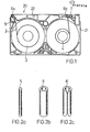
- the typical tape course in a conventional VHS video cassette 20 is shown in Fig. 1.
- the tape 2 is e.g. Coming from the coil 3 with its layer side over a cylindrical metal pin 5 (Fig. 2a), which is pressed into a corresponding recess of the cassette housing 21 made of plastic.
- the tape 2 is then deflected on the guide 6a, which is also fixed, and is guided along the cassette front 22 to the guide 6b.
- the guides 6a and 6b usually consist of seamless metallic hollow cylinders (Fig. 2b) or are bent from a sheet metal strip into a hollow cylinder (6 'in Fig. 2c) (according to DE-OS 28 17 316). From the guide 6b, the tape 2 is guided past the line roller 7 to the spool 4 and wound up there.
- tape guide devices 10a and 11a and 10b and 11b are shown, which correspond to the known guide elements 6a and 6b in the arrangement in the cassette 20.
- a guide element 10a or 10b according to the invention is shown in perspective on a larger scale in FIG.
- a guide belt 8 consists of foil material e.g. a metal foil and has, e.g. by bending, deformed bent or kinked outer edges 9a and 9b.
- the film is compressed from its extended position into an arcuate shape and placed over a post 10.
- the film compressed in the shape of drops or pears has a diameter which is somewhat smaller than the diameter of the post 10.
- the post 10 can be provided with an insertion bevel (not shown) for easier assembly of the bent metal foil 8 and, as a rule, slightly higher or lower (For example, about half as high) as the width of the metal foil 8.
- a holding element here designed as a slotted hollow cylinder 11, is provided in the immediate vicinity of the post 10.
- the slot 12 has a width that is at least somewhat larger than twice the thickness D of the guide belt 8.
- the slotted hollow cylinder 11 is selected to be approximately the same height as the post 10. As tests have shown, however, the guide band is still sufficiently secured in its position when the slotted hollow cylinder 11 is only approximately half the height of the post 10 .
- the guide band can also be inserted or clamped between the upper and lower parts (possibly the cassette housing).
- a safety pin 23 is shown, which tapers slightly conically and fastens to the cover part of the housing 21, e.g. molded, can be.
- the film 8 engages in the opening of the slotted hollow cylinder 11, if desired, so that it can also be fixed.
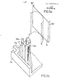
- Figure 5 shows a tape guide device as a replacement for the guide pin 5 (Fig. 1).
- the guide device according to the invention is formed by means of a pin 13 which is connected in one piece to the housing 21, the guide band 8 'is bent around this pin (a dashed intermediate form of the band is shown in FIG. 5A) and with its bent outer edges 9a', 9b 'between am Housing 21 attached holding elements, here between holding projections 14a and 14b, hung.
- the lower dimensioning limit given above for the slot 12 applies to the distance 12 'of the holding projections 14a and 14b from one another.
- Protrusions 14a and 14b can expediently be formed in one piece with lateral housing walls 24. Otherwise, the walls themselves or slots or grooves in inner wall parts of the housing 21 can also be used for the holding purpose.
- holding elements are separate clamping elements which clamp the ends of the guide band together.
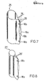
- FIG. 6 A further advantageous form of the tape guide device according to the invention is shown in FIG. 6, in which the guide tape 8 ′′ consists of a central part 16, the length of which is selected to be slightly smaller than the circumference of the pin 13.
- the guide band 8 ′′ if necessary by spring action, automatically fits tightly on the largest part of the pin circumference and cannot slip, even if there is no further bend 17a / b of the guide band ends for hanging on the housing projections 14a / b.
- This version requires a resilient material, but this does not have to be the case with the other versions.
- Figures 7 and 8 show a further embodiment of the tape guiding device, which differs from the other embodiments in that the end portions 26, 26 'of the guide band 25, 25' are joined together prior to assembly, for example by spot welding or by Toggle d ere known connection methods, such as, for example, flanging the ends, etc.
- the end sections 26, 26 ' are connected at the top and bottom at the points 18a / b and the middle parts 19a and 19b of the end sections 26 are bent away from one another or away from their longitudinal axis, so that the bulge w is slightly larger than the width of the slot 12 of the slot hollow cylinder 11 or as the distance 12 'between the projections 14a and 14b.
- the tape guide according to the invention offers exceptionally great economic advantages.
- the material saving in comparison with a tape guide according to FIG. 2b alone is more than 80% when using a 30 ⁇ m metal foil and even more with a 20 ⁇ m foil.
- the invention also has advantages in terms of logistics and assembly, since the guide belt can be obtained as a tape wrap and can be processed particularly cheaply in an automatic production.
- the metal foils can also be subjected to a previous special surface treatment, plating, lapping, polishing, lubricating, etc. If special surface structures are required, these can be continuously impressed onto the metal foil in a simple manner.
- the tape guide according to the invention can also be produced using a plastic film.
- Suitable are e.g. Films made of high-strength and resistant plastics such as polyamideimide, polyetherimide, polysulfones, polyphenylene sulfide, etc.
- the thickness of the guide band is (first) at most about 150 ⁇ m or (second) at most 100 ⁇ m and is practically advantageously between about 10 and 50 ⁇ m or about 10 and 80 ⁇ m.
- Metal foils with 30 and 20 ⁇ m thickness have proven to be excellent, but other materials with other thicknesses can also be used.
- This thickness dimensioning ensures that microstructures based on rough machining on posts 10 or 13 are covered by the guide band and the surface can thereby easily obtain a high surface quality.
- the thickness can also be chosen so that macrostructures, e.g. a pattern on the post is molded outwards, e.g. to create a desired waviness of the guide surface.
- Special band guide cross-sectional contours i.e.
- shapes can also be roughly shaped with the shape of the post and can be refined or compensated for by attaching the guide band.
- the range from approx. 10 to approx. 80 ⁇ m of a metal foil, e.g. a spring steel foil, ensures in any case that there is sufficient flexibility of the guide belt in any case. With other materials, these areas can be somewhere else, but in any case below 150 ⁇ m.
- Base body and holding elements according to the present invention can be formed on one or more housing parts such as pins, pins, walls, etc., or be supported on them.
- FIGS. 9 to 12 A further embodiment of the guiding device is shown in FIGS. 9 to 12.
- FIG. 9 shows the metal foil strip 27 cut, punched and, for example, cut off at the ends 31, 32 once from the metal foil strip.
- the bending angle ⁇ is preferably chosen to be ⁇ 90 ° (less than 90 °) and> .45 0 (greater than 45 °) .
- the cylinder body shown as a support sleeve 29 in Fig. 10, consists of an economically producible, injection-molded plastic, e.g. Polystyrene. Appropriately on a surface line of the cylinder outer surface, two cutouts 33 are arranged as fastening slots and a radially projecting short pin 28.
- the metal foil strip 27 When mounting the metal foil strip 27 on the support sleeve 29, for example, as shown in FIG. 11, first the opening 30a is hooked onto the pin 29, the metal foil strip 27 is wrapped around the cylinder outer surface 34 of the support sleeve 29 and then at the other end also at the opening 36 Pin 28 suspended.
- the metal foil 27 has so much resilient flexibility at the bending or buckling edges 35 and 36 that this process is easy to carry out and that the metal foil 27 automatically catches after being hung on the pin 28 and can only be dismantled therefrom with tools.
- the tape guide device or metal foil guide preassembled in this way can then be stored in a magazine and fed to the cassette assembly device for automatic assembly. There it can then be plugged into the lower part of the cassette housing 37 shown in FIG. 12, for example on a hollow pin 39a.
- This hollow pin 39 has, for example on its foot on its side facing away from the belt path, a projection 40 which engages in a slot 33 of the support sleeve 29 and prevents it from rotating.
- a correspondingly shaped housing rib rests on the flattened surface 4 1 of the attached metal foil 27 or on the pin 28 of the support sleeve 29.
- the upper housing part 38 is placed with the upper hollow pin 39b and e.g. screwed with screws 42.
- the construction of the tape guide element according to the invention consisting of metal foil and a support body that can be separated from the tape transport device, has the advantage that significant changes to the tape transport device, in particular to a tape cassette, are not necessary.
- the pre-assembly on the support bodies, in particular the support sleeves, requires e.g. only minor modifications to the cassette housing, which can be easily retrofitted to existing tools.
- the assembly of the 'sleeves is possible with conventional machines.
- tape guide devices described also primarily reproduce or subsequently perfect fixed tape guide elements can, however, also movably arranged, for example pivotable or displaceable guides can thus be formed with the same advantages.
- Modifications to the base body e.g. Structures, rings, etc. are also possible, as are variants of similar suitable materials, in particular plastics, such as variants of foils with or without surface structures, different expansion coefficients, etc.
Landscapes
- Registering, Tensioning, Guiding Webs, And Rollers Therefor (AREA)
Priority Applications (1)
| Application Number | Priority Date | Filing Date | Title |
|---|---|---|---|
| AT85116041T ATE44328T1 (de) | 1984-12-24 | 1985-12-16 | Bandfuehrungsvorrichtung fuer bandtransporteinrichtungen, insbesondere magnetbandeinrichtungen, und bandkassetten damit. |
Applications Claiming Priority (4)
| Application Number | Priority Date | Filing Date | Title |
|---|---|---|---|
| DE19848438028 DE8438028U1 (de) | 1984-12-24 | 1984-12-24 | Bandfuehrungsvorrichtung fuer bandtransporteinrichtungen insbesondere magnetbandeinrichtungen |
| DE8438028U | 1984-12-24 | ||
| DE19858516444 DE8516444U1 (de) | 1985-06-05 | 1985-06-05 | Bandführungsvorrichtung für Bandtransporteinrichtungen, insbesondere Magnetbandeinrichtungen |
| DE8516444U | 1985-06-05 |
Publications (2)
| Publication Number | Publication Date |
|---|---|
| EP0187319A1 true EP0187319A1 (fr) | 1986-07-16 |
| EP0187319B1 EP0187319B1 (fr) | 1989-06-28 |
Family
ID=25950123
Family Applications (1)
| Application Number | Title | Priority Date | Filing Date |
|---|---|---|---|
| EP85116041A Expired EP0187319B1 (fr) | 1984-12-24 | 1985-12-16 | Mécanisme de guidage de bande pour dispositifs d'entraînement de bande, particulièrement dispositifs de bande magnétique, et cassettes à bande avec ce mécanisme |
Country Status (4)
| Country | Link |
|---|---|
| US (1) | US4736904A (fr) |
| EP (1) | EP0187319B1 (fr) |
| JP (1) | JPH0658758B2 (fr) |
| DE (1) | DE3571285D1 (fr) |
Cited By (5)
| Publication number | Priority date | Publication date | Assignee | Title |
|---|---|---|---|---|
| EP0217157A1 (fr) * | 1985-09-02 | 1987-04-08 | Asahi Polyslider Co., Ltd. | Guide de bande pour cassette de bande vidéo |
| EP0271978A3 (en) * | 1986-12-15 | 1989-05-24 | Sanwa Needle Bearing Co., Ltd. | Composite tape guide for a vtr tape cassette |
| EP0283560A3 (fr) * | 1987-03-25 | 1990-04-25 | KOLLER MANUFACTURING CORPORATION (a Wisconsin corporation) | Cassette à bande magnétique |
| EP0563640A1 (fr) * | 1992-03-13 | 1993-10-06 | Sony Corporation | Dispositif de guidage pour une bande magnétique |
| EP0932154A1 (fr) * | 1998-01-23 | 1999-07-28 | TDK Corporation | Cassette à bande |
Families Citing this family (18)
| Publication number | Priority date | Publication date | Assignee | Title |
|---|---|---|---|---|
| US5246298A (en) * | 1986-07-15 | 1993-09-21 | Monarch Marking Systems, Inc. | Ink ribbon cartridge and installation methods relating thereto |
| US5051009A (en) * | 1986-07-15 | 1991-09-24 | Monarch Marking Systems, Inc. | Printhead mount & cassette lock in a thermal printer |
| US4878632A (en) * | 1987-03-25 | 1989-11-07 | Koller Manufacturing Corporation | Magnetic tape cassettes |
| US4770367A (en) * | 1987-03-25 | 1988-09-13 | Carroll William M | Magnetic tape cassettes |
| JPH0171383U (fr) * | 1987-10-29 | 1989-05-12 | ||
| US4991047A (en) * | 1987-11-09 | 1991-02-05 | Tdk Corporation | Tape guides and method of manufacturing the same |
| DE8808630U1 (de) * | 1988-07-06 | 1988-09-15 | Basf Ag, 6700 Ludwigshafen | Kassette für einen Bandaufzeichnungsträger, insbesondere ein Magnetband |
| US5074451A (en) * | 1989-12-20 | 1991-12-24 | Minnesota Mining And Manufacturing Company | Plastic tape guide for videocassette |
| US5201476A (en) * | 1990-05-11 | 1993-04-13 | Paul J. Gelardi | Welded video cassette |
| US5092536A (en) * | 1990-05-11 | 1992-03-03 | Paul J. Gelardi | Integrally molded recyclable video tape cassette |
| US5390063A (en) * | 1991-03-19 | 1995-02-14 | Plitek Corporation | Video cassette pressure flap |
| EP0536912B1 (fr) * | 1991-10-09 | 1997-12-29 | Minnesota Mining And Manufacturing Company | Guide de bande pour cassette de données |
| JPH05198135A (ja) * | 1992-01-22 | 1993-08-06 | Hitachi Ltd | 磁気テープカセット |
| US5299756A (en) * | 1992-10-26 | 1994-04-05 | International Business Machines Corporation | Foil wrapped flexible web guide |
| US5377927A (en) * | 1993-07-01 | 1995-01-03 | Minnesota Mining And Manufacturing Company | Tape guide for a data cartridge |
| US5513815A (en) * | 1993-07-01 | 1996-05-07 | Minnesota Mining And Manufacturing Company | Tape guide module for a data cartridge |
| US6295181B1 (en) * | 1996-06-14 | 2001-09-25 | Imation Corp. | Tape bearing surface with reduce tape contact and method of making same |
| JP3614633B2 (ja) * | 1997-12-22 | 2005-01-26 | 富士写真フイルム株式会社 | 磁気テープカートリッジ |
Citations (5)
| Publication number | Priority date | Publication date | Assignee | Title |
|---|---|---|---|---|
| DE2501866A1 (de) * | 1974-01-18 | 1975-07-24 | Sony Corp | Bandkassette |
| DE2808998A1 (de) * | 1978-03-02 | 1979-09-13 | Bosch Gmbh Robert | Feststehende kopftrommel fuer bandaufnahme- und wiedergabegeraete |
| GB1584630A (en) * | 1976-12-30 | 1981-02-18 | Bosch Gmbh Robert | Recording and/or reproduction apparatus for magnetic tapes |
| DE2840069B2 (de) * | 1977-09-14 | 1981-05-27 | Yozaburo Tokyo Umehara | Bandführungseinrichtung für ein Aufzeichnungs- und/oder Wiedergabegerät, sowie Herstellverfahren dafür |
| DE3425401A1 (de) * | 1983-07-11 | 1985-01-24 | Tdk Corp., Tokio/Tokyo | Magnetbandkassette |
Family Cites Families (11)
| Publication number | Priority date | Publication date | Assignee | Title |
|---|---|---|---|---|
| US3658227A (en) * | 1970-04-03 | 1972-04-25 | John F Stephens | Tape guide spindle |
| US3889900A (en) * | 1973-08-01 | 1975-06-17 | Alexander Sell Steldt & Delahu | Cartridge tape guide |
| DE2535276C2 (de) * | 1975-08-07 | 1984-07-26 | Basf Ag, 6700 Ludwigshafen | Großflächige Bandführungseinrichtung für Magnetbandgeräte und Verfahren zur Herstellung derselben |
| DE2722509C2 (de) * | 1977-05-18 | 1987-05-14 | Basf Ag, 6700 Ludwigshafen | Bandführungseinrichtung für schnellaufende Magnetbandgeräte |
| JPS53160925U (fr) * | 1977-05-25 | 1978-12-16 | ||
| US4437222A (en) * | 1977-09-14 | 1984-03-20 | Yozaburo Umehara | Method of manufacturing tape guides for recording and/or reproducing apparatus |
| JPS615659Y2 (fr) * | 1980-01-14 | 1986-02-20 | ||
| JPS5834619Y2 (ja) * | 1980-01-14 | 1983-08-03 | ティーディーケイ株式会社 | 磁気テ−プカセット |
| JPS57122084U (fr) * | 1981-01-21 | 1982-07-29 | ||
| JPS57184583U (fr) * | 1981-05-18 | 1982-11-24 | ||
| JPS6193878U (fr) * | 1984-11-27 | 1986-06-17 |
-
1985
- 1985-12-13 JP JP60279419A patent/JPH0658758B2/ja not_active Expired - Lifetime
- 1985-12-16 DE DE8585116041T patent/DE3571285D1/de not_active Expired
- 1985-12-16 EP EP85116041A patent/EP0187319B1/fr not_active Expired
- 1985-12-24 US US06/813,231 patent/US4736904A/en not_active Expired - Fee Related
Patent Citations (5)
| Publication number | Priority date | Publication date | Assignee | Title |
|---|---|---|---|---|
| DE2501866A1 (de) * | 1974-01-18 | 1975-07-24 | Sony Corp | Bandkassette |
| GB1584630A (en) * | 1976-12-30 | 1981-02-18 | Bosch Gmbh Robert | Recording and/or reproduction apparatus for magnetic tapes |
| DE2840069B2 (de) * | 1977-09-14 | 1981-05-27 | Yozaburo Tokyo Umehara | Bandführungseinrichtung für ein Aufzeichnungs- und/oder Wiedergabegerät, sowie Herstellverfahren dafür |
| DE2808998A1 (de) * | 1978-03-02 | 1979-09-13 | Bosch Gmbh Robert | Feststehende kopftrommel fuer bandaufnahme- und wiedergabegeraete |
| DE3425401A1 (de) * | 1983-07-11 | 1985-01-24 | Tdk Corp., Tokio/Tokyo | Magnetbandkassette |
Cited By (6)
| Publication number | Priority date | Publication date | Assignee | Title |
|---|---|---|---|---|
| EP0217157A1 (fr) * | 1985-09-02 | 1987-04-08 | Asahi Polyslider Co., Ltd. | Guide de bande pour cassette de bande vidéo |
| EP0271978A3 (en) * | 1986-12-15 | 1989-05-24 | Sanwa Needle Bearing Co., Ltd. | Composite tape guide for a vtr tape cassette |
| EP0283560A3 (fr) * | 1987-03-25 | 1990-04-25 | KOLLER MANUFACTURING CORPORATION (a Wisconsin corporation) | Cassette à bande magnétique |
| EP0563640A1 (fr) * | 1992-03-13 | 1993-10-06 | Sony Corporation | Dispositif de guidage pour une bande magnétique |
| EP0932154A1 (fr) * | 1998-01-23 | 1999-07-28 | TDK Corporation | Cassette à bande |
| US6191920B1 (en) | 1998-01-23 | 2001-02-20 | Tdk Corporation | Tape cassette with tape guides press-fit over ribbed guide posts |
Also Published As
| Publication number | Publication date |
|---|---|
| US4736904A (en) | 1988-04-12 |
| DE3571285D1 (en) | 1989-08-03 |
| EP0187319B1 (fr) | 1989-06-28 |
| JPS61192093A (ja) | 1986-08-26 |
| JPH0658758B2 (ja) | 1994-08-03 |
Similar Documents
| Publication | Publication Date | Title |
|---|---|---|
| EP0187319B1 (fr) | Mécanisme de guidage de bande pour dispositifs d'entraînement de bande, particulièrement dispositifs de bande magnétique, et cassettes à bande avec ce mécanisme | |
| DE3306284A1 (de) | Schlauchklemme | |
| DE2431969B2 (de) | Bandkassette | |
| DE2441386B2 (de) | Bandspule | |
| DE1160677B (de) | Kassetteneinrichtung fuer bandfoermige Aufzeichnungstraeger | |
| DE69109892T2 (de) | Lager. | |
| DE3132582C2 (de) | Spule für Videokassetten | |
| DE2837888A1 (de) | Bandkassette | |
| DE1919882C3 (de) | Drehbare Trommel | |
| DE2210709A1 (de) | Magnetbandspulenkassette | |
| DE3884864T2 (de) | Einrichtung zur Positionierung einer Spule. | |
| DE8014018U1 (de) | Freilaufkupplung | |
| DE3130877C3 (de) | Magnetbandkassette | |
| DE2623150C3 (de) | Spulenkörper für eine Magnetbandkassette | |
| EP0051145A1 (fr) | Noyau d'enroulement pour cassettes de bande magnétique, en particulier cassettes compactes et cassettes de bande magnétique ayant au moins un noyau d'enroulement | |
| DE19856688B4 (de) | Magnethaltestruktur für einen Linearmotor | |
| DE2930647C2 (de) | Spulenkern für eine Bandkassette | |
| DE2535276C2 (de) | Großflächige Bandführungseinrichtung für Magnetbandgeräte und Verfahren zur Herstellung derselben | |
| DE8606397U1 (de) | Bandklammer für eine Bandspule mit oder ohne mindestens einen Seitenflansch und dafür geeignete Bandspule | |
| DE19739520A1 (de) | Vorrichtung zum Wickeln eines dünnen flachen Leiterdrahts in Hochkantstellung | |
| DE3151103A1 (de) | Bandkassettengeraet | |
| DE10230882B4 (de) | Verfahren zum Herstellen einer Rolle | |
| DE8438028U1 (de) | Bandfuehrungsvorrichtung fuer bandtransporteinrichtungen insbesondere magnetbandeinrichtungen | |
| DE1293221B (de) | Spule fuer bandfoermige Aufzeichnungstraeger | |
| DE3341866A1 (de) | Mehrreihiges rollenlager |
Legal Events
| Date | Code | Title | Description |
|---|---|---|---|
| PUAI | Public reference made under article 153(3) epc to a published international application that has entered the european phase |
Free format text: ORIGINAL CODE: 0009012 |
|
| AK | Designated contracting states |
Kind code of ref document: A1 Designated state(s): AT BE DE FR GB NL |
|
| RIN1 | Information on inventor provided before grant (corrected) |
Inventor name: BUHK, ARTUR Inventor name: GAISER, DIETER Inventor name: MUENZNER, WULF, DR. Inventor name: DIETZE, HERBERT Inventor name: KAMM, EUGEN Inventor name: SCHMIDTS, KURT Inventor name: GLINIORZ, LOTHAR Inventor name: SCHOETTLE, KLAUS |
|
| 17P | Request for examination filed |
Effective date: 19860904 |
|
| 17Q | First examination report despatched |
Effective date: 19880120 |
|
| GRAA | (expected) grant |
Free format text: ORIGINAL CODE: 0009210 |
|
| AK | Designated contracting states |
Kind code of ref document: B1 Designated state(s): AT BE DE FR GB NL |
|
| REF | Corresponds to: |
Ref document number: 44328 Country of ref document: AT Date of ref document: 19890715 Kind code of ref document: T |
|
| REF | Corresponds to: |
Ref document number: 3571285 Country of ref document: DE Date of ref document: 19890803 |
|
| GBT | Gb: translation of ep patent filed (gb section 77(6)(a)/1977) | ||
| ET | Fr: translation filed | ||
| PLBE | No opposition filed within time limit |
Free format text: ORIGINAL CODE: 0009261 |
|
| STAA | Information on the status of an ep patent application or granted ep patent |
Free format text: STATUS: NO OPPOSITION FILED WITHIN TIME LIMIT |
|
| 26N | No opposition filed | ||
| PGFP | Annual fee paid to national office [announced via postgrant information from national office to epo] |
Ref country code: FR Payment date: 19931115 Year of fee payment: 9 |
|
| PGFP | Annual fee paid to national office [announced via postgrant information from national office to epo] |
Ref country code: AT Payment date: 19931123 Year of fee payment: 9 |
|
| PGFP | Annual fee paid to national office [announced via postgrant information from national office to epo] |
Ref country code: GB Payment date: 19931215 Year of fee payment: 9 Ref country code: DE Payment date: 19931215 Year of fee payment: 9 |
|
| PGFP | Annual fee paid to national office [announced via postgrant information from national office to epo] |
Ref country code: BE Payment date: 19931224 Year of fee payment: 9 |
|
| PGFP | Annual fee paid to national office [announced via postgrant information from national office to epo] |
Ref country code: NL Payment date: 19931231 Year of fee payment: 9 |
|
| PG25 | Lapsed in a contracting state [announced via postgrant information from national office to epo] |
Ref country code: GB Effective date: 19941216 Ref country code: AT Effective date: 19941216 |
|
| PG25 | Lapsed in a contracting state [announced via postgrant information from national office to epo] |
Ref country code: BE Effective date: 19941231 |
|
| BERE | Be: lapsed |
Owner name: BASF A.G. Effective date: 19941231 |
|
| PG25 | Lapsed in a contracting state [announced via postgrant information from national office to epo] |
Ref country code: NL Effective date: 19950701 |
|
| GBPC | Gb: european patent ceased through non-payment of renewal fee |
Effective date: 19941216 |
|
| PG25 | Lapsed in a contracting state [announced via postgrant information from national office to epo] |
Ref country code: FR Effective date: 19950831 |
|
| NLV4 | Nl: lapsed or anulled due to non-payment of the annual fee |
Effective date: 19950701 |
|
| PG25 | Lapsed in a contracting state [announced via postgrant information from national office to epo] |
Ref country code: DE Effective date: 19950901 |
|
| REG | Reference to a national code |
Ref country code: FR Ref legal event code: ST |