EP0187326B1 - Manipulateur et procédé pour mouvoir des éléments d'une base dans leur position de montage - Google Patents
Manipulateur et procédé pour mouvoir des éléments d'une base dans leur position de montage Download PDFInfo
- Publication number
- EP0187326B1 EP0187326B1 EP85116165A EP85116165A EP0187326B1 EP 0187326 B1 EP0187326 B1 EP 0187326B1 EP 85116165 A EP85116165 A EP 85116165A EP 85116165 A EP85116165 A EP 85116165A EP 0187326 B1 EP0187326 B1 EP 0187326B1
- Authority
- EP
- European Patent Office
- Prior art keywords
- mast
- erected
- manipulator
- large panel
- wall
- Prior art date
- Legal status (The legal status is an assumption and is not a legal conclusion. Google has not performed a legal analysis and makes no representation as to the accuracy of the status listed.)
- Expired - Lifetime
Links
- 238000000034 method Methods 0.000 title claims description 18
- 125000006850 spacer group Chemical group 0.000 claims description 3
- 238000009434 installation Methods 0.000 description 5
- 238000005452 bending Methods 0.000 description 3
- XEEYBQQBJWHFJM-UHFFFAOYSA-N Iron Chemical compound [Fe] XEEYBQQBJWHFJM-UHFFFAOYSA-N 0.000 description 2
- 235000000396 iron Nutrition 0.000 description 2
- 230000002787 reinforcement Effects 0.000 description 2
- 229910000831 Steel Inorganic materials 0.000 description 1
- 239000000853 adhesive Substances 0.000 description 1
- 230000001070 adhesive effect Effects 0.000 description 1
- 230000005540 biological transmission Effects 0.000 description 1
- 239000004568 cement Substances 0.000 description 1
- 239000003795 chemical substances by application Substances 0.000 description 1
- 238000010276 construction Methods 0.000 description 1
- 230000001419 dependent effect Effects 0.000 description 1
- 238000010586 diagram Methods 0.000 description 1
- 238000009415 formwork Methods 0.000 description 1
- 238000011900 installation process Methods 0.000 description 1
- 229910052742 iron Inorganic materials 0.000 description 1
- 238000004519 manufacturing process Methods 0.000 description 1
- 230000007246 mechanism Effects 0.000 description 1
- 239000004570 mortar (masonry) Substances 0.000 description 1
- 238000005192 partition Methods 0.000 description 1
- 239000010959 steel Substances 0.000 description 1
- 239000000725 suspension Substances 0.000 description 1
- 238000003466 welding Methods 0.000 description 1
- 238000004804 winding Methods 0.000 description 1
Images

Classifications
-
- E—FIXED CONSTRUCTIONS
- E04—BUILDING
- E04G—SCAFFOLDING; FORMS; SHUTTERING; BUILDING IMPLEMENTS OR AIDS, OR THEIR USE; HANDLING BUILDING MATERIALS ON THE SITE; REPAIRING, BREAKING-UP OR OTHER WORK ON EXISTING BUILDINGS
- E04G21/00—Preparing, conveying, or working-up building materials or building elements in situ; Other devices or measures for constructional work
- E04G21/14—Conveying or assembling building elements
- E04G21/16—Tools or apparatus
-
- E—FIXED CONSTRUCTIONS
- E04—BUILDING
- E04B—GENERAL BUILDING CONSTRUCTIONS; WALLS, e.g. PARTITIONS; ROOFS; FLOORS; CEILINGS; INSULATION OR OTHER PROTECTION OF BUILDINGS
- E04B1/00—Constructions in general; Structures which are not restricted either to walls, e.g. partitions, or floors or ceilings or roofs
- E04B1/35—Extraordinary methods of construction, e.g. lift-slab, jack-block
- E04B1/355—Extraordinary methods of construction, e.g. lift-slab, jack-block characterised by the tilting up of whole buildings or sections thereof, e.g. walls, portal frames
-
- E—FIXED CONSTRUCTIONS
- E04—BUILDING
- E04G—SCAFFOLDING; FORMS; SHUTTERING; BUILDING IMPLEMENTS OR AIDS, OR THEIR USE; HANDLING BUILDING MATERIALS ON THE SITE; REPAIRING, BREAKING-UP OR OTHER WORK ON EXISTING BUILDINGS
- E04G21/00—Preparing, conveying, or working-up building materials or building elements in situ; Other devices or measures for constructional work
- E04G21/14—Conveying or assembling building elements
- E04G21/16—Tools or apparatus
- E04G21/167—Tools or apparatus specially adapted for working-up plates, panels or slab shaped building elements
- E04G21/168—Tools or apparatus specially adapted for working-up plates, panels or slab shaped building elements used for tilting, e.g. from horizontal to vertical position or vice versa
-
- E—FIXED CONSTRUCTIONS
- E04—BUILDING
- E04B—GENERAL BUILDING CONSTRUCTIONS; WALLS, e.g. PARTITIONS; ROOFS; FLOORS; CEILINGS; INSULATION OR OTHER PROTECTION OF BUILDINGS
- E04B1/00—Constructions in general; Structures which are not restricted either to walls, e.g. partitions, or floors or ceilings or roofs
- E04B1/35—Extraordinary methods of construction, e.g. lift-slab, jack-block
- E04B2001/3588—Extraordinary methods of construction, e.g. lift-slab, jack-block using special lifting or handling devices, e.g. gantries, overhead conveying rails
Definitions
- the invention relates to a manipulator for moving large panels and / or other parts lying on a base, preferably produced there, with a mast which can be tilted about at least one axis on the base and which has a winch for winding and unwinding a rope from carries a pulley, and with at least one fastening means which can be fastened to the large board and / or the part to be erected above the axis, so that the large board and / or the part to be erected can be erected by rotating the winch, the pulley unit having at least one upper one , Mounted on the mast roller and at least one lower roller, which is suspended in a loose rope loop and on which the fastening means for the large board and / or the part to be erected is mounted, and a method which can be carried out by means of such a manipulator for moving on a Underlying, preferably made there large panel n and / or other finished parts.
- a manipulator of the above type is shown in AU-B-488 362, in which a tilting moment acts on the mast during the erection process, which is particularly difficult to control at the start of the erection process and permanently exerts a bending moment on the mast. It is therefore difficult to pick up longer parts inasmuch as high bending moments occur in the sheet due to the manipulator acting only at one point on the sheets, which could cause damage.
- AU-B-497 442 discloses a method for erecting a house by erecting large panels erected as outer walls of the house in a horizontal position on a support.
- the invention has for its object to develop a manipulator of the type mentioned in such a way that no bending moments act on the mast and long parts can be safely lifted.
- This object is solved by the subject matter of claim 1.
- a further development of this manipulator according to claim 2 makes it possible in a simple manner to lift loads located directly next to an already erected large board.
- the invention is further based on the object of proposing a method with which, with the aid of the manipulator according to the invention, the large panels and other finished parts to be assembled into a building can easily be brought into their installation position.
- the last-mentioned object is achieved according to the invention by the subject matter of claim 3.
- a preferred development of the method is the subject of dependent claim 4.
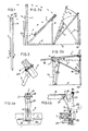
- FIG. 1 shows a known manipulator 1 for erecting parts made lying flat. It consists of a mast 19, which can be made from a one-piece square tube or from a length-adjustable formwork support. He also has an upper roller 2, over which a rope 5 runs, on which a hook 3 is attached. You can pull the rope 5 with a winch 4.
- wall and ceiling parts should be connected approximately every 2 m. From this, as well as from the consideration of not making the assembly reinforcement stronger than the ring anchor reinforcement that is necessary anyway, there are reasonable mast spacings of 2 m.
- Figure 5 shows a variant with two hooks 33a and 33b. It has two upper rollers 2a, 2b and two lower rollers 15a, 15b.
- the rope 5 now runs from the winch 4 in succession over the upper roller 2a, the roller 15b, the upper roller 2b (FIG. 6), and the roller 15a to a fastening hook 43, which can also be designed as a thimble and fastened to the upper mast end is.
- a pulley system with two upper and two lower rollers is obtained, the lower rollers being dissolved. The number of rolls can of course be increased in order to use even more hooks.
- the mast 19 is inserted into a distributor foot 30, which in turn is placed on a support beam 31 (FIG. 7).
- the support beam 31 lies with the interposition of a soft cushion 32 on the base plate 8. It meets the structural requirements if it is 1.5 m long.
- the erection process known per se is sketched on the left in FIG. 2a for erecting a wall part 6.
- the wall part and the support do not slide apart during the process if the coefficient of friction between the part and the base is greater than 0.23 and between the cushion 32 and the base is greater than 0.7 (theoretical values). Of course, you will still take safety precautions.
- Figures 2a and 2b show wall parts 6 and ceiling parts 7, which were cast and erected one after the other on a base plate 8, namely first the outer walls 6a and the transverse walls, not shown, then the ceiling parts 7 and 7a, lastly the central longitudinal wall 6b.
- the walls are already connected to each other so that they stand securely. If you only want to work on the base plate 8, you need five work cycles to complete all parts of a floor. When using cement of the strength classes Z45F and Z55, you need 3 days for each cycle. If you use thick large-area switchboards as a release agent, you can also nest so that all parts of a floor are manufactured in one cycle. This is also advantageous in the cold.
- the ceiling part 7 is lowered with the aid of the manipulators 1 into the position shown in dashed lines (FIG. 2a) and leaned against commercially available inclined supports 9.
- Devices which can be formed by a screw connection 44 according to FIG. 3, ensure that the part does not slip away. If the part is a plate beam, the inclined support 9 can engage in the throat 13 with a correspondingly shaped head.
- the manipulators 1 provided with additional devices 14 are now placed on the walls 6a, 6b. Since the foot 30 would interfere, it is removed.
- the rope 5 is placed around a lower roller 15, which engages with a hook 16 on extensions of the lower edge 12 of the ceiling part 7.
- the hook 3 of the rope 5 is fastened to the upper edge 24 of the additional part 14 (FIGS. 4a and 4b).
- the winch 4 By turning the winch 4, the ceiling part 7 is now raised.
- the inclined support 9 moves with the upper edge of the part 7 towards the wall 6b. This is shortly before reaching the installation position (dashed line in Figure 2b) Cover part 7 by the support dimension on the wall 6a over the wall 6b.
- the inclined support 9 is adjusted so that the part 7 can slide over the part 7a. Otherwise, the manipulators 1 are placed on blocks 17, which are somewhat thinner than the ceiling part 7. Before the installation position is reached, the upper edge 18 of the ceiling raises the manipulator somewhat and the blocks can be removed. During the lifting, the part 7 exerts a horizontal force against the wall 6a. This is taken up by slide strips, not shown, which are attached to the ends of the ceiling part 7.
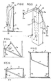
- FIGS. 4a and 4b show one possibility for a single manipulator.
- the additional part 14 consists of two irons 22 which are connected at the bottom by a foot 23 and at the top by a cross connection 24.
- the part 14 is rigidly connected to the mast 19 by pushing it with elongated holes 25 over the shaft 20 of the upper roller 2 projecting for this purpose and pushing a bolt 21 through holes 26 in the iron 22 and in the mast 19 and using suitable ones Devices locked.
- the foot 23 has a soft cushion 27, preferably made of structural rubber, which is attached so that the load is transferred to the inside of the wall 6a.
- the wall 6a has recesses at the contact point, which ensure that the foot is not pinched. Together with corresponding recesses in the ceiling part, they will later be used for the transmission of thrust.
- the distance between the irons 22 is chosen so that the lower roller 15 fits in together with its suspension device. This ensures that the ceiling part 7 can overshoot somewhat when it is over the top of the wall 6a slips. You can also use a brake pad 28, which causes the ceiling part 7 to start up on a slope when it swings. The ceiling part 7 is now raised a little further. The brake pad 28 is removed. Adhesive mortar is introduced. The exact adjustment of the horizontal position is possible without great effort (for example by lifting the lower edge of the mast 19).
- the additional part 14a represents a possibility of ceiling mounting with a two-hook manipulator la.
- it is similar to part 14, except that the vertical bars 22a and 22b are further apart, above by an approximately 1.5 m long Cross connection 24a are connected and have individual feet 23a and 23b.
- the part 14a has a deflection 25 and rollers 26, 27 and 28.
- the rope 5 runs from the fastening hook 43 via the deflection 25, the rollers 15a, 26, 27, 15b, 28 and 2a to the winch 4.
- the erection process can take place in the form already described. According to FIG. 9, horizontal movements of the already raised ceiling part 7 are also possible by lifting the lower end of the mast 19a. In a similar way, the ceiling installation is possible in a manner not shown, even with the pulley broken.
- FIG. 12 shows the principle of operation of a possible embodiment of a single-hook Pull-out manipulator.
- the mast consists of nested parts 19d and 19e.
- the inner mast 19e has an upper and lower roller 2e, 2f.
- the outer mast 19d carries the upper roller 2d and the winch 4.
- the rope 5 runs from the winch 4 over the rollers 2d, 2f and 2e to the hook 3.
- a stop 39 ensures that the guidance takes place with the least possible play.
- FIG. 13 The diagram of a two-hook pull-out manipulator is shown in FIG. 13.
- the rope 5 runs successively from the winch 4 over the rollers 2m, 2k, 2h, 15b, 2i, 15a, 2g and 2e to a fastening 38 located on the outer mast 19d.
- the rollers 2e, 2k, 2g, 2i, 2h are firmly connected to the inner mast 19e.
- Gradual inclination of the rope reduces the vertical component of the force on the rollers 15a and 15b.
- the inner mast begins to slide out. Shortly before the end of the erection process, the inner mast 19e is prevented from being pushed out further by, for example, pushes a pin through one of the holes 37.
- This two-hook pull-out manipulator is a bit more complicated to set up, but it can be used more universally. Only one such manipulator is required for assembly operations according to FIG.
- a pull-out manipulator can also be an advantage when assembling wider parts, such as complete floor ceilings and wall parts spanning several storeys, since the buckling length is initially relatively small and the load becomes ever smaller with longer pull-out lengths.
- manipulator is primarily suitable for smaller manipulators, which a man preferably uses Hand winch are operated and with which you can assemble parts of a maximum of about 3 m width and any length. If you want to install one-piece floor ceilings and / or multi-storey wall parts, you need larger manipulators, which in turn require handling mechanisms. For example, you could use a small construction crane to move a large manipulator with more than two hooks and use the same crane as a winch. In order to prevent multi-storey walls from breaking up, rigid supports must be put on and connected to the walls.
- Figure 14 shows a variant of a two-story assembly process: the two-storey walls 6d, 6e have cutouts 40 as a ceiling support at half height.
- the two floor ceilings 7d, 7e are first produced on the base plate, then erected and tilted back into the drawn position for final assembly, where they are held by the inclined supports 9d and 9e.
- the final assembly is as described.
- the upper ceiling 7e is installed. It contains sufficiently large cutouts through which the hooks can be passed in order to also mount the ceiling 7d.
- Figure 15 shows a further variant in use in a three-storey installation: here twice as many manipulators but no inclined supports are required. They are placed so that hooks hang down on both walls. The masts are screwed together for safety.
- the ceiling parts are made on top of each other on the base plate. On one side they protrude through recesses 41 on the bottom edge of the wall. For final assembly, the ceiling parts are first raised on one side so that they fit diagonally between the walls. Then can be lifted on both sides and eventually. be assembled.
- FIG. 16 finally shows a combination of the assembly methods according to FIGS. 2a, 2b and 15 for a floor and a complete ceiling part 7k: the ceiling part 7k is first raised to the inclined position and supported with inclined supports 9. Then the other side is raised in a known manner.
- This last variant has the advantages that one has more planning freedom, can manufacture the ceiling and the surrounding walls on top of one another and assemble them in one operation, and can adjust the length of the mast 19 to the maximum wall height.
- the mast has an extension 42.
- the higher ceiling weight is absorbed by designing the rollers 15a, 15b, 26, 27 shown in FIG. 11 as double rollers and doubling the lifting force by the pulley thus formed.
- the ceiling part 7k must be pushed towards the wall 6k, for example by means of winches and crowbars.
- the additional part 14 is advantageous, but not absolutely necessary.
- the ceiling part can be connected to the end walls by welding on suitable steel inserts.
- conventional supports can also be achieved by initially producing and erecting only one end wall and first lowering the ceiling part onto the longitudinal wall 6a during assembly so that low frictional forces occur. In this position, you can slide it horizontally over the front wall and only then completely lower it.
- the second bulkhead will be manufactured and erected later together with the inner walls.
Landscapes
- Engineering & Computer Science (AREA)
- Architecture (AREA)
- Civil Engineering (AREA)
- Structural Engineering (AREA)
- Mechanical Engineering (AREA)
- Physics & Mathematics (AREA)
- Electromagnetism (AREA)
- Conveying And Assembling Of Building Elements In Situ (AREA)
Claims (4)
- Manipulateur pour déplacer des grands panneaux et/ou des éléments cintrés, reposant sur un support, de préférence fabriqués sur place, avec un mât (15) dressé sur le support, pouvant basculer par sa pointe de pied au moins autour d'un axe, lequel mât porte un treuil (4) pour enrouler et dérouler un câble (5) d'une poulie multiple (2a, 2b, 15a, 15b) et avec au moins un moyen de fixation (33a, 33b) qui peut être fixé, au-dessus de l'axe, sur le grand panneau et/ou sur l'élément (6a, 6b, 7) à dresser, de manière que le grand panneau et/ou l'élément à dresser puisse être dressé par rotation du treuil, la poulie multiple comprenant au moins une poulie supérieure (2a, 2b) montée sur le mât et au moins une poulie inférieure (15a, 15b) qui est suspendue dans une boucle lâche de câble respective et sur laquelle est monté le moyen de fixation pour le grand panneau et/ou l'élément à dresser, caractérisé en ce qu'il est prévu au moins deux poulies inférieures (15a, 15b) avec chacune un moyen de fixation (33a, 33b) et en ce que des écarteurs (34) sont disposés sur le bord extérieur côté mat des grands panneaux ou de l'élément à déplacer, de part et d'autre du mât (19), lesquels écarteurs maintiennent les points d'action de la force exercée par les moyens de fixation (33a, 33b) dans un plan parallèle a la direction de la force, passant par l'axe de basculement du mât.
- Manipulateur selon la revendication 1, caractérisé en ce qu'a l'extrémité supérieure du mât (19) peut être fixé un élément supplémentaire (14) qui forme une zone (22) à peu près perpendiculaire au mât (19), destinée à être placée sur un grand panneau ou un élément déjà dressé, l'élément supplémentaire (14a) ayant la forme d'une traverse (24a) et portant, sur ses extrémités extérieures, des poulies de renvoi (26, 27, 28) pour les boucles de câble et possédant au moins deux pieds (23a, 23b) qui font saillie de la traverse (24a), à peu près perpendiculairement à celle-ci et du mât (19), à peu près perpendiculairement à celui-ci, de manière que le manipulateur placé audessus des pieds (23a, 23b), sur la face supérieure d'un grand panneau ou d'un élément déjà dressés, puisse soulever des charges, au moyen du treuil (4), directement à côté du grand panneau ou de l'élément dressés.
- Procédé pour amener dans leur position de montage, des grands panneaux et/ou des élèments préfabriqués cintrés, reposant sur un support, de préférence fabriqués sur place, et servant de planchers, au moyen de manipulateurs selon la revendication 2, caractérisé en ce qu'un grand panneau ou un élément servant de plancher d'étage est amené en position à peu près verticale, par un déplacement circulaire autour d'un côté latéral situé à côté d'un grand panneau déjà dressé, servant de mur extérieur, puis abaissé sur un poteau incliné du commerce et en ce que le grand panneau ou l'élément est amené dans sa position de montage par relevage à peu près vertical le long de la paroi latérale, éventuellement avec un dernier déplacement horizontal.
- Procédé selon la revendication 3 pour le montage de trois murs extérieurs et du plancher d'un étage, caractérisé en ce que le plancher d'étage, deux murs extérieurs opposés et un troisième mur extérieur sont empilés sur le support, dans l'ordre cité, l'un des murs extérieurs opposés étant pourvu à sa partie inférieure d'évidements qui s'emboîtent dans des évidements correspondants de l'élément de plancher inférieur, en ce que les murs extérieurs sont dressés et assemblés entre eux et en ce qu'ensuite le plancher est monté de manière à reposer aussi sur le troisième mur extérieur, par un déplacement horizontal perpendiculaire aux mâts.
Priority Applications (1)
| Application Number | Priority Date | Filing Date | Title |
|---|---|---|---|
| AT85116165T ATE61315T1 (de) | 1984-12-18 | 1985-12-18 | Manipulator und verfahren zur bewegung von auf einer unterlage befindlichen teilen in ihre einbauposition. |
Applications Claiming Priority (4)
| Application Number | Priority Date | Filing Date | Title |
|---|---|---|---|
| DE19843446037 DE3446037A1 (de) | 1984-12-18 | 1984-12-18 | Verfahren zur montage von auf einer grundplatte hergestellten fertigteilen |
| DE8436951 | 1984-12-18 | ||
| DE8436951U | 1984-12-18 | ||
| DE3446037 | 1984-12-18 |
Publications (3)
| Publication Number | Publication Date |
|---|---|
| EP0187326A2 EP0187326A2 (fr) | 1986-07-16 |
| EP0187326A3 EP0187326A3 (en) | 1988-10-12 |
| EP0187326B1 true EP0187326B1 (fr) | 1991-03-06 |
Family
ID=25827466
Family Applications (1)
| Application Number | Title | Priority Date | Filing Date |
|---|---|---|---|
| EP85116165A Expired - Lifetime EP0187326B1 (fr) | 1984-12-18 | 1985-12-18 | Manipulateur et procédé pour mouvoir des éléments d'une base dans leur position de montage |
Country Status (2)
| Country | Link |
|---|---|
| EP (1) | EP0187326B1 (fr) |
| DE (1) | DE3582045D1 (fr) |
Cited By (1)
| Publication number | Priority date | Publication date | Assignee | Title |
|---|---|---|---|---|
| DE102010013512A1 (de) * | 2010-03-31 | 2011-10-06 | Horst Schramm | Bausystem mit vor Ort gefertigten Grossteilen |
Families Citing this family (5)
| Publication number | Priority date | Publication date | Assignee | Title |
|---|---|---|---|---|
| US4675387A (en) * | 1985-07-26 | 1987-06-23 | E. I. Du Pont De Nemours And Company | Method for extracting protein with organic acid |
| CN110185263A (zh) * | 2019-04-16 | 2019-08-30 | 中国建筑第二工程局有限公司 | 一种建筑施工卸料平台 |
| RU2734967C1 (ru) * | 2019-07-16 | 2020-10-26 | Борис Григорьевич Мухин | Способ монтажа пространственного блока покрытия |
| CN115613701B (zh) * | 2022-10-19 | 2026-01-30 | 西安长峰机电研究所 | 一种多用途方舱立舱装置 |
| CN115822284B (zh) * | 2022-12-22 | 2024-10-25 | 安徽省建设集团有限公司 | 一种模块隔断墙装配辅助装置 |
Family Cites Families (7)
| Publication number | Priority date | Publication date | Assignee | Title |
|---|---|---|---|---|
| FR1316066A (fr) * | 1962-02-08 | 1963-01-25 | Burtonwood Engineering Company | Dispositif élévateur autonome |
| US3652057A (en) * | 1970-03-23 | 1972-03-28 | Jack H Brown | Motor vehicle engine winch |
| FR2213388B1 (fr) * | 1973-01-09 | 1975-03-28 | Wartelle Rene | |
| AU497442B2 (en) * | 1973-06-13 | 1978-12-14 | Matthews, Anthony William | Building construction |
| AU488362B1 (en) * | 1974-02-07 | 1976-08-12 | Faustmann Werner | Improvements in or relating to method and means for handling loads |
| FR2383117A1 (fr) * | 1977-03-08 | 1978-10-06 | Malie Louis | Appareil de manutention et de positionnement sur chantier d'elements de construction prefabriques verticaux |
| FR2405337A1 (fr) * | 1977-10-06 | 1979-05-04 | Parica | Procede de construction pour petites unites d'habitations individuelles |
-
1985
- 1985-12-18 DE DE8585116165T patent/DE3582045D1/de not_active Expired - Lifetime
- 1985-12-18 EP EP85116165A patent/EP0187326B1/fr not_active Expired - Lifetime
Cited By (1)
| Publication number | Priority date | Publication date | Assignee | Title |
|---|---|---|---|---|
| DE102010013512A1 (de) * | 2010-03-31 | 2011-10-06 | Horst Schramm | Bausystem mit vor Ort gefertigten Grossteilen |
Also Published As
| Publication number | Publication date |
|---|---|
| EP0187326A3 (en) | 1988-10-12 |
| EP0187326A2 (fr) | 1986-07-16 |
| DE3582045D1 (de) | 1991-04-11 |
Similar Documents
| Publication | Publication Date | Title |
|---|---|---|
| DE60319143T2 (de) | Verfahren und vorrichtung zur installierung eines aufzuges während einer gebäudeerrichtung | |
| EP3899167B1 (fr) | Dispositif de construction pourvu de coffrage grimpant et système d'ascenseur | |
| CH638860A5 (de) | Klettergeruest mit schalplatten fuer betonschalungen. | |
| DE69111018T2 (de) | Arbeitsbühne und Herstellungsverfahren. | |
| EP0187326B1 (fr) | Manipulateur et procédé pour mouvoir des éléments d'une base dans leur position de montage | |
| DE2146701A1 (de) | Mehrstockige Gebäudekonstruktion aus vorgefertigten Baueinheiten und Verfahren zur Errichtung derselben | |
| DE1284076B (de) | Verfahren zum Errichten eines Gebaeudes | |
| DE102017114090B4 (de) | Verfahren zur Errichtung eines Gebäudes | |
| DE3714053C2 (de) | Aufzug für Personentransport | |
| DE3112702A1 (de) | Hubeinrichtung fuer eine offshore-konstruktion | |
| DE4238484C2 (de) | Verfahren und Vorrichtung zum Vergrößern des Höhenabstands eines Dachstuhls von der obersten Geschoßdecke eines Gebäudes | |
| DE69303423T2 (de) | Wandelement | |
| DE10351257B4 (de) | Anordnung eines Deckentisches einer Betonschalung unterhalb einer Betondecke sowie Vorrichtung und Verfahren zum Versetzen des Deckentischs | |
| EP0972738B1 (fr) | Armature de cabine | |
| DE3815911C2 (fr) | ||
| DE20312406U1 (de) | Anordnung zur Errichtung von ein- oder mehrgeschossigen Gebäuden | |
| DE1759316A1 (de) | Verfahren zum Bau eines mehrstoeckigen Gebaeudes und Vorrichtung zur Durchfuehrung des Verfahrens | |
| DE1534972A1 (de) | Verfahren zum seitlichen Fuehren von Decken beim Anheben derselben waehrend der Errichtung eines Gebaeudes | |
| DE19919463A1 (de) | Errichten des Dachstuhls inclusive Dacheindeckung und Rinne sowie große Teile des Dachgeschosses auf der Bodenplatte des Gebäudes und Anheben desselben auf Sollhöhe mit einem Autokran | |
| DE102010013512A1 (de) | Bausystem mit vor Ort gefertigten Grossteilen | |
| EP0480295B1 (fr) | Ensemble pour la construction d'une maison d'habitation ou de vacances | |
| EP4685311A1 (fr) | Dispositif de coffrage grimpant pour puits | |
| EP0613513B1 (fr) | Treillis tridimensionnnel pliable a plusieurs etages | |
| WO2024132536A1 (fr) | Plateforme pour système d'ascenseur pour bâtiment en construction | |
| DE1784381C3 (de) | Verfahren zum Aufrichten von Gebäudeaußenwandplatten |
Legal Events
| Date | Code | Title | Description |
|---|---|---|---|
| PUAI | Public reference made under article 153(3) epc to a published international application that has entered the european phase |
Free format text: ORIGINAL CODE: 0009012 |
|
| AK | Designated contracting states |
Kind code of ref document: A2 Designated state(s): AT BE CH DE FR GB LI SE |
|
| PUAL | Search report despatched |
Free format text: ORIGINAL CODE: 0009013 |
|
| AK | Designated contracting states |
Kind code of ref document: A3 Designated state(s): AT BE CH DE FR GB LI SE |
|
| 17P | Request for examination filed |
Effective date: 19890411 |
|
| 17Q | First examination report despatched |
Effective date: 19890719 |
|
| GRAA | (expected) grant |
Free format text: ORIGINAL CODE: 0009210 |
|
| AK | Designated contracting states |
Kind code of ref document: B1 Designated state(s): AT BE CH DE FR GB LI SE |
|
| PG25 | Lapsed in a contracting state [announced via postgrant information from national office to epo] |
Ref country code: SE Effective date: 19910306 |
|
| REF | Corresponds to: |
Ref document number: 61315 Country of ref document: AT Date of ref document: 19910315 Kind code of ref document: T |
|
| REF | Corresponds to: |
Ref document number: 3582045 Country of ref document: DE Date of ref document: 19910411 |
|
| GBT | Gb: translation of ep patent filed (gb section 77(6)(a)/1977) | ||
| ET | Fr: translation filed | ||
| PLBE | No opposition filed within time limit |
Free format text: ORIGINAL CODE: 0009261 |
|
| STAA | Information on the status of an ep patent application or granted ep patent |
Free format text: STATUS: NO OPPOSITION FILED WITHIN TIME LIMIT |
|
| 26N | No opposition filed | ||
| PGFP | Annual fee paid to national office [announced via postgrant information from national office to epo] |
Ref country code: DE Payment date: 19951215 Year of fee payment: 11 |
|
| PGFP | Annual fee paid to national office [announced via postgrant information from national office to epo] |
Ref country code: AT Payment date: 19951220 Year of fee payment: 11 |
|
| PGFP | Annual fee paid to national office [announced via postgrant information from national office to epo] |
Ref country code: GB Payment date: 19951227 Year of fee payment: 11 Ref country code: FR Payment date: 19951227 Year of fee payment: 11 |
|
| PGFP | Annual fee paid to national office [announced via postgrant information from national office to epo] |
Ref country code: CH Payment date: 19951229 Year of fee payment: 11 |
|
| PGFP | Annual fee paid to national office [announced via postgrant information from national office to epo] |
Ref country code: BE Payment date: 19960115 Year of fee payment: 11 |
|
| PG25 | Lapsed in a contracting state [announced via postgrant information from national office to epo] |
Ref country code: GB Effective date: 19961218 Ref country code: AT Effective date: 19961218 |
|
| PG25 | Lapsed in a contracting state [announced via postgrant information from national office to epo] |
Ref country code: LI Effective date: 19961231 Ref country code: CH Effective date: 19961231 Ref country code: BE Effective date: 19961231 |
|
| BERE | Be: lapsed |
Owner name: SCHRAMM HORST Effective date: 19961231 |
|
| GBPC | Gb: european patent ceased through non-payment of renewal fee |
Effective date: 19961218 |
|
| REG | Reference to a national code |
Ref country code: CH Ref legal event code: PL |
|
| PG25 | Lapsed in a contracting state [announced via postgrant information from national office to epo] |
Ref country code: FR Effective date: 19970829 |
|
| PG25 | Lapsed in a contracting state [announced via postgrant information from national office to epo] |
Ref country code: DE Effective date: 19970902 |
|
| REG | Reference to a national code |
Ref country code: FR Ref legal event code: ST |