EP0480295B1 - Ensemble pour la construction d'une maison d'habitation ou de vacances - Google Patents
Ensemble pour la construction d'une maison d'habitation ou de vacances Download PDFInfo
- Publication number
- EP0480295B1 EP0480295B1 EP91116804A EP91116804A EP0480295B1 EP 0480295 B1 EP0480295 B1 EP 0480295B1 EP 91116804 A EP91116804 A EP 91116804A EP 91116804 A EP91116804 A EP 91116804A EP 0480295 B1 EP0480295 B1 EP 0480295B1
- Authority
- EP
- European Patent Office
- Prior art keywords
- kit
- formwork
- fact
- foundation
- walls
- Prior art date
- Legal status (The legal status is an assumption and is not a legal conclusion. Google has not performed a legal analysis and makes no representation as to the accuracy of the status listed.)
- Expired - Lifetime
Links
- 238000010276 construction Methods 0.000 title abstract description 6
- 239000004567 concrete Substances 0.000 claims abstract description 21
- 239000011381 foam concrete Substances 0.000 claims abstract description 4
- 238000009415 formwork Methods 0.000 claims description 81
- 238000009434 installation Methods 0.000 claims description 7
- 229910000746 Structural steel Inorganic materials 0.000 claims description 4
- 238000005266 casting Methods 0.000 claims 1
- 238000004873 anchoring Methods 0.000 abstract description 26
- 238000003780 insertion Methods 0.000 description 13
- 230000037431 insertion Effects 0.000 description 13
- 238000000034 method Methods 0.000 description 3
- 238000006073 displacement reaction Methods 0.000 description 2
- 230000002349 favourable effect Effects 0.000 description 2
- 235000000396 iron Nutrition 0.000 description 2
- 239000011159 matrix material Substances 0.000 description 2
- 239000000654 additive Substances 0.000 description 1
- 239000007789 gas Substances 0.000 description 1
- 230000002706 hydrostatic effect Effects 0.000 description 1
- 230000001788 irregular Effects 0.000 description 1
- 238000004519 manufacturing process Methods 0.000 description 1
- 239000011505 plaster Substances 0.000 description 1
- 239000004033 plastic Substances 0.000 description 1
- 230000002787 reinforcement Effects 0.000 description 1
- 238000007789 sealing Methods 0.000 description 1
- 125000006850 spacer group Chemical group 0.000 description 1
Images




Classifications
-
- E—FIXED CONSTRUCTIONS
- E04—BUILDING
- E04G—SCAFFOLDING; FORMS; SHUTTERING; BUILDING IMPLEMENTS OR AIDS, OR THEIR USE; HANDLING BUILDING MATERIALS ON THE SITE; REPAIRING, BREAKING-UP OR OTHER WORK ON EXISTING BUILDINGS
- E04G21/00—Preparing, conveying, or working-up building materials or building elements in situ; Other devices or measures for constructional work
- E04G21/14—Conveying or assembling building elements
- E04G21/16—Tools or apparatus
- E04G21/18—Adjusting tools; Templates
- E04G21/1841—Means for positioning building parts or elements
- E04G21/185—Means for positioning building parts or elements for anchoring elements or elements to be incorporated in the structure
-
- E—FIXED CONSTRUCTIONS
- E04—BUILDING
- E04G—SCAFFOLDING; FORMS; SHUTTERING; BUILDING IMPLEMENTS OR AIDS, OR THEIR USE; HANDLING BUILDING MATERIALS ON THE SITE; REPAIRING, BREAKING-UP OR OTHER WORK ON EXISTING BUILDINGS
- E04G17/00—Connecting or other auxiliary members for forms, falsework structures, or shutterings
- E04G17/14—Bracing or strutting arrangements for formwalls; Devices for aligning forms
Definitions
- the invention relates to a kit for building a living or holiday home, in which one builds the house walls after building a foundation of cavities formed from formwork walls with concrete, lightweight or foam concrete, with individual, tabular formwork elements for creating the formwork walls and anchoring elements for Fasten the formwork elements to the foundations.
- the kit includes anchoring dowels for insertion into the still soft concrete of the foundation, a template for fixing and simultaneous insertion of all required anchoring dowels and suitable fastening screws in the anchoring dowels, and that at least part of the formwork elements on their lower edge have a mounting flange projecting essentially at right angles, in which holes are provided for gripping through mounting screws engaging in the anchoring dowels.
- the size of the template preferably corresponds to the floor plan of the foundation, so that all anchoring elements for all formwork walls can be introduced into the foundation with the template.
- the formwork walls After completion of the foundation and removal of the template, the formwork walls only need to be attached to the anchoring elements with their counterparts, which automatically aligns the formwork walls correctly. Since the formwork walls can no longer be misaligned, auxiliary workers can be used to erect the formwork walls. Furthermore, the method avoids that anchoring elements have to be attached to the foundation only when the formwork walls are erected.
- the kit provides dowels as anchoring element, it is not only possible to screw the formwork elements directly onto these dowels; rather, it is also possible to fasten the dowels to the template by means of screws for insertion into the still soft concrete. It is also conceivable here that the dowels, which can be made of plastic, can be attached to pins attached to the template. Then lets the template can be removed even more easily afterwards; in addition, no concrete can get into any thread to crust it.
- the kit also contains a part of formwork elements, which also have fastening flanges which project substantially at right angles on their lower edges, on which engage horizontal adjusting screws which are supported in the installed state of an outer formwork wall on anchoring elements embedded in the foundation.
- the distance between the outer formwork elements and the inner formwork elements can be set, which among other things. for fastening hollow formwork e.g. Window openings and the like is cheap.
- the kit has a molded skin attached to a flat die and depicting the facade, e.g. made of rubber, which is held by associated formwork elements when the outer formwork wall is assembled.
- This shaped skin can e.g. give the outside of the outer wall a plaster structure that is made monolithically by pouring the formwork walls. So that a continuous, uniform façade design can be achieved without cracks in the façade, it is preferred if the area dimensions of the die differ from those of the formwork elements. Then e.g. a matrix can be provided for the entire width of the house, although smaller formwork elements are used.
- the lower edge of the die can be provided with insertion pins pointing downwards, which fit into the anchoring dowels embedded in the foundation with play.
- These dowels made with the help of Stencils that have already been inserted into the still soft foundation, in conjunction with the insertion pins, ensure that the outer formwork walls are automatically arranged correctly.
- the play between insert pins and anchoring pins is therefore provided so that the formwork elements supporting the matrices can be shifted slightly in order to get the formwork tight.
- the insert pins can also be slidably guided in a slot in the die. For this purpose, they are preferably pressed to one side of the die in the slot by a spring or a rubber.
- the insertion of the anchoring anchors can be simplified if the kit includes alignment tubes that are used to create the foundation attaches to the corners thereof, and if, furthermore, alignment pins are fastened to the corners of the template, which are inserted into the alignment tubes when aligning the template. In this way, the attachment of the template can be carried out by auxiliary personnel, since the position of the template is clearly defined by the alignment tubes attached to the corners of the foundation.
- Structural steel mats can preferably be used as a template. Depending on the size of the foundation, several structural steel mats have to be connected.
- the kit according to a preferred embodiment also provides a rail which is dimensioned such that it protrudes at least with one end over a long side of the ground plan of the foundation, and which one in the manufacture of the foundation. At the opposite end, attachment points can be provided for attaching a scaffold or a lifting platform. With the help of this rail, it is possible to place a third fastening point outside an imaginary line connecting two fastening points lying on the base, so that the lifting platform stands securely.
- the kit also includes installation brackets which are designed as elongated wire cages and can be fastened to the template for insertion into the still soft concrete of the foundation. All cable and pipe installations can be inserted into these wire cages without the need for further fastening. Since the installation brackets are already used when inserting the anchors, the cables can be laid in the walls before the formwork walls are erected. These wire cages also take on the function of connecting irons for the walls. Separate connecting irons are therefore unnecessary.
- the insertion of the lines in the wire cages can be further simplified in that the wire cages on one Have opposite and offset staggered, freely ending cross rungs in the longitudinal wall of the cage, this cage wall being otherwise open.
- the cross rungs only extend approximately to the longitudinal center of the cage wall.
- this construction enables all cables to be easily inserted, on the other hand, the freely ending cross bars are sufficient to prevent the cables from slipping out of the wire cages when the concrete is poured in.
- a foundation trench is dug and filled with concrete.
- An alignment tube 1 is placed in each corner of the foundation, but in total at least two such tubes.
- a fastening rail 2 projecting on the long sides of the foundation and bent at both ends is also inserted, for a purpose which will be explained later.
- a template 3 is prepared, the area of which corresponds approximately to the floor plan of the foundation of the house.
- the template 3 which consists of a structural steel mat in the embodiment shown here
- Alignment pins 4 attached, which fit into the alignment tubes 1 of the foundation.
- Anchoring elements 5 are attached to the template 3 in the form of dowels. This is done, as can be seen from FIG. 3, in that screws 6 are screwed into dowels 5 through the template 3 and protrude to the underside of the template 3.
- 3 installation brackets in the form of wire cages 35 are attached to the template. This can be done in a manner not shown by screwing or wiring.
- the wire cages 35 fastened to the template 3 with anchoring feet project approximately as far down as the dowels 5 and 8.
- the foundation plate 7 is poured and smoothly pulled off in the usual way.
- the template is then lowered from above onto the foundation plate 7, as shown in FIG. 3, in such a way that the alignment pins 4 engage in the alignment tubes 1.
- the dowels 5 are pressed into the still soft foundation plate 7 and close there essentially flush with the upper side of the foundation plate 7.
- the screws 6 are unscrewed from the dowels 5, after which the template 3 can then be lifted upwards.
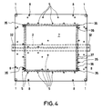
- the foundation now looks as shown in FIG. 4, with dowels 5 embedded and anchored in the foundation plate 7.
- the arrangement of the dowels 5 can also be seen from FIG.
- the dowels 5 serve, as will be explained later, for screwing on the formwork walls to create the house walls.
- the dowels on the template have already been aligned and attached so that the formwork walls, which are provided with corresponding holes, are screwed on can.
- on the outer edge of the foundation plate 7 further dowels 8 are inserted, to which, as will be explained later, lifting platforms 26 can be attached.
- Fig. 4 it can also be seen how the wire cages 35 are embedded in the foundation for installation. The arrangement of the wire cages 35 depends not least on where the doors and windows are provided in the later walls. In Fig. 4, the wire cages 35 are arranged circumferentially on the floor and vertically upwards in the corners.
- the wire cages 35 can also be used as reinforcement without cables being pulled through.
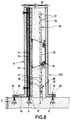
- 8 shows a horizontally arranged wire cage 35 in section and a vertically arranged wire cage 35 in broken lines.
- One longitudinal side of the wire cage 35 is essentially open and allows access to the inside of the wire cage.
- the open longitudinal wall 36 has transverse rungs 37 extending transversely to the longitudinal direction, which are arranged opposite one another, end freely and each only extend to the longitudinal center of the wire cage 35. In this way, a line can be inserted through the open side 36 of the wire cage without the risk of it emerging from this side.
- the formwork walls 9 and 10 are erected.
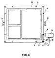
- the formwork walls 9 for the room walls are combined into so-called room formwork 11. What is hidden behind it is clear from Fig. 5.
- the outer formwork walls 9 consist of formwork elements 12 and a die 13, on which a molded skin apron made of rubber or the like is glued, in which the negative shape of the future facade is molded. While several formwork elements 12 are required when formwork is formatted on the outside of a building, the die 13 runs through an entire side of the building, as does the molded skin 14. In this way, interruptions in the design of the facade are avoided.
- the matrix can also be shorter than the full length of one side of the building.
- Both the formwork elements 12 and the formwork walls 9 forming the space formwork 11 each have an outwardly directed fastening flange 15 or 16 on their lower edge.
- Insert pins 17 are provided on the lower edge of the dies 13. These insertion pins 17 have a smaller diameter than the dowels 5 cast in the foundation 7, so that the dies 13 can be moved slightly transversely to their plane. Should it be necessary for the dies to be able to be displaced further than the play between dowels and insertion pins, it is expedient for the insertion pins to be kept displaceably in a slot in the die, by a spring or by a piece of elastic band one of the die sides can be pressed. Thus, the matrices can be moved by the amount of their thickness in addition to the play between the insertion pin and dowel.
- the fastening flange 16 of the formwork walls 10 forming the formwork 11 is provided with through holes 20, through which fastening screws 21 can be screwed into the dowels 5 embedded in the foundation plate 7, in order to fasten the space formwork 11 to the foundation plate 7.
- the spacer rods 22 are hung on the upper ends of the formwork, after which the formwork itself is already.
- the outer formwork elements 12 are set up and screwed to the die.
- the anchoring piece 19 and the set screw 18 are inserted into the outer dowels 5 screwed so that it exerts pressure against the lower mounting flange 15 of the formwork elements 12, which prevents the formwork elements from escaping to the outside.
- the formwork set up with the desired concrete e.g. B. lightweight concrete, foam concrete or gas concrete can be poured.
- the size of the foundation plate 7, seen in outline, is larger than the outline of the outer walls of the building to be constructed.
- a base 25 remains outside the outer walls.
- the aforementioned dowels 8 for fastening the lifting platforms 26 also shown in FIG. 5 are provided in the area of this base 25 and have extension arms 27 and 28 with which the base 29 of the lifting platform is already fastened to 2 dowels 8 embedded in the foundation plate 7 can.
- the length of the cantilever arms 27 and 28 is determined by the distance between the dowels 8 and the base 29. However, the length of the cantilever arms 27 and 28 will already be taken into account when the dowels 8 are attached using the template 3.
- the base 29 at a corner of the foundation e.g. B. can find a further attachment point in the alignment tube 1, in the event that the lifting platform 26 is to be attached to a corner, a further attachment point is to be provided for attaching the lifting platform on one side, which allows moments of introduction into the foundation 7.
- the fastening rail 2 already described above is provided, the two ends of which protrude from the foundation plate 7.
- the base 29 is screwed firmly to one end 31 of the mounting rail 2, so that the Fastening rail can absorb part of the moment load.
- the base 29 of the lifting platform 26 is in turn intercepted by the two extension arms 27 and 28, which are fastened to the dowels 8 arranged on the side.
- the lifting platform 26 can also be designed as a concrete distributor arm at the same time, in order to fill the formwork spaces with concrete. There are already such concrete distributor arms on which a work basket is attached.
- the formwork can be removed, for which purpose the room formwork 11 can also be divided in the usual way.
- the ceiling can be installed in the usual way as a finished ceiling.
- the template can also be used to insert two additional dowels for each formwork element into the foundation plate, into which one can then be conical Centering pins screwed in, which engage in corresponding recesses in the formwork elements.
Landscapes
- Engineering & Computer Science (AREA)
- Architecture (AREA)
- Mechanical Engineering (AREA)
- Civil Engineering (AREA)
- Structural Engineering (AREA)
- Forms Removed On Construction Sites Or Auxiliary Members Thereof (AREA)
- Building Environments (AREA)
- Supports Or Holders For Household Use (AREA)
- Time Recorders, Dirve Recorders, Access Control (AREA)
- Foundations (AREA)
Claims (13)
- Équipement pour bâtir une maison d'habitation ou une maison de vacances, avec lequel on fabrique les murs de la maison après la fabrication d' une fondation en coulant du béton, béton léger ou béton mousse dans des espaces crées par des parois de coffrages, avec des éléments de coffrages singuliers en forme de tables et des éléments d' ancrage pour la fixation des coffrages aux fondations caractérisées par le fait que l' équipement possède des chevilles d'ancrage (5) pour la pose dans les fondations encore molles (7), un gabarit (3) pour l'alignement et la fixation de toutes les chevilles d'ancrage (5) et des vis de fixation (6) qui correspondent aux chevilles d'ancrage (5), et qu'au moins une partie des éléments de coffrage (10) portent en leur partie inférieure des collerettes (16) en angle de 90 degrés par rapport à la paroi de coffrage, dans lesquelles sont prévus des trous (20) à travers lesquels on visse des vis de fixation (21) dans les chevilles d'ancrage (5).
- Équipement d'après la revendication 1, caractérisé, par le fait que les chevilles à vis d'ancrage sont fixables (5) au gabarit à l'aide de boulons de fixation (6).
- Équipement d' après la revendication 1 ou 2, caractérisé, par le fait qu'une autre partie des éléments de coffrage (12) présentent également, à leur bords inférieurs, une collerette d'encastrement fixée rectangulairement (15), qui enclenche des vis de serrage horizontales (18) qui viennent ensuite s'appuyer en l'état dans le coffrage monté aux éléments d'ancrage (19) fixés dans la dalle de fondation (7) et avec lesquelles on règle la distance entre le coffrage extérieur (9) et le coffrage intérieur correspondant (10).
- Équipement selon la revendication 3, caractérisé, par le fait que pour les coffrages extérieurs (9) qui décorent la façade est prévue une matrice (14) p.ex. de caoutchouc fixé sur un support plat (13), qui est soutenue par des éléments de coffrages (12) quand elle est montée.
- Équipement selon la revendication 4, caractérisé, par le fait que les mesures de la superficie du support de la matrice (13) sont diffèrent des mesures des éléments de coffrage (12) qui soutiennent le support de la matrice (13).
- Équipement selon une des revendications de 4 à 5, caractérisé, par le fait que le support-matrice (13) porte à son bord inférieur des goujons indiquants (17) tournés vers le bas qui s' adaptent au jeu des chevilles introduites (5) dans la fondation (7).
- Équipement, selon une des revendications de 1 à 6, caractérisé, par le fait qu'aux bords supérieurs des éléments de coffrage vis-a-vis, des (10, 12) des barres d'espacement réglables liantes (22) sont installées.
- Équipement selon une des revendications de 1 à 7, caractérisé par le fait que l' équipement comprend un rail (2) à poser dans le béton de la fondation (7) de telle façon qu'au moins l'un de ses bouts dépasse le plan de la dalle des fondations (7) et qu' à cet point du rail (2) on prévoit des points de fixation (31) pour un échafaudage ou une nacelle (26).
- Équipement selon une des revendications de 1 à 8, caractérisé, par le fait que l' équipement comprend, par la suite, des tuyaux d'alignement (1) qui seront fixés avec la construction de la fondation (7) à ses coins, et qu'ensuite aux coins du gabarit (3) soient fixés les goujons d'alignement (4) correspondants.
- Équipement selon une des revendications de 1 à 9, caractérisé, par le fait que le gabarit est assemblé par plusieurs treillis soudés.
- Équipement selon une des revendications, caractérisé, par le fait que l' équipement comprend des supports d'installation (35) en forme de cages de fil métalliques allongés et qu'ils sont fixables dans le béton encore mou de la dalle de fondations (7) à l'aide du gabarit (3).
- L'Équipement, selon une des revendications, se caractérisé par le fait que les cages de fil (35) portent sur l'une des parois longitudinales des échelons de travers intercalés qui terminent librement (37) et qu'en outre cette paroi de cage est ouverte (36).
- Équipement selon la revendication 12, caractérisé, par le fait que les échelons de travers (37) vont seulement environ jusqu' au milieu longitudinal de la paroi de la cage (36).
Applications Claiming Priority (2)
| Application Number | Priority Date | Filing Date | Title |
|---|---|---|---|
| DE4031405 | 1990-10-04 | ||
| DE4031405A DE4031405A1 (de) | 1990-10-04 | 1990-10-04 | Verfahren zum erstellen eines wohn- oder ferienhauses |
Publications (2)
| Publication Number | Publication Date |
|---|---|
| EP0480295A1 EP0480295A1 (fr) | 1992-04-15 |
| EP0480295B1 true EP0480295B1 (fr) | 1995-05-03 |
Family
ID=6415577
Family Applications (1)
| Application Number | Title | Priority Date | Filing Date |
|---|---|---|---|
| EP91116804A Expired - Lifetime EP0480295B1 (fr) | 1990-10-04 | 1991-10-01 | Ensemble pour la construction d'une maison d'habitation ou de vacances |
Country Status (3)
| Country | Link |
|---|---|
| EP (1) | EP0480295B1 (fr) |
| AT (1) | ATE122122T1 (fr) |
| DE (2) | DE4031405A1 (fr) |
Families Citing this family (2)
| Publication number | Priority date | Publication date | Assignee | Title |
|---|---|---|---|---|
| WO2009074626A1 (fr) * | 2007-12-11 | 2009-06-18 | Inventio Ag | Procédé de fixation d'un ascenseur à un bâtiment |
| CN106801482B (zh) * | 2017-02-13 | 2019-02-15 | 山东送变电工程公司 | 一种换流站防火墙施工工艺 |
Family Cites Families (10)
| Publication number | Priority date | Publication date | Assignee | Title |
|---|---|---|---|---|
| BE550666A (fr) * | ||||
| BE511396A (fr) * | ||||
| CH293955A (fr) * | 1951-07-07 | 1953-10-31 | Ind De L Aluminium Sa | Procédé de construction d'une baraque et gabarit pour la mise en oeuvre de ce procédé. |
| FR1365323A (fr) * | 1963-03-20 | 1964-07-03 | Revêtement élastique pour coffrage ou moulage | |
| FR1589090A (fr) * | 1968-07-19 | 1970-03-23 | ||
| CH559292A5 (fr) * | 1972-09-29 | 1975-02-28 | Fresa Ets | |
| US3897050A (en) * | 1973-07-20 | 1975-07-29 | Richard E Maloblocki | Stub setting fixture |
| FR2503225A1 (fr) * | 1981-04-02 | 1982-10-08 | Roy Contancin Rene | Gabarit de pose pour coulage et scellement de differents systemes de liaison et/ou d'ancrage dans les formes ou dalles beton ou autres |
| US4412407A (en) * | 1981-06-15 | 1983-11-01 | Samuel T. Melfi | Mounting arrangement for guard rail post |
| CH671442A5 (fr) * | 1986-12-08 | 1989-08-31 | Domotec Ag |
-
1990
- 1990-10-04 DE DE4031405A patent/DE4031405A1/de not_active Withdrawn
-
1991
- 1991-10-01 AT AT91116804T patent/ATE122122T1/de not_active IP Right Cessation
- 1991-10-01 DE DE59105375T patent/DE59105375D1/de not_active Expired - Fee Related
- 1991-10-01 EP EP91116804A patent/EP0480295B1/fr not_active Expired - Lifetime
Also Published As
| Publication number | Publication date |
|---|---|
| ATE122122T1 (de) | 1995-05-15 |
| DE59105375D1 (de) | 1995-06-08 |
| DE4031405A1 (de) | 1992-04-09 |
| EP0480295A1 (fr) | 1992-04-15 |
Similar Documents
| Publication | Publication Date | Title |
|---|---|---|
| DE3140287A1 (de) | "vorrichtung zur herstellung geschosshoher betonwaende" | |
| WO2008092664A2 (fr) | Élément de construction | |
| DE102004004883B4 (de) | Deckenschalungs-Paneel und System-Deckenschalung | |
| DE3824387C2 (fr) | ||
| EP0164330B1 (fr) | Plancher en béton armé | |
| EP0927796A1 (fr) | Panneau et système de coffrage | |
| EP0350525B1 (fr) | Procédé pour la réalisation de murs de constructions et système de coffrage | |
| CH701411A1 (de) | Schalung und Verfahren zum Aufbau einer Schalung. | |
| DE19525082A1 (de) | Wandelement für Hochbauten und Verfahren zu seiner Herstellung | |
| EP0480295B1 (fr) | Ensemble pour la construction d'une maison d'habitation ou de vacances | |
| DE3036539A1 (de) | Vorgefertigtes mauerstein-wandelement zur vollmontage von haeusern | |
| DE10007450A1 (de) | Montageträgersystem sowie Verfahren zur Befestigung eines Fertigbauteils an einem Gebäudeteil unter Verwendung des Montageträgersystems | |
| DE19928757C2 (de) | Montageträgersystem und Verfahren zur Montage eines Fertigbauteils an einem Gebäudeteil | |
| WO2014020009A1 (fr) | Dispositif de fabrication d'une cellule préfabriquée dans une construction monolithique | |
| EP0515724A1 (fr) | Méthode et module préfabriqué pour la construction d'édifices et des bâtiments | |
| DE29923649U1 (de) | Fertighaussystem | |
| DE29509938U1 (de) | Schalstütze | |
| AT412359B (de) | Schalung | |
| DE1434673C3 (de) | Transformatorenstation aus übereinandergestellten vorgefertigten Betonplatten und Eckteilen | |
| DE19724393A1 (de) | Wandstützenbefestigung | |
| DE3925591A1 (de) | Bausatz fuer die erstellung eines balkons | |
| AT400465B (de) | Schalung und verfahren zum giessen eines behälters aus beton | |
| DE2648935A1 (de) | Aus wenigstens einer bauplatte bestehende montagewand | |
| DE2636168A1 (de) | Verfahren und vorrichtung zum erstellen von bauwerken | |
| EP0645501A1 (fr) | Méthode pour la production de modules préfabriqués pour la construction de bâtiments et module préfabriqué |
Legal Events
| Date | Code | Title | Description |
|---|---|---|---|
| PUAI | Public reference made under article 153(3) epc to a published international application that has entered the european phase |
Free format text: ORIGINAL CODE: 0009012 |
|
| AK | Designated contracting states |
Kind code of ref document: A1 Designated state(s): AT BE CH DE DK ES FR GB IT LI NL |
|
| 17P | Request for examination filed |
Effective date: 19921014 |
|
| RAP1 | Party data changed (applicant data changed or rights of an application transferred) |
Owner name: KLAUS SCHUMANN |
|
| RIN1 | Information on inventor provided before grant (corrected) |
Inventor name: KLAUS SCHUMANN |
|
| 17Q | First examination report despatched |
Effective date: 19940228 |
|
| ITF | It: translation for a ep patent filed | ||
| GRAA | (expected) grant |
Free format text: ORIGINAL CODE: 0009210 |
|
| AK | Designated contracting states |
Kind code of ref document: B1 Designated state(s): AT BE CH DE DK ES FR GB IT LI NL |
|
| PG25 | Lapsed in a contracting state [announced via postgrant information from national office to epo] |
Ref country code: NL Free format text: LAPSE BECAUSE OF NON-PAYMENT OF DUE FEES Effective date: 19950503 Ref country code: ES Free format text: THE PATENT HAS BEEN ANNULLED BY A DECISION OF A NATIONAL AUTHORITY Effective date: 19950503 Ref country code: DK Effective date: 19950503 Ref country code: BE Effective date: 19950503 |
|
| REF | Corresponds to: |
Ref document number: 122122 Country of ref document: AT Date of ref document: 19950515 Kind code of ref document: T |
|
| REF | Corresponds to: |
Ref document number: 59105375 Country of ref document: DE Date of ref document: 19950608 |
|
| GBT | Gb: translation of ep patent filed (gb section 77(6)(a)/1977) |
Effective date: 19950612 |
|
| ET | Fr: translation filed | ||
| NLV1 | Nl: lapsed or annulled due to failure to fulfill the requirements of art. 29p and 29m of the patents act | ||
| PLBE | No opposition filed within time limit |
Free format text: ORIGINAL CODE: 0009261 |
|
| STAA | Information on the status of an ep patent application or granted ep patent |
Free format text: STATUS: NO OPPOSITION FILED WITHIN TIME LIMIT |
|
| 26N | No opposition filed | ||
| PGFP | Annual fee paid to national office [announced via postgrant information from national office to epo] |
Ref country code: DE Payment date: 19960816 Year of fee payment: 6 |
|
| PGFP | Annual fee paid to national office [announced via postgrant information from national office to epo] |
Ref country code: GB Payment date: 19960920 Year of fee payment: 6 |
|
| PGFP | Annual fee paid to national office [announced via postgrant information from national office to epo] |
Ref country code: CH Payment date: 19961128 Year of fee payment: 6 |
|
| PG25 | Lapsed in a contracting state [announced via postgrant information from national office to epo] |
Ref country code: GB Free format text: LAPSE BECAUSE OF NON-PAYMENT OF DUE FEES Effective date: 19971001 |
|
| PG25 | Lapsed in a contracting state [announced via postgrant information from national office to epo] |
Ref country code: LI Free format text: LAPSE BECAUSE OF NON-PAYMENT OF DUE FEES Effective date: 19971031 Ref country code: CH Free format text: LAPSE BECAUSE OF NON-PAYMENT OF DUE FEES Effective date: 19971031 |
|
| PGFP | Annual fee paid to national office [announced via postgrant information from national office to epo] |
Ref country code: FR Payment date: 19980327 Year of fee payment: 7 |
|
| PGFP | Annual fee paid to national office [announced via postgrant information from national office to epo] |
Ref country code: AT Payment date: 19980403 Year of fee payment: 7 |
|
| GBPC | Gb: european patent ceased through non-payment of renewal fee |
Effective date: 19971001 |
|
| REG | Reference to a national code |
Ref country code: CH Ref legal event code: PL |
|
| PG25 | Lapsed in a contracting state [announced via postgrant information from national office to epo] |
Ref country code: DE Free format text: LAPSE BECAUSE OF NON-PAYMENT OF DUE FEES Effective date: 19980701 |
|
| REG | Reference to a national code |
Ref country code: FR Ref legal event code: D3 |
|
| REG | Reference to a national code |
Ref country code: FR Ref legal event code: ST |
|
| PG25 | Lapsed in a contracting state [announced via postgrant information from national office to epo] |
Ref country code: AT Free format text: LAPSE BECAUSE OF NON-PAYMENT OF DUE FEES Effective date: 19981001 |
|
| PG25 | Lapsed in a contracting state [announced via postgrant information from national office to epo] |
Ref country code: FR Free format text: LAPSE BECAUSE OF NON-PAYMENT OF DUE FEES Effective date: 19990630 |
|
| REG | Reference to a national code |
Ref country code: FR Ref legal event code: ST |
|
| PG25 | Lapsed in a contracting state [announced via postgrant information from national office to epo] |
Ref country code: IT Free format text: LAPSE BECAUSE OF NON-PAYMENT OF DUE FEES;WARNING: LAPSES OF ITALIAN PATENTS WITH EFFECTIVE DATE BEFORE 2007 MAY HAVE OCCURRED AT ANY TIME BEFORE 2007. THE CORRECT EFFECTIVE DATE MAY BE DIFFERENT FROM THE ONE RECORDED. Effective date: 20051001 |