EP0187459B1 - Aménagement pour le montage d'un corps oscillant - Google Patents
Aménagement pour le montage d'un corps oscillant Download PDFInfo
- Publication number
- EP0187459B1 EP0187459B1 EP85308464A EP85308464A EP0187459B1 EP 0187459 B1 EP0187459 B1 EP 0187459B1 EP 85308464 A EP85308464 A EP 85308464A EP 85308464 A EP85308464 A EP 85308464A EP 0187459 B1 EP0187459 B1 EP 0187459B1
- Authority
- EP
- European Patent Office
- Prior art keywords
- fluid
- mount
- assembly
- housing
- engine
- Prior art date
- Legal status (The legal status is an assumption and is not a legal conclusion. Google has not performed a legal analysis and makes no representation as to the accuracy of the status listed.)
- Expired
Links
- 239000012530 fluid Substances 0.000 claims description 61
- 238000013016 damping Methods 0.000 claims description 27
- 238000006073 displacement reaction Methods 0.000 claims description 21
- 239000007788 liquid Substances 0.000 claims description 12
- 238000002485 combustion reaction Methods 0.000 claims description 6
- 239000007791 liquid phase Substances 0.000 claims description 6
- 239000012071 phase Substances 0.000 claims description 6
- 230000005489 elastic deformation Effects 0.000 claims description 5
- 239000000463 material Substances 0.000 description 9
- 230000006835 compression Effects 0.000 description 8
- 238000007906 compression Methods 0.000 description 8
- 229920001971 elastomer Polymers 0.000 description 6
- 238000004891 communication Methods 0.000 description 5
- 239000013536 elastomeric material Substances 0.000 description 5
- 239000000806 elastomer Substances 0.000 description 4
- LYCAIKOWRPUZTN-UHFFFAOYSA-N Ethylene glycol Chemical compound OCCO LYCAIKOWRPUZTN-UHFFFAOYSA-N 0.000 description 3
- 230000002093 peripheral effect Effects 0.000 description 3
- 230000001133 acceleration Effects 0.000 description 2
- 230000000694 effects Effects 0.000 description 2
- 238000002955 isolation Methods 0.000 description 2
- 229910052751 metal Inorganic materials 0.000 description 2
- 239000002184 metal Substances 0.000 description 2
- 230000010355 oscillation Effects 0.000 description 2
- 238000005192 partition Methods 0.000 description 2
- 239000000725 suspension Substances 0.000 description 2
- 229910000838 Al alloy Inorganic materials 0.000 description 1
- OKTJSMMVPCPJKN-UHFFFAOYSA-N Carbon Chemical compound [C] OKTJSMMVPCPJKN-UHFFFAOYSA-N 0.000 description 1
- 239000004593 Epoxy Substances 0.000 description 1
- 229910000831 Steel Inorganic materials 0.000 description 1
- 239000006096 absorbing agent Substances 0.000 description 1
- 238000004873 anchoring Methods 0.000 description 1
- 230000005540 biological transmission Effects 0.000 description 1
- 230000003247 decreasing effect Effects 0.000 description 1
- 230000005284 excitation Effects 0.000 description 1
- 229910002804 graphite Inorganic materials 0.000 description 1
- 239000010439 graphite Substances 0.000 description 1
- 238000000034 method Methods 0.000 description 1
- 238000000518 rheometry Methods 0.000 description 1
- 238000007789 sealing Methods 0.000 description 1
- 230000035939 shock Effects 0.000 description 1
- 238000004513 sizing Methods 0.000 description 1
- 230000003068 static effect Effects 0.000 description 1
- 239000010959 steel Substances 0.000 description 1
- 229920003002 synthetic resin Polymers 0.000 description 1
- 239000000057 synthetic resin Substances 0.000 description 1
Images
Classifications
-
- F—MECHANICAL ENGINEERING; LIGHTING; HEATING; WEAPONS; BLASTING
- F16—ENGINEERING ELEMENTS AND UNITS; GENERAL MEASURES FOR PRODUCING AND MAINTAINING EFFECTIVE FUNCTIONING OF MACHINES OR INSTALLATIONS; THERMAL INSULATION IN GENERAL
- F16F—SPRINGS; SHOCK-ABSORBERS; MEANS FOR DAMPING VIBRATION
- F16F15/00—Suppression of vibrations in systems; Means or arrangements for avoiding or reducing out-of-balance forces, e.g. due to motion
- F16F15/02—Suppression of vibrations of non-rotating, e.g. reciprocating systems; Suppression of vibrations of rotating systems by use of members not moving with the rotating systems
- F16F15/023—Suppression of vibrations of non-rotating, e.g. reciprocating systems; Suppression of vibrations of rotating systems by use of members not moving with the rotating systems using fluid means
-
- B—PERFORMING OPERATIONS; TRANSPORTING
- B60—VEHICLES IN GENERAL
- B60K—ARRANGEMENT OR MOUNTING OF PROPULSION UNITS OR OF TRANSMISSIONS IN VEHICLES; ARRANGEMENT OR MOUNTING OF PLURAL DIVERSE PRIME-MOVERS IN VEHICLES; AUXILIARY DRIVES FOR VEHICLES; INSTRUMENTATION OR DASHBOARDS FOR VEHICLES; ARRANGEMENTS IN CONNECTION WITH COOLING, AIR INTAKE, GAS EXHAUST OR FUEL SUPPLY OF PROPULSION UNITS IN VEHICLES
- B60K5/00—Arrangement or mounting of internal-combustion or jet-propulsion units
- B60K5/12—Arrangement of engine supports
- B60K5/1208—Resilient supports
- B60K5/1216—Resilient supports characterised by the location of the supports relative to the motor or to each other
-
- F—MECHANICAL ENGINEERING; LIGHTING; HEATING; WEAPONS; BLASTING
- F16—ENGINEERING ELEMENTS AND UNITS; GENERAL MEASURES FOR PRODUCING AND MAINTAINING EFFECTIVE FUNCTIONING OF MACHINES OR INSTALLATIONS; THERMAL INSULATION IN GENERAL
- F16F—SPRINGS; SHOCK-ABSORBERS; MEANS FOR DAMPING VIBRATION
- F16F13/00—Units comprising springs of the non-fluid type as well as vibration-dampers, shock-absorbers, or fluid springs
- F16F13/04—Units comprising springs of the non-fluid type as well as vibration-dampers, shock-absorbers, or fluid springs comprising both a plastics spring and a damper, e.g. a friction damper
- F16F13/06—Units comprising springs of the non-fluid type as well as vibration-dampers, shock-absorbers, or fluid springs comprising both a plastics spring and a damper, e.g. a friction damper the damper being a fluid damper, e.g. the plastics spring not forming a part of the wall of the fluid chamber of the damper
- F16F13/08—Units comprising springs of the non-fluid type as well as vibration-dampers, shock-absorbers, or fluid springs comprising both a plastics spring and a damper, e.g. a friction damper the damper being a fluid damper, e.g. the plastics spring not forming a part of the wall of the fluid chamber of the damper the plastics spring forming at least a part of the wall of the fluid chamber of the damper
Definitions
- the present invention relates to an apparatus or assembly for mounting a vibrating body to a support structure. More specifically, the invention relates to a system comprising mounting devices adapted to mount a body or mass subject to vibrational excitations to a frame or support structure, with damping or isolation of such vibration.
- the invention is particularly suitable for use in mounting an internal combustion engine to a motor vehicle frame or body.
- An effective engine mounting device or system is needed, therefore, to damp or isolate a broad range of vibrational modes and a broad range of vibration frequencies and amplitudes.
- an internal combustion engine will produce relatively low frequency, low amplitude torque pulses during engine idle. Larger amplitude torques are generated during clutch release and rapid acceleration.
- substantially vertical vibrational modes include low amplitude, high frequency vibrations such as those generated by power train deformations and second order unbalanced inertia forces typical in four cylinder engines.
- large amplitude essentially vertical vibrations must be damped, such as those generated by large amplitude powertrain deflections and even externally caused vibrations such as those generated by vehicle tire collisions with road obstructions, potholes etc. It is an object of the present invention to provide a mounting system which provides damping or isolation substantially effective for a broad range of vibrational frequencies, amplitudes and modes.
- Patent 4,352,487 to Shtarkman wherein a shock absorber is shown to have inner and outer rigid members connected by an elastomeric shear spring and having a main fluid chamber disposed between the two rigid members in fluid communication through a restricted orifice to a second fluid chamber within the inner rigid member.
- a third chamber is provided, specifically an elastomeric bladder within the second fluid chamber, which is selectively chargeable with gas pressure for calibrating the damping characteristics of the device.
- a fourth chamber is provided, specifically an elastomeric diaphragm, which is included in the main fluid chamber to provide a selectively chargeable gas chamber.
- Another elastomeric engine mount with hydraulic damping is shown in U.S. Patent 4,161,304 to Brenner et al.
- the engine mount thereof includes an elastic peripheral wall joined with metallic end walls to form a liquid-filled main chamber and a liquid-filled auxiliary chamber.
- the two metallic end walls are rigidly connected.
- the peripheral walls function as thrust springs.
- the partition between the two liquid-filled chambers is said to be either rigid and stationary or moveable.
- An engine mount of this kind is said to be suitable to strongly damp lower frequency, high amplitude oscillations of the engine while allowing high frequency oscillations with low amplitude pass undamped.
- Early attempts were made to provide improved damping by interconnecting multiple engine mounts.
- U.S. Patent 2,038,968 to Summers an engine mount is shown in which an elastomeric peripheral wall together with rigid end walls defines a fluid-filled chamber.
- a helical spring is embedded in the elastomeric wall for reinforcement- and damping effect, while an additional damping mode is said to be provided by virtue of a conduit providing fluid communication between the fluid-filled chamber of one and another such engine mount.
- a similar mounting system is suggested in U.S. Patent 2,705,118 to Beck, wherein rigid supporting and supported members are interconnected by a body of resilient elastomer. The elastomeric body, together with the supporting member defines a fluid-filled chamber which is so designed as to expand or contract as the supported and supporting members vibrate toward and away from each other. The chambers are said to be filled with hydraulic brake fluid and it is suggested that damping of torsional vibration can be achieved by a fluid flow restrictor valve interposed in the connecting line between the liquid-filled chambers.
- U.S. Patent 1,655,204 to Stevens is directed to a vehicle suspension means employing a fluid communication line between mounting devices.
- an assembly for mounting a vibrating body to a support structure being adapted to damp vibrations transmitted from said body to said structure
- said assembly comprising a plurality of mounts each of at least two of said mounts comprising; a substantially rigid housing with a first opening through said housing and a second opening therethrough remote from said first opening, said housing being adapted to be rigidly attached to one of said body and said support structure a first deformable elastomeric body sealingly bonded to said housing to form a fluid-tight closure of said first opening of said housing a second deformable elastomeric body of higher hysteretic damping value than said first elastomeric body said second elastomeric body, being sealingly bonded to said housing to form a fluid-tight closure of said second opening of said housing, wherein said housing said first elastomeric body and said second elastomeric body together enclose an elastically expandable chamber adapted to receive fluid means for attaching said mount to the one of said body and said
- the fluid contained within the interconnected fluid chambers of the mounts comprises a gas phase and a liquid phase and the chambers are sufficiently filled with fluid and the mounts so oriented that vibration of the engine or other mounted body in normal operation causes liquid rather than gas to flow through the fluid communicating conduit.
- the vibrating body being mounted is subjected to relatively large amplitude torsional forces and displacements
- two mounts as described above are disposed in a plane substantially normal to the roll axis of the body, that is, to the axis about which the suspended body is torsionally displaced.
- the tortional displacement of the suspended body will create pressure against the first elastomeric body of one such mount, thereby reducing the size of the fluid-filled chamber within such first mount.
- the first elastomeric body of such first mount at one side of the torque axis is being forced into compression, the first elastomeric body of the mount at the opposite side of the torque axis is put in tension, such that the fluid-filled chamber of such second mount is expanded in volume.
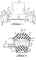
- FIG. 1 and 2 illustrate an engine mounting system comprising an engine 10 supported by a pair of engine mounts 20 and 30.
- Engine mounts 20 and 30 each comprises a rigid housing 21, 31, respectively, forming a frustro- conical sleeve opened at the upper, larger diameter end and also at the lower, smaller diameter end.
- the housings are rigidly attached to a support member 22, 32 comprising an element of a vehicle frame or body.
- Each of the engine mounts further comprises a deformable elastomeric body 23, 33 sealingly bonded to the inner surface of the housing at the larger diameter end thereof to form a fluid-tight closure of that end of the housing.
- Rigid attachment means 24, 34 are fixedly coupled to the elastomeric body 23, 33, respectively, and are adapted to fixedly engage a member 25, 35 which is rigidly integral with the engine.
- attachment means comprises a hardened metal post which is molded into the elastomeric body with a flange or washer connected to the post and embedded in the elastomeric body.
- the housing of the engine mounts each provides a port 26, 36.
- Conduit 40 is sealingly attached to each of the engine mounts at such ports and is adapted to carry the flow of fluid between one engine mount and the other.
- engine mount 20 of Figure 1 is illustrated in cross-section.
- Deformable elsatomeric body 23 is seen to be sealingly bonded at surface 50 to the frustro- conical housing 21 at the upper, larger diameter open end thereof.
- Rigid attachment means 24 is seen to comprise a metal post with an. anchoring flange 51 embedded in the elastomeric body 23.
- the attachment post is molded into the elastomer so as to be bonded thereto.
- a second elastomeric body 52 is seen to form a fluid-tight closure of the lower, smaller diameter opening of the housing. That is, the second elastomeric body 52 is continuously sealed to the housing at surface 53.
- Conduit 40 is attached to the housing at port 26.
- the two elastomeric bodies and the rigid housing cooperate to define a chamber 54, which chamber is expandable and contractable upon deformation of the two elastomeric bodies.
- the chamber 51 can expand.
- the upper elastomeric body 23 will be put into compression or tension with corresponding deformation and corresponding decrease or increase, respectively, in the volume of the chamber 54.
- the fluid-filled chamber 54 preferably comprises both liquid 55 and gas 56 and the port 26 is positioned to remain below the level of liquid within the engine mount during normal operation.
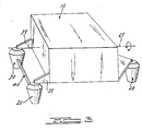
- FIG. 3 A preferred embodiment of the invention is illustrated schematically in Figure 3, wherein engine 10 is mounted by three engine mounts 20, 30, 60 to a motor vehicle support structure (not shown).
- the engine has a primary roll axis 65 and it can be seen that engine mounts 20 and 30 are positioned in a plane substantial orthogonal to the roll axis.
- one of the engine mounts 20 and 30 will be put in compression and the other will be put in tension.
- the conduit providing fluid communication between mounts is sized to permit a flow of fluid therethrough at a maximum rate in response to a large amplitude torsional displacement of the suspended body, which rate is insufficient to prevent the build-up of pressure within the fluid chamber sufficient to substantially deform the higher damped elastomeric body.
- Deformation of the higher damped elastomeric body provides effective damping of such large amplitude torsional displacements.
- Proper sizing of the conduit to provide such pressure build-up within the mount is a function of both tube length and diameter and of fluid rheology. It will be within the ability of those skilled. in the art in view of the present disclosure to select suitable conduit dimensions and fluid properties to provide such fluid build-up. It also will be within the skill of the art to employ flow restrictions such as reduced diameter orifices within the conduit to provide such pressure build-up. Also, the displacement of fluid through conduit 40 from the engine mount in compression to the engine mount in tension will further damp the torsional displacement.
- the third engine mount can be constructed as shown in Figure 2 and the fluid-filled chamber thereof can be in fluid communication with the other two engine mounts.
- the mounting assembly functions also to damp fore/aft rocking displacement of the engine according to the same method discussed above regarding damping of large amplitude torsional displacements.
- the weight of the engine is supported by the elastomeric material in compression rather than in tension.
- the lower damped elastomer that is the elastomeric body forming the closure of the larger diameter opening of the housing, in which is embedded the attachment post, preferably comprises a material such as rubber or a synthetic elastomeric material having hysteretic damping value of 6-16% of rate, where rate is defined as the newton per metre (pounds force per inch) of elastomeric deformation of the material.
- each engine mount might bear, for example, 68 kg (150 lbs), more typically 181.6-227 kg (400-500 lbs), of engine weight and have a rate of from 90.8 kg (200 lbs) per inch to 680 kg (1,500 lbs) per inch deformation, depending upon the vehicle noise, vibration and ride harshness characteristics desired. It will be understood by those skilled in the art that the rate is determined not only by the durometer of the elastomeric material, but also by its physical shape, location of attachment, and the direction of forces applied.
- the second elastomeric body that is, the one to which the engine attachment means is not directly attached, is of higher damped elastomeric material such as, for example, for use in motor vehicle engine mounts, styrenebutyl rubber or other synthetic elastomeric material having a hysteretic damping value of about 7-19% of rate.
- the fluid conduit interconnecting the engine mounts can be any of a wide variety of materials readily apparent to the skilled of the art, of which many are readily commercially available. Again, the choice of materials and dimensions will depend largely upon the application in which the mounting system is to be use. Typical for use in a motor vehicle in an engine support application would be an inside tube diameter of .63-2.5 cm (1/4 inch-1 inch).
- the damping provided by flow of fluid through the conduit can be provided by a restricted orifice inserted in the conduit.
- the tube must be of sufficient length to extend between the mounts and in a motor vehicle engine mount assembly, for example, 50.8-101.6 cms (20-40 inches) would be typical.
- the conduit can be constructed of the same materials presently used in motor vehicles for hydraulic fluid lines, for example brake lines and the like.
- the tube does not significantly expand under pressure, such that high amplitude tortional displacements of a body suspended as shown in Figure 3 would cause sufficient pressure increase within the fluid-filled chamber to deform the higher damped elastomeric body, whereby such tortional displacement would be effectively damped, as discussed above.
- the gas phase of the fluid filling the internal chamber is found to be highly effective at isolating very high frequency low amplitude vibration.
- the gas phase is intermediate the liquid phase and the lower damped elastomeric body to which the engine is attached through attachment means 24.
- the gas phase provides a non-linear spring effect with very low transmissability of high frequency low amplitude vibration. This is especially effective to isolate the passenger compartment of a motor vehicle from such vibrations as engine shake at driving speeds, for example the second order inertia forces typically generated by four cylinder engines.
- each of the engine mounts would receive substantially simultaneously a vertical (i.e. compressive) force input.
- the size of the chamber within each of the engine mounts would simultaneously be decreased and damping would be provided by elastic deformation of the lower damped elastomeric body and, more significantly, by elastic deformation of the higher damped elastomeric body.
- static support for the engine is provided essentially by the lower damped elastomeric body to (preferably in compression) which the engine is directly attached, together with the rigid housing to which the support member is directly attached.
- the lower damped elastomeric body provides essentially linear spring affect and, thus, is effective to isolate and damp high frequency low amplitude vibrations.
- lower frequency, high amplitude torsional displacements of the engine such as those generated during sudden clutch release and rapid vehicle acceleration, are effectively damped by elastic deformation of the higher damped elastomeric body in response to generation of pressure within the chamber and transmission of each pressure to the higher damped elastomeric body by the liquid phase.
- Such torsional displacement of the engine also referred to as powertrain windup, places one engine mount into compression and places a second engine mount (which with the first engine mount lies in a plane substantially orthogonal to the whole axis of the engine) in tension.
- the chamber of the first engine mount is reduced in size while that of the second is expanded.
- the fluid conduit is selected to have a diameter insufficient to simultaneously accommodate a flow of fluid from the first chamber to the second, whereby forces transmitted to the higher damped elastomeric body and the deformation thereof results in damping of the torsional engine displacement.
- the present invention has applicability as an engine support system for motor vehicles and also as a support system for like applications wherein a body subject to vibrational and other displacements must be supported and the vibrations thereof damped and isolated from the supporting structure.
Landscapes
- Engineering & Computer Science (AREA)
- General Engineering & Computer Science (AREA)
- Mechanical Engineering (AREA)
- Physics & Mathematics (AREA)
- Acoustics & Sound (AREA)
- Aviation & Aerospace Engineering (AREA)
- Chemical & Material Sciences (AREA)
- Combustion & Propulsion (AREA)
- Transportation (AREA)
- Combined Devices Of Dampers And Springs (AREA)
- Arrangement Or Mounting Of Propulsion Units For Vehicles (AREA)
Claims (10)
Applications Claiming Priority (2)
| Application Number | Priority Date | Filing Date | Title |
|---|---|---|---|
| US685690 | 1984-12-24 | ||
| US06/685,690 US4679759A (en) | 1984-12-24 | 1984-12-24 | Assembly for mounting a vibrating body |
Publications (3)
| Publication Number | Publication Date |
|---|---|
| EP0187459A2 EP0187459A2 (fr) | 1986-07-16 |
| EP0187459A3 EP0187459A3 (en) | 1987-11-11 |
| EP0187459B1 true EP0187459B1 (fr) | 1990-01-10 |
Family
ID=24753291
Family Applications (1)
| Application Number | Title | Priority Date | Filing Date |
|---|---|---|---|
| EP85308464A Expired EP0187459B1 (fr) | 1984-12-24 | 1985-11-21 | Aménagement pour le montage d'un corps oscillant |
Country Status (5)
| Country | Link |
|---|---|
| US (1) | US4679759A (fr) |
| EP (1) | EP0187459B1 (fr) |
| JP (1) | JPS61157430A (fr) |
| CA (1) | CA1246460A (fr) |
| DE (1) | DE3575281D1 (fr) |
Families Citing this family (11)
| Publication number | Priority date | Publication date | Assignee | Title |
|---|---|---|---|---|
| JPS6221304U (fr) * | 1985-07-25 | 1987-02-09 | ||
| US4784378A (en) * | 1985-11-14 | 1988-11-15 | Ford Motor Company | Vibrating body mounting assembly |
| GB8608259D0 (en) * | 1986-04-04 | 1986-05-08 | Dunlop Ltd | Anti-vibration mountings |
| US4881712A (en) * | 1988-06-21 | 1989-11-21 | General Motors Corporation | Hydraulic mount |
| EP0368607B1 (fr) * | 1988-11-07 | 1995-09-20 | Bridgestone Corporation | Appareil pour l'amortissement des vibrations pour utilisation dans le transport |
| JP3734099B2 (ja) * | 1994-06-06 | 2006-01-11 | マツダ株式会社 | 振動緩衝装置 |
| DE19717692A1 (de) * | 1997-04-26 | 1998-10-29 | Schenck Ag Carl | Feder-Massen-Schwingkraftkoppler |
| DE19838753A1 (de) * | 1998-08-26 | 2000-03-02 | Philips Corp Intellectual Pty | Flüssigkeitsgefüllter Dämpfer für ein erschütterungsempfindliches Gerät und Verfahren zu dessen Herstellung |
| KR101519285B1 (ko) * | 2014-01-22 | 2015-05-11 | 현대자동차주식회사 | 차량용 토크로드 |
| CN108278452B (zh) * | 2017-01-06 | 2020-12-22 | 青岛海尔洗衣机有限公司 | 一种家用电器用底脚及家用电器 |
| CN113653761B (zh) * | 2021-08-17 | 2023-02-24 | 淄博职业学院 | 发动机液压悬置系统及利用其实现悬置抗振的方法 |
Family Cites Families (24)
| Publication number | Priority date | Publication date | Assignee | Title |
|---|---|---|---|---|
| US1655204A (en) * | 1925-10-05 | 1928-01-03 | Stevens Products Company | Cushioning means for vehicles |
| US2038968A (en) * | 1933-12-18 | 1936-04-28 | Gen Motors Corp | Engine mounting |
| GB610958A (en) * | 1946-04-15 | 1948-10-22 | Leon Francois Thiry | Improvements in or relating to vibration-absorbing supports or mountings |
| US2705118A (en) * | 1952-01-30 | 1955-03-29 | Lord Mfg Co | Mounting system |
| DK116700A (fr) * | 1963-07-12 | |||
| FR1494326A (fr) * | 1966-07-29 | 1967-09-08 | Pied de suspension pivotant à suspension élastiquement compensée et à commande hydraulique | |
| DE2012341A1 (de) * | 1970-03-16 | 1971-10-07 | Daimler Benz AG 7000 Stuttgart | Nachgiebige Motorlagerung |
| FR2218508B1 (fr) * | 1973-02-19 | 1978-03-10 | Pineau Andre | |
| FR2255508B1 (fr) * | 1973-12-21 | 1976-10-08 | Vibrachoc Sa | |
| FR2272857B1 (fr) * | 1974-05-27 | 1978-08-04 | Peugeot & Renault | |
| US4153227A (en) * | 1975-11-28 | 1979-05-08 | Gamaunt Roger L | Fluid self-centering vibration and shock mount |
| FR2357790A1 (fr) * | 1976-04-27 | 1978-02-03 | Boge Gmbh | Support de moteur, elastique, a amortissement hydraulique, notamment pour vehicule a moteur |
| DE2727244C2 (de) * | 1976-06-30 | 1990-06-21 | Automobiles Peugeot, 75116 Paris | Gummifeder mit Flüssigkeitsfüllung |
| FR2364373A1 (fr) * | 1976-09-09 | 1978-04-07 | Peugeot | Dispositif de suspension pour machine tournante |
| DE2712641A1 (de) * | 1977-03-23 | 1978-09-28 | Phoenix Gummiwerke Ag | Elastisches lager fuer kraftfahrzeugmotore |
| DE2802896C2 (de) * | 1978-01-24 | 1982-09-23 | Audi Nsu Auto Union Ag, 7107 Neckarsulm | Gummilager mit hydraulischer Dämpfung |
| JPS55123033A (en) * | 1979-03-14 | 1980-09-22 | Mitsubishi Heavy Ind Ltd | Vibration-proof mount |
| IT1165137B (it) * | 1979-06-29 | 1987-04-22 | Gomma Antivibranti Applic | Sopporto ammortizzante per la sospensione di un corpo oscillante ad una struttura di sopporto,particolarmente per la sospensione del motore al telaio di un autoveicolo |
| US4352487A (en) * | 1980-11-18 | 1982-10-05 | Gould Inc. | Viscous spring damper |
| FR2522759A1 (fr) * | 1982-03-03 | 1983-09-09 | Hutchinson | Perfectionnements aux amortisseurs hydrauliques a membrane |
| JPS59144839A (ja) * | 1983-02-04 | 1984-08-20 | Toyota Motor Corp | 防振ゴム装置 |
| FR2542405B1 (fr) * | 1983-03-07 | 1987-07-17 | Peugeot | Dispositif de suspension d'un groupe moto-propulseur, notamment dans un vehicule automobile |
| JPS61146626A (ja) * | 1984-12-19 | 1986-07-04 | Mazda Motor Corp | パワ−ユニツトのマウンテイング装置 |
| US4706945A (en) * | 1984-12-19 | 1987-11-17 | Mazda Motor Corporation | Hydraulic mounting system for a power unit |
-
1984
- 1984-12-24 US US06/685,690 patent/US4679759A/en not_active Expired - Fee Related
-
1985
- 1985-11-21 EP EP85308464A patent/EP0187459B1/fr not_active Expired
- 1985-11-21 DE DE8585308464T patent/DE3575281D1/de not_active Expired - Lifetime
- 1985-12-06 CA CA000497104A patent/CA1246460A/fr not_active Expired
- 1985-12-19 JP JP60286865A patent/JPS61157430A/ja active Pending
Also Published As
| Publication number | Publication date |
|---|---|
| EP0187459A3 (en) | 1987-11-11 |
| DE3575281D1 (de) | 1990-02-15 |
| US4679759A (en) | 1987-07-14 |
| JPS61157430A (ja) | 1986-07-17 |
| CA1246460A (fr) | 1988-12-13 |
| EP0187459A2 (fr) | 1986-07-16 |
Similar Documents
| Publication | Publication Date | Title |
|---|---|---|
| US4784378A (en) | Vibrating body mounting assembly | |
| CA1301787C (fr) | Amortisseur en elastomere rempli de fluide | |
| US5040774A (en) | Hydraulic damping bushing | |
| JPS63265715A (ja) | サスペンション用減衰力発生装置およびそれの作動制御装置 | |
| EP0187459B1 (fr) | Aménagement pour le montage d'un corps oscillant | |
| US2582998A (en) | Fluid damped resilient mounting | |
| EP0382851B1 (fr) | Appareil de montage du type a fluide d'etancheite | |
| EP0232892A2 (fr) | Support pour le contrôle et l'isolation des vibrations | |
| US5782462A (en) | Hydraulically damped powertrain mount | |
| JPS62184251A (ja) | 油圧式ダンパ | |
| JPH0694889B2 (ja) | 流体封入式筒型マウント装置 | |
| US5855259A (en) | Viscous fluid mount | |
| JPS62261731A (ja) | 円筒型流体封入式防振支持体 | |
| US5000428A (en) | Fluid-damped strut | |
| JPH0434018B2 (fr) | ||
| JP4365004B2 (ja) | 防振装置 | |
| JP4046203B2 (ja) | 液体封入式空気ばね | |
| JPH032089B2 (fr) | ||
| JPS6332486Y2 (fr) | ||
| JPS60132145A (ja) | 防振装置 | |
| JPH09273586A (ja) | 防振装置 | |
| JPS6341322B2 (fr) | ||
| JPS6280320A (ja) | 自動車用エンジンのマウント装置 | |
| JP3071548B2 (ja) | 液体封入型防振装置 | |
| JPS61119833A (ja) | 防振支持装置 |
Legal Events
| Date | Code | Title | Description |
|---|---|---|---|
| PUAI | Public reference made under article 153(3) epc to a published international application that has entered the european phase |
Free format text: ORIGINAL CODE: 0009012 |
|
| AK | Designated contracting states |
Kind code of ref document: A2 Designated state(s): DE FR GB |
|
| PUAL | Search report despatched |
Free format text: ORIGINAL CODE: 0009013 |
|
| AK | Designated contracting states |
Kind code of ref document: A3 Designated state(s): DE FR GB |
|
| 17P | Request for examination filed |
Effective date: 19880421 |
|
| 17Q | First examination report despatched |
Effective date: 19881028 |
|
| GRAA | (expected) grant |
Free format text: ORIGINAL CODE: 0009210 |
|
| AK | Designated contracting states |
Kind code of ref document: B1 Designated state(s): DE FR GB |
|
| REF | Corresponds to: |
Ref document number: 3575281 Country of ref document: DE Date of ref document: 19900215 |
|
| ET | Fr: translation filed | ||
| PLBE | No opposition filed within time limit |
Free format text: ORIGINAL CODE: 0009261 |
|
| STAA | Information on the status of an ep patent application or granted ep patent |
Free format text: STATUS: NO OPPOSITION FILED WITHIN TIME LIMIT |
|
| REG | Reference to a national code |
Ref country code: GB Ref legal event code: 746 |
|
| 26N | No opposition filed | ||
| REG | Reference to a national code |
Ref country code: FR Ref legal event code: DL |
|
| PGFP | Annual fee paid to national office [announced via postgrant information from national office to epo] |
Ref country code: GB Payment date: 19931025 Year of fee payment: 9 |
|
| PGFP | Annual fee paid to national office [announced via postgrant information from national office to epo] |
Ref country code: DE Payment date: 19931119 Year of fee payment: 9 |
|
| PGFP | Annual fee paid to national office [announced via postgrant information from national office to epo] |
Ref country code: FR Payment date: 19931201 Year of fee payment: 9 |
|
| PG25 | Lapsed in a contracting state [announced via postgrant information from national office to epo] |
Ref country code: DE Effective date: 19941011 |
|
| PG25 | Lapsed in a contracting state [announced via postgrant information from national office to epo] |
Ref country code: GB Effective date: 19941121 |
|
| GBPC | Gb: european patent ceased through non-payment of renewal fee |
Effective date: 19941121 |
|
| PG25 | Lapsed in a contracting state [announced via postgrant information from national office to epo] |
Ref country code: FR Effective date: 19950731 |
|
| REG | Reference to a national code |
Ref country code: FR Ref legal event code: ST |