EP0187492A1 - Appareil de cuisson électrique - Google Patents
Appareil de cuisson électrique Download PDFInfo
- Publication number
- EP0187492A1 EP0187492A1 EP85309019A EP85309019A EP0187492A1 EP 0187492 A1 EP0187492 A1 EP 0187492A1 EP 85309019 A EP85309019 A EP 85309019A EP 85309019 A EP85309019 A EP 85309019A EP 0187492 A1 EP0187492 A1 EP 0187492A1
- Authority
- EP
- European Patent Office
- Prior art keywords
- heaters
- utensil
- food
- substrate
- utensil according
- Prior art date
- Legal status (The legal status is an assumption and is not a legal conclusion. Google has not performed a legal analysis and makes no representation as to the accuracy of the status listed.)
- Withdrawn
Links
- 238000010411 cooking Methods 0.000 title claims abstract description 29
- 239000000758 substrate Substances 0.000 claims abstract description 21
- 235000013305 food Nutrition 0.000 claims abstract description 13
- 238000010276 construction Methods 0.000 claims abstract description 11
- 239000004642 Polyimide Substances 0.000 claims description 5
- 239000004411 aluminium Substances 0.000 claims description 5
- XAGFODPZIPBFFR-UHFFFAOYSA-N aluminium Chemical group [Al] XAGFODPZIPBFFR-UHFFFAOYSA-N 0.000 claims description 5
- 229910052782 aluminium Inorganic materials 0.000 claims description 5
- 229920001721 polyimide Polymers 0.000 claims description 5
- BQCADISMDOOEFD-UHFFFAOYSA-N Silver Chemical compound [Ag] BQCADISMDOOEFD-UHFFFAOYSA-N 0.000 claims description 2
- 239000011248 coating agent Substances 0.000 claims description 2
- 238000000576 coating method Methods 0.000 claims description 2
- 230000000284 resting effect Effects 0.000 claims 1
- 238000010438 heat treatment Methods 0.000 abstract description 14
- 238000000926 separation method Methods 0.000 description 18
- 238000007667 floating Methods 0.000 description 13
- 239000000463 material Substances 0.000 description 11
- 235000008429 bread Nutrition 0.000 description 6
- 239000004020 conductor Substances 0.000 description 5
- 229910052751 metal Inorganic materials 0.000 description 4
- 239000002184 metal Substances 0.000 description 4
- WYTGDNHDOZPMIW-RCBQFDQVSA-N alstonine Natural products C1=CC2=C3C=CC=CC3=NC2=C2N1C[C@H]1[C@H](C)OC=C(C(=O)OC)[C@H]1C2 WYTGDNHDOZPMIW-RCBQFDQVSA-N 0.000 description 3
- 239000011521 glass Substances 0.000 description 2
- 239000012212 insulator Substances 0.000 description 2
- 230000007246 mechanism Effects 0.000 description 2
- 238000003853 Pinholing Methods 0.000 description 1
- PNEYBMLMFCGWSK-UHFFFAOYSA-N aluminium oxide Inorganic materials [O-2].[O-2].[O-2].[Al+3].[Al+3] PNEYBMLMFCGWSK-UHFFFAOYSA-N 0.000 description 1
- 238000005452 bending Methods 0.000 description 1
- 238000004140 cleaning Methods 0.000 description 1
- 230000000994 depressogenic effect Effects 0.000 description 1
- 239000000428 dust Substances 0.000 description 1
- 230000000694 effects Effects 0.000 description 1
- 239000012777 electrically insulating material Substances 0.000 description 1
- 239000012776 electronic material Substances 0.000 description 1
- 229920006351 engineering plastic Polymers 0.000 description 1
- 230000000977 initiatory effect Effects 0.000 description 1
- 239000002923 metal particle Substances 0.000 description 1
- 150000002739 metals Chemical class 0.000 description 1
- 238000000034 method Methods 0.000 description 1
- 239000000843 powder Substances 0.000 description 1
- 230000000717 retained effect Effects 0.000 description 1
- 230000000630 rising effect Effects 0.000 description 1
- 238000007650 screen-printing Methods 0.000 description 1
- 229920001169 thermoplastic Polymers 0.000 description 1
- 239000004416 thermosoftening plastic Substances 0.000 description 1
Images


Classifications
-
- A—HUMAN NECESSITIES
- A47—FURNITURE; DOMESTIC ARTICLES OR APPLIANCES; COFFEE MILLS; SPICE MILLS; SUCTION CLEANERS IN GENERAL
- A47J—KITCHEN EQUIPMENT; COFFEE MILLS; SPICE MILLS; APPARATUS FOR MAKING BEVERAGES
- A47J37/00—Baking; Roasting; Grilling; Frying
- A47J37/06—Roasters; Grills; Sandwich grills
- A47J37/0611—Roasters; Grills; Sandwich grills the food being cooked between two heating plates, e.g. waffle-irons
-
- A—HUMAN NECESSITIES
- A47—FURNITURE; DOMESTIC ARTICLES OR APPLIANCES; COFFEE MILLS; SPICE MILLS; SUCTION CLEANERS IN GENERAL
- A47J—KITCHEN EQUIPMENT; COFFEE MILLS; SPICE MILLS; APPARATUS FOR MAKING BEVERAGES
- A47J37/00—Baking; Roasting; Grilling; Frying
- A47J37/06—Roasters; Grills; Sandwich grills
- A47J37/08—Bread-toasters
- A47J37/0814—Bread-toasters with automatic bread ejection or timing means
Definitions
- the present invention relates to electric cooking utensils such as toasters and sandwich makers.
- Conventional toasters are constructed to have the material to be toasted located in a wire cage within a housing with electrical heating elements disposed between the cage and housing. Toasting of the material takes place due to radiant heat from the heating elements which must therefore produce red heat.
- Sandwich makers have a different construction in that heated plates are brought into contact with the material to be cooked but it is usual to have the plates heated by conventional electrical heating elements disposed on the other side of the plates from the material to be cooked.
- the disadvantage of this arrangement is that again the casing tends to become unacceptably hot.
- the invention provides a heated construction comprising a base substrate, at least one surface of which is electrically insulating, said surface being provided with a printed heating element.
- the heater construction In use, the heater construction is brought into intimate contact with the material to be heated.
- the advantage of this arrangement is that the temperature of the heat may be as little as 250°C and yet still produce acceptable results.
- This in turn means that a casing used to house such a heater construction can be positioned much closer to the heater than before while still being kept at a relatively low and hence safe temperature which will reduce the overall bulk of the casing.
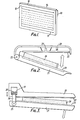
- FIG. 1 shows an embodiment of an electric heater for a cooking utensil according to the present invention.
- the heater comprises a substrate (10) with a serpentine conductor (11) provided on one major surface (12) of the substrate (10).
- Control equipment (13) is provided on the other major surface (14) of the substrate (10).
- the control equipment (13) comprises electronic feedback control not requiring any electro-mechanical components.
- the heater substrate (10) may be made from a variety of materials, such as high temperature engineering plastics materials, glasses, alumina or insulated metals, the maximum processing temperature of the substrate determining which electronic materials can subsequently be processed upon it.
- aluminium is used because of its low thermal mass (i.e. it heats quickly), cheapness and ready machinability. With aluminium, or any other metal, an insulating layer is required this may be sprayed or screen printed onto the metal.
- Thermoplastics materials such as polyimide after curing,are particularly useful as they are tolerant of mismatches in coefficients of linear expansion. To provide a compact unit it is desirable to keep the substrate thickness to a minimum however it is also important not to sacrifice mechanical strength.
- a thickness of about 1mm would be about the lowest practicable unless the mechanical strength were improved by adding a webbing on the back of the substrate.
- metallic substrates there is also the insulating layer to be considered. This must be thick enough to avoid short circuits through pinholing and dust.
- a satisfactory insulator thickness for polyimide on an aluminium substrate is about 60 pm.
- the serpentine conductor (11) of the heater in Figure l' is a heating element.
- This may be made from a variety of conductive materials deposited on the substrate by a suitable method, e.g. screen printing or writing with a robot arm.
- the type of material used is chosen to be compatible with the substrate (and insulator if applicable), on high temperature glasses commercially available thick film type materials may be used; among other possible materials are metal powders or insulants loaded with metal particles,such as polyimide loaded with silver flake.
- the thickness of the heating element is largely determined by current carrying requirements and a thickness of about 10 pm is suitable for many applications.
- the configuration of the heating element is serpentine in the embodiment shown in Figure 1 but other configurations may be used.
- By increasing the density of the element on the substrate a greater Watts density is obtained and hence a shorter cooking time.
- care must be taken not to thermally overstress the element - this could be avoided by using a feedback system from a surface mounted thermocouple or thermistor to the control electronics.
- control equipment itself need not be directly attached to the substrate (as shown in Figure 1) but may be arranged elsewhere within the cooking utensil of which the heater is a part.
- the heater may be moulded by bending and pressing into a three-dimensional shape as desired.
- Figures 2 and 3 show two basic electric cooking utensils which use heaters as shown in Figure 1.
- FIG. 2 shows a toaster having relatively movable housing parts 20 and 21 each provided with a heater 22 and 23 respectively.
- the housing parts 20 and 21 are hinged together at 25 to permit opening and closing of the housing.
- a piece of bread to be toasted is identified by the reference numeral 26.
- the heater 23 is fixed relative to its housing part whereas the heater 22 is mounted in a post 27 to be movable as indicated by the arrow A in order to ensure that when the housing parts 20,21 are closed together, the surfaces of the heaters 22,23 on which the conductors are provided will be in intimate contact with the opposite sides of the slice of bread 26 and different thicknesses of bread can be accommodated.
- heater 23 could also be movable in the same way as heater 22.
- An alternative construction would be to have an intermediate arm, one end of which is hinged at 25 and the other end of which is connected to the housing part 21. This would enable the toaster to accommodate different thicknesses of bread to be toasted without necessitating the use of "floating" heaters although such could be used with the intermediate arm construction.
- Figure 3 shows an alternative construction for a toaster.
- like reference numerals are used for like parts.
- This construction is similar in many ways to that shown in Figure 2 in as much as heaters 22,23 may be fixed or "floating". The major difference is in the way the housing parts are connected together and co-operate to accommodate the slice of bread to be toasted.
- the housing part 21 is hinged to an intermediate member 30 which is reciprocable with respect to the housing part 20 as indicated by the arrows in Figure 3.
- the member 30 forms the position rod of a piston assembly whose piston head 31 is biased by a spring 32 to the upper, closed position.
- the hinge 25 may be provided with a ratchet arrangement whereby the housing part 21 can assume and maintain any desired angular position with respect to the member 30.
- FIGs 4 and 5 show a practical embodiment of a cooking utensil which latches in a different manner from that used in the simple embodiments of Figures 2 and 3 (like reference numerals are used wherever possible).
- Figure 4 shows an upright cooking utensil using heaters in two pairs to defined two cooking areas, each pair comprising one fixed heater (23) and one floating heater (22) located in respective housing parts (21) and (20) with thermally and electrically insulating material between each heater and its housing part.
- the housing parts (20), containing floating heaters (22). are hinged to allow cleaning of the surfaces of all the heaters.
- each cooking area an ejector (50) is provided movable between a first, raised position and a second lowered (cooking) position as indicated by arrow B.
- an operating column (52) which houses a brown control (53), for setting the length of the cooking time, and an operating handle (41).
- the whole utensil is mounted by means of a base portion (54) which is attached to a detachable drip tray (55).
- a desired cooking time is set using the brown control (53), the food to be cooked, e.g. bread (26), is dropped into one or both cooking areas to rest on the ejector (50) in its raised position.
- the operating handle (41) is lowered manually, the ejector (50) is moved to its lower position and the floating heater (22) moves towards the fixed heater (23) until it is brought into intimate contact with the food to be cooked. If no food is present in the cooking area projections (37) on one housing (21) impact the opposite housing (20) on the lowering of the operating handle (41) so that contact between the facing heaters is avoided.
- projections (37) could be located on either housing whilst still achieving the some effect.
- Figure 5 shows a cross-sectional view of the cooking utensil of Figure 4 in a closed, cooking position and more clearly illustrates the working of the cooking utensil.
- the operating handle (41) is connected to a separation device (40) which has a slanting profile to its top face.
- the separation device (40) is biased towards the top of the operating column (52) by a spring (not shown).
- the floating heater (22) is biased towards the fixed heater (23) by a further spring (not shown) but its movement is restricted by the separation device (40) in two ways: firstly a lip (36) along one edge of the separation device (40) protrudes behind the floating heater (22) limiting the maximum separation of the two heaters, and secondly a cam follower (35) provided on the free surface of the floating heater (22) rests on the slanting top of the separation device (40) and is constrained to move along this profile when the separation device (40) is moved up and down.
- the separation device (40) When the operating handle (41) is manually depressed the separation device (40) is lowered and the ejector (50) is moved to its lower position.
- the floating heater (22) is gradually freed to move under the action of its bias spring and it is brought up against the food to be cooked (26).
- the separation device (40) is retained in its lowered position, electrical contact is made and current flows in the conductors (11) of each heater.
- a solenoid (45) When the current has flowed for the time set by the brown control (53) a solenoid (45) is activated which pushes the lower end (44a) of the latch (44) and disengages the latch from the notch.
- Figure 5 only shows half of the cooking utensil.
- the other pair of heaters are operated in a similar way with certain details open to variation.
- a single operating handle (41) may be used to operate one separation device (40) configured to control the separation of both sets of heaters, or alternatively, two separation devices (40) one for each pair of heaters.
- two operating handles (42) may be provided to operate two separation devices (40) one for each pair of heaters. Whichever mode is used the provision of floating heaters'(22) enables the heating elements (11) to contact the food (26) directly.
- the brown control (53) comprises electronic timing circuitry connected to the heater elements (11). and to the latch release mechanism. Although a solenoid (45) has been described as the means for initiating latch release other known mechanisms could be used.
- the drip tray (55) may be detached and a wall-mounting bracket attached to the base portion (54) of the cooking utensil for mounting the utensil in a transverse,generally horizontal plane.
- a wall-mounting bracket attached to the base portion (54) of the cooking utensil for mounting the utensil in a transverse,generally horizontal plane.
- special mountings could be used to enable the utensil to be suspended under a cabinet.
- both heaters in a pair may be floating rather than having one heater floating and one fixed within its housing part.
Landscapes
- Engineering & Computer Science (AREA)
- Food Science & Technology (AREA)
- Baking, Grill, Roasting (AREA)
- Electric Stoves And Ranges (AREA)
Applications Claiming Priority (2)
| Application Number | Priority Date | Filing Date | Title |
|---|---|---|---|
| GB8431198 | 1984-12-11 | ||
| GB848431198A GB8431198D0 (en) | 1984-12-11 | 1984-12-11 | Electric cooking utensil |
Publications (1)
| Publication Number | Publication Date |
|---|---|
| EP0187492A1 true EP0187492A1 (fr) | 1986-07-16 |
Family
ID=10570994
Family Applications (1)
| Application Number | Title | Priority Date | Filing Date |
|---|---|---|---|
| EP85309019A Withdrawn EP0187492A1 (fr) | 1984-12-11 | 1985-12-11 | Appareil de cuisson électrique |
Country Status (2)
| Country | Link |
|---|---|
| EP (1) | EP0187492A1 (fr) |
| GB (1) | GB8431198D0 (fr) |
Cited By (6)
| Publication number | Priority date | Publication date | Assignee | Title |
|---|---|---|---|---|
| WO1988005279A1 (fr) * | 1987-01-15 | 1988-07-28 | Dreamland Electrical Appliances Plc | Grille-pain electriques |
| WO1998035597A1 (fr) | 1997-02-14 | 1998-08-20 | Seb S.A. | Appareil electrique de grillage ou de rechauffage d'aliment plan |
| US7351939B2 (en) | 2004-03-19 | 2008-04-01 | Whirlpool Corporation | Toaster |
| NL2001983C (nl) * | 2008-09-12 | 2010-03-16 | Princess Household Appliances B V | Inrichting en werkwijze voor het bereiden van tosti's en dergelijke. |
| WO2010054443A1 (fr) * | 2008-11-14 | 2010-05-20 | Quick Cuisine Pty Ltd | Appareil de cuisson avec plaques non métalliques |
| GB2537408A (en) * | 2015-04-17 | 2016-10-19 | Charles Isaacson Roger | A low power, rapid toasting device |
Citations (6)
| Publication number | Priority date | Publication date | Assignee | Title |
|---|---|---|---|---|
| CH255396A (de) * | 1947-03-10 | 1948-06-30 | Maxim Ag Fabrik Fuer Thermo El | Elektrischer Brotröster. |
| US2711684A (en) * | 1953-06-25 | 1955-06-28 | William S Taylor | Combined toaster and grill |
| NL6803985A (fr) * | 1968-03-21 | 1969-09-23 | ||
| FR2069381A5 (fr) * | 1969-11-14 | 1971-09-03 | Matsushita Electric Industrial Co Ltd | |
| US3737624A (en) * | 1970-09-16 | 1973-06-05 | Progressive Products Co | Electric grill with a thin-film heating element |
| FR2221106A1 (fr) * | 1973-03-16 | 1974-10-11 | Electro Food |
-
1984
- 1984-12-11 GB GB848431198A patent/GB8431198D0/en active Pending
-
1985
- 1985-12-11 EP EP85309019A patent/EP0187492A1/fr not_active Withdrawn
Patent Citations (6)
| Publication number | Priority date | Publication date | Assignee | Title |
|---|---|---|---|---|
| CH255396A (de) * | 1947-03-10 | 1948-06-30 | Maxim Ag Fabrik Fuer Thermo El | Elektrischer Brotröster. |
| US2711684A (en) * | 1953-06-25 | 1955-06-28 | William S Taylor | Combined toaster and grill |
| NL6803985A (fr) * | 1968-03-21 | 1969-09-23 | ||
| FR2069381A5 (fr) * | 1969-11-14 | 1971-09-03 | Matsushita Electric Industrial Co Ltd | |
| US3737624A (en) * | 1970-09-16 | 1973-06-05 | Progressive Products Co | Electric grill with a thin-film heating element |
| FR2221106A1 (fr) * | 1973-03-16 | 1974-10-11 | Electro Food |
Cited By (9)
| Publication number | Priority date | Publication date | Assignee | Title |
|---|---|---|---|---|
| WO1988005279A1 (fr) * | 1987-01-15 | 1988-07-28 | Dreamland Electrical Appliances Plc | Grille-pain electriques |
| EP0276916A1 (fr) * | 1987-01-15 | 1988-08-03 | Dreamland Electrical Appliances P.L.C. | Grille-pain électrique |
| US5006690A (en) * | 1987-01-15 | 1991-04-09 | Dreamland Electrical Applicances Plc | Electric toasters |
| WO1998035597A1 (fr) | 1997-02-14 | 1998-08-20 | Seb S.A. | Appareil electrique de grillage ou de rechauffage d'aliment plan |
| US6192790B1 (en) | 1997-02-14 | 2001-02-27 | Seb S.A. | Electric appliance for grilling or heating a flat slice of food |
| US7351939B2 (en) | 2004-03-19 | 2008-04-01 | Whirlpool Corporation | Toaster |
| NL2001983C (nl) * | 2008-09-12 | 2010-03-16 | Princess Household Appliances B V | Inrichting en werkwijze voor het bereiden van tosti's en dergelijke. |
| WO2010054443A1 (fr) * | 2008-11-14 | 2010-05-20 | Quick Cuisine Pty Ltd | Appareil de cuisson avec plaques non métalliques |
| GB2537408A (en) * | 2015-04-17 | 2016-10-19 | Charles Isaacson Roger | A low power, rapid toasting device |
Also Published As
| Publication number | Publication date |
|---|---|
| GB8431198D0 (en) | 1985-01-23 |
Similar Documents
| Publication | Publication Date | Title |
|---|---|---|
| US5374807A (en) | Domestic cooking apparatus | |
| CN1146343C (zh) | 烘烤或重新加热扁平食品的电气装置 | |
| US20180328591A1 (en) | Isothermal Cooking Plate Apparatus, System, and Method of Manufacture and Use | |
| AU2305101A (en) | A toaster with transparent heater walls | |
| EP0187492A1 (fr) | Appareil de cuisson électrique | |
| CA1284893C (fr) | Grille-pain electrique | |
| US2910929A (en) | Toaster apparatus | |
| US20210251046A1 (en) | Cooking device having a modular ceramic heater | |
| RU2286031C2 (ru) | Излучающий электронагревательный элемент | |
| US2508464A (en) | Thermal timing device | |
| US2355153A (en) | Electric toaster | |
| GB2050073A (en) | Electric cooking appliance | |
| NL8902238A (nl) | Verwarmingselement en stelsel omvattende een dergelijk verwarmingselement. | |
| GB2338632A (en) | Metal sheathed planar element: Edge connector with shutter | |
| US5097751A (en) | Device for supporting the mechanical and electrical control members of a toaster an toaster comprising such a device | |
| US3707906A (en) | Two-plate griddle | |
| US3529534A (en) | Electric toaster with heat up cool down bimetal timer | |
| US2250966A (en) | Cooking apparatus | |
| US2816501A (en) | Adjustable toaster | |
| US2880665A (en) | Grill accessory for electric toasfers | |
| US2213728A (en) | Cooking apparatus | |
| RU2846606C1 (ru) | Тостер | |
| JPH0147169B2 (fr) | ||
| MXPA99007521A (en) | Electric appliance for grilling or heating a flat slice of food | |
| RU1787429C (ru) | Электронагревательный прибор дл жидкости |
Legal Events
| Date | Code | Title | Description |
|---|---|---|---|
| PUAI | Public reference made under article 153(3) epc to a published international application that has entered the european phase |
Free format text: ORIGINAL CODE: 0009012 |
|
| AK | Designated contracting states |
Kind code of ref document: A1 Designated state(s): AT BE CH DE FR GB IT LI LU NL SE |
|
| 17P | Request for examination filed |
Effective date: 19870116 |
|
| 17Q | First examination report despatched |
Effective date: 19880127 |
|
| STAA | Information on the status of an ep patent application or granted ep patent |
Free format text: STATUS: THE APPLICATION IS DEEMED TO BE WITHDRAWN |
|
| 18D | Application deemed to be withdrawn |
Effective date: 19880607 |
|
| RIN1 | Information on inventor provided before grant (corrected) |
Inventor name: BROWNE, EDWARD KEITH Inventor name: PATON, MICHAEL |