EP0187503A2 - Nachrichtensystem mit Gemeinschaftsleitung - Google Patents
Nachrichtensystem mit Gemeinschaftsleitung Download PDFInfo
- Publication number
- EP0187503A2 EP0187503A2 EP85309181A EP85309181A EP0187503A2 EP 0187503 A2 EP0187503 A2 EP 0187503A2 EP 85309181 A EP85309181 A EP 85309181A EP 85309181 A EP85309181 A EP 85309181A EP 0187503 A2 EP0187503 A2 EP 0187503A2
- Authority
- EP
- European Patent Office
- Prior art keywords
- line
- module
- data
- modules
- transmission
- Prior art date
- Legal status (The legal status is an assumption and is not a legal conclusion. Google has not performed a legal analysis and makes no representation as to the accuracy of the status listed.)
- Withdrawn
Links
Images
Classifications
-
- H—ELECTRICITY
- H04—ELECTRIC COMMUNICATION TECHNIQUE
- H04L—TRANSMISSION OF DIGITAL INFORMATION, e.g. TELEGRAPHIC COMMUNICATION
- H04L12/00—Data switching networks
- H04L12/28—Data switching networks characterised by path configuration, e.g. LAN [Local Area Networks] or WAN [Wide Area Networks]
- H04L12/40—Bus networks
- H04L12/40143—Bus networks involving priority mechanisms
-
- G—PHYSICS
- G06—COMPUTING OR CALCULATING; COUNTING
- G06F—ELECTRIC DIGITAL DATA PROCESSING
- G06F13/00—Interconnection of, or transfer of information or other signals between, memories, input/output devices or central processing units
- G06F13/14—Handling requests for interconnection or transfer
- G06F13/36—Handling requests for interconnection or transfer for access to common bus or bus system
- G06F13/368—Handling requests for interconnection or transfer for access to common bus or bus system with decentralised access control
- G06F13/372—Handling requests for interconnection or transfer for access to common bus or bus system with decentralised access control using a time-dependent priority, e.g. individually loaded time counters or time slot
-
- H—ELECTRICITY
- H04—ELECTRIC COMMUNICATION TECHNIQUE
- H04L—TRANSMISSION OF DIGITAL INFORMATION, e.g. TELEGRAPHIC COMMUNICATION
- H04L12/00—Data switching networks
- H04L12/28—Data switching networks characterised by path configuration, e.g. LAN [Local Area Networks] or WAN [Wide Area Networks]
- H04L12/40—Bus networks
- H04L12/407—Bus networks with decentralised control
- H04L12/413—Bus networks with decentralised control with random access, e.g. carrier-sense multiple-access with collision detection [CSMA-CD]
- H04L12/4135—Bus networks with decentralised control with random access, e.g. carrier-sense multiple-access with collision detection [CSMA-CD] using bit-wise arbitration
Definitions
- This invention relates to a communication system having a shared line for coupling data between two or more modules, each module comprising a transmitter (TXD) and a receiver (RXD), and means responsive to the receiver for preventing the start of transmission of data onto the line until after a delay has elapsed since the last received pulse.
- TXD transmitter
- RXD receiver
- the terminals include computers of all sizes, workstations, file servers and word processors. Also, the size of the network is variable. A single line typically allows communication between terminals in a building, and communication links can connect lines between cities.
- a well known local area network is the Ethernet system which comprises a single shared line between terminals. When a collision is detected, both terminals back off for a random time interval and try again. All terminals have equal priority.
- the Ethernet system can be adapted to enable communication between processors in a large hardware system with distributed processing.
- An example is a large copier or duplicator with five or more processors, each dedicated to a different function.
- a difference between this adaptation and the usual local area network is that the communication system for controlling hardware must allow for operation in real time. It has been determined that if each terminal is wired into a central clock, and if it is a statistical certainty that the communication bandwidth is high enough for all messages to arrive at the destinations before they are required, regardless of collisions, then the system will be suitable for real time operation.
- This system can be justified for a large hardware terminal such as a large high-speed duplicator, but not for a small terminal such as a typewriter, which cannot absorb its complexity and cost.
- the present invention is intended to provide such a system, and provides a communication system of the kind specified which is characterised by means for prioritising the modules so as to resolve collisions in favour of the module with the highest priority.
- the shared line communication network described herein connects four modules or processors within an electronic typewriter with a single communication line, but does not have a system clock wired to each module. This saves the cost of the additional wiring and also reduces radiated radio frequency noise problems.
- the module with the higher priority continues to transmit in most cases, and the one with the lower priority backs off until the line is clear again.
- One advantage of this procedure is that there are fewer retransmissions, resulting in the system communicating a greater amount of data for a given bandwidth.
- the priority algorithm is easily implemented, and can be explained as follows: Assume 1) a system with four processors having the following binary descriptions, 000, 100, 110 and 111, 2) that two terminals start to transmit at the same time, 3) that the first transmitted word is the binary terminal designation number, 4) that the shared line is driven by collector ORing so that a low from any transmitter pulls the entire line down, 5 ) that a low signal is defined as "0" bit, and 6) that each terminal detects a collision by comparing the transmitted signal to the signal on the shared line. Now, if terminal 000 and 100 start to transmit, terminal 100 will see the collision (it transmits 100 and receives 000) and will back off while terminal 000 will not see the collision (it transmits 000 and receives 000) and will continue to transmit. In this way, the system can operate in real time, and the function that has the higher priority transmits its entire message first.
- a problem with the priority system in this invention is that the colliding transmissions must start at the same time. Unsynchronized station designation bits will not allow the priority mechanism to operate properly, all modules will see a collision, and no module will secure the line. In a hypothetical system where clock lines are wired to all processors, synchronization could be more easily accomplished. In this invention, the same result is accomplished without the clock lines by each module monitoring the shared line, and delaying the start of the next transmission by a predetermined time period from the end of the last transmission. In this way, all contending transmissions will start at the same time. There is also the delay caused by the transmission time of a message on the shared line between distant modules to consider in large systems but in a small terminal such as a typewriter, the transmission time is insignificant.
- This invention therefore provides low cost, real time, shared line communication for a small hardware system having distributed processing.
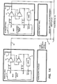
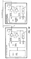
- the described embodiment of this invenion is a typewriter having the general organization as shown in Figure 1.
- Each of four main modules, printer, keyboard, text processor and communications, is controlled by a processor which is coupled to the shared line 10 through an 8051 communication controller 11.
- the transmission from the controller 11 is supplied through line driver 12 to the shared line 10, an, open collector line with a pull-up resistor 13 for each driver 12.
- a collision is defined as a non-equality between the transmitted data at the controller transmitted data pin TXD and the data received data pin RXD.
- All received pulses are coupled to the logic block 15 which is basically a counter that is constantly reset to zero by the received pulses.
- all four logic 15 counters start to count a number of clock pulses, which are generated locally in each module, and at a predetermined count, an output is sent to each controller 11 on the INTO line to enable the next transmission.
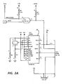
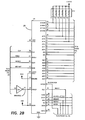
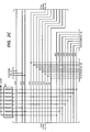
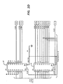
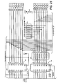
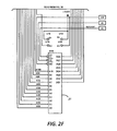
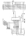
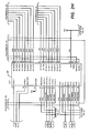
- This circuitry is shown in more detail in Figure 2.
- the 8088 processor 20 shares a 2016 memory device 21 (2K by 8 bits) with the communication controller 20 for local storage.
- the address lines are labelled AOB through A10B at the memory device 21 and ADO through AD7 and A8 through A10 at the processor 20.
- Latches 22 hold address information output from the processor 20, and buffer 23 controls data direction and flow.
- the clock for the processor is generated by clock generator 24, an 8284 device.
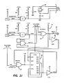
- the priority logic is controlled by gates 25-30.
- the transmitted data from the controller 32 pin TXD is tied to an open collector noninverting line driver OR gate 25, the output of gate 25, an MC3446A device or equivalent, being connected to the shared line 10.
- Fifty ohm pull-up resistor 31 is tied to plus five volts. This transmission is coupled back to OR gate 26 and to the receiver pin, RXD, of the controller 32.
- a collision is defined as a non-equality between the data on the TXD and RXD pins.
- a processor secures the shared line, it will continue to transmit information until it finishes its transmission. During this time, all other processors wait. At the end of transmission, all other processors that are waiting to transmit wait a predetermined amount of time after the last transmitted pulse before transmitting. This delay is timed by device 30, an LS393 device, which is implemented as a counter. Clock pulses arriving on the ALE line clock the counter 30.
- the first stage overflows at output pin QA8 and this overflow pulse is used to clock the second stage.
- the final overflow output at QB8 is then used as the delayed pulse.
- This pulse is output through inverter 28 to enable the controller 32 to start transmitting, and also disables additional pulses coupled through gate 27.
- it is coupled through gate 29 to clear both halves of the counter 30, resetting it to zero. Then, at the end of transmission the count resumes, delaying the next transmission by the predetermined amount.
- the actual delay in the described system is 64 microseconds. As described above, this time delay must be accurate so that all stations start transmitting at the same time.
- the crystal controlled 8051 device is suitable for this purpose.
- the built-in delay is the major difference between this system and the prior art.
- random delays are used to make it less likely for two stations to begin a transmission at the same time.
- the various stations are forced to start at the same time. This allows the assignment of priorities between processors, and is feasible because of the small number of processors involved.
- the system designer may decide to design two or more processors with the same priority. For example, if the two processor designators were 101 and 110, and if the entire designation is received before the determination of a collision is decided, then both processors will see the collison and back off. This is useful where the priority between the two processors is a function of other factors. In this case, the software internal to each processor can determine the momentary priority, the lower priority processor waiting a longer time, controlled by the software, before attempting another transmission.
- the shared line may be extended to connect to them.
- the single wire allows attachment with a minimum of cost and rf radiation.
- a typical transmission starts with the processor 20 loading data into memory 21 and then signaling the controller that the data is available for transmission. Then, the controller 32 will access the data, eight bits in parallel, on lines ADO-7 through buffer 23, and transmit it serially on the TXD line. Similarly, received serial data is received at the controller 32 on the RXD line and is converted into eight bit parallel data for storage.
- a frame is one serial transmission of a specific length, all frames are 11 bits consisting of 1 start bit, 1 stop bit, 8 data bits, and 1 bit which is used to interrupt all devices when set. This bit is called transmitted bit 8.
- a device address frame is a specific number which results in a predetermined data pattern when transmitted.
- the address assigned to a particular device will determine the priority or degree of difficulty that the device will have in securing the line.
- a source/destination frame is the second byte sent in any transmission which defines where the data is to be coming from and where it is to be going. This frame will have transmitted bit 8 set to signal a SRC/DES frame. Transmitted bit 8 being set will interrupt all devices provided they have their SM2 bits set for automatic wake up.
- a line/link is the single wire which all devices are using to communicate.
- a packet is a number of frames which are sent sequentially with a minimum duration from frame to frame of less than the duration of two frames.
- a packet comprises, in this order, a device address frame, a source/destination frame, an unlimited number of data or command frames which are defined by the user, and one or two end frames containing a check sum.
Landscapes
- Engineering & Computer Science (AREA)
- Theoretical Computer Science (AREA)
- Computer Networks & Wireless Communication (AREA)
- Signal Processing (AREA)
- Physics & Mathematics (AREA)
- General Engineering & Computer Science (AREA)
- General Physics & Mathematics (AREA)
- Small-Scale Networks (AREA)
Applications Claiming Priority (2)
| Application Number | Priority Date | Filing Date | Title |
|---|---|---|---|
| US68810284A | 1984-12-31 | 1984-12-31 | |
| US688102 | 1984-12-31 |
Publications (2)
| Publication Number | Publication Date |
|---|---|
| EP0187503A2 true EP0187503A2 (de) | 1986-07-16 |
| EP0187503A3 EP0187503A3 (de) | 1987-08-19 |
Family
ID=24763124
Family Applications (1)
| Application Number | Title | Priority Date | Filing Date |
|---|---|---|---|
| EP85309181A Withdrawn EP0187503A3 (de) | 1984-12-31 | 1985-12-17 | Nachrichtensystem mit Gemeinschaftsleitung |
Country Status (2)
| Country | Link |
|---|---|
| EP (1) | EP0187503A3 (de) |
| JP (1) | JPS61222345A (de) |
Cited By (3)
| Publication number | Priority date | Publication date | Assignee | Title |
|---|---|---|---|---|
| EP0382469A3 (de) * | 1989-02-06 | 1991-08-21 | Compaq Computer Corporation | Buszugriffsarbitrierung in digitalen Rechnern |
| EP0568314A3 (de) * | 1992-04-28 | 1994-11-09 | Matsushita Electric Industrial Co Ltd | Dezentrales Datenverarbeitungssternnetz und dazugehörige Konzentrator und Endgeräte. |
| EP0756402A1 (de) * | 1995-07-25 | 1997-01-29 | Cho, Jin-young | Verteiltes serielles Arbitrierungssystem |
Families Citing this family (2)
| Publication number | Priority date | Publication date | Assignee | Title |
|---|---|---|---|---|
| FI81225C (fi) * | 1988-09-30 | 1990-09-10 | Kone Oy | Foerfarande och anordning foer att saenda meddelande i binaerform i en serietrafikbuss. |
| JPH07101880B2 (ja) * | 1990-11-28 | 1995-11-01 | 三菱電機株式会社 | 周辺装置の共用化方式 |
Family Cites Families (4)
| Publication number | Priority date | Publication date | Assignee | Title |
|---|---|---|---|---|
| EP0064818A1 (de) * | 1981-04-20 | 1982-11-17 | Pitney Bowes, Inc. | Verfahren zum Vermeiden von Datenkollision |
| US4642630A (en) * | 1982-12-28 | 1987-02-10 | At&T Bell Laboratories | Method and apparatus for bus contention resolution |
| DE3248446A1 (de) * | 1982-12-29 | 1984-07-05 | Philips Kommunikations Industrie AG, 8500 Nürnberg | Verfahren zum zugreifen auf eine erste ader einer mehradrigen leitung |
| US4598285A (en) * | 1983-05-27 | 1986-07-01 | At&T Bell Laboratories | Scheme for reducing transmission delay following collision of transmissions in communication networks |
-
1985
- 1985-12-17 EP EP85309181A patent/EP0187503A3/de not_active Withdrawn
- 1985-12-24 JP JP29180885A patent/JPS61222345A/ja active Pending
Cited By (4)
| Publication number | Priority date | Publication date | Assignee | Title |
|---|---|---|---|---|
| EP0382469A3 (de) * | 1989-02-06 | 1991-08-21 | Compaq Computer Corporation | Buszugriffsarbitrierung in digitalen Rechnern |
| EP0568314A3 (de) * | 1992-04-28 | 1994-11-09 | Matsushita Electric Industrial Co Ltd | Dezentrales Datenverarbeitungssternnetz und dazugehörige Konzentrator und Endgeräte. |
| US5592623A (en) * | 1992-04-28 | 1997-01-07 | Matsushita Electric Industrial Co., Ltd. | System for a distributed wireless star network with terminal devices and a concentrator including start bits and ORing logic for resolving transmission contention |
| EP0756402A1 (de) * | 1995-07-25 | 1997-01-29 | Cho, Jin-young | Verteiltes serielles Arbitrierungssystem |
Also Published As
| Publication number | Publication date |
|---|---|
| EP0187503A3 (de) | 1987-08-19 |
| JPS61222345A (ja) | 1986-10-02 |
Similar Documents
| Publication | Publication Date | Title |
|---|---|---|
| US5561771A (en) | System for transmitting data between systems using selected subsets of plural interconnecting bus lines and including selection of a compatible transmission speed | |
| US6823412B2 (en) | System and method for arbitration of a plurality of processing modules | |
| CA1317031C (en) | Hierarchial arbitration system | |
| US4560985A (en) | Dual-count, round-robin distributed arbitration technique for serial buses | |
| US4590467A (en) | Local area network interface controller | |
| CA1140231A (en) | Bus collision avoidance system for distributed network data processing communications system | |
| US4799052A (en) | Method for communicating data on a communication network by token passing | |
| US4550402A (en) | Data communication system | |
| EP0422914B1 (de) | Station zu Station Vollduplexkommunikation bei Kommunikationsnetzwerken | |
| US4760571A (en) | Ring network for communication between one chip processors | |
| US4516122A (en) | Communication system with collision detection and forced collision | |
| US4470110A (en) | System for distributed priority arbitration among several processing units competing for access to a common data channel | |
| US4803681A (en) | Data transmission control system | |
| US4561092A (en) | Method and apparatus for data communications over local area and small area networks | |
| US4593281A (en) | Local area network interframe delay controller | |
| US4564838A (en) | Data communication network and method of communication | |
| US5422885A (en) | Contention free local area network | |
| EP0060517A1 (de) | System zum Vielfachzugriff von Endgeräten an eine digitale Fernsprechleitung | |
| US4596012A (en) | Master controller succession system for bus control access for data-communications local area networks | |
| JPH07134690A (ja) | マルチマスタシリアルバスシステム | |
| EP0064818A1 (de) | Verfahren zum Vermeiden von Datenkollision | |
| US6219353B1 (en) | Message hub | |
| EP0187503A2 (de) | Nachrichtensystem mit Gemeinschaftsleitung | |
| EP0785651A1 (de) | Empfängerteilung für Zwischenverstärker mit "demand priority" Zugriffsverfahren | |
| US20010019579A1 (en) | Infinitely expandable ethernet network repeater unit |
Legal Events
| Date | Code | Title | Description |
|---|---|---|---|
| PUAI | Public reference made under article 153(3) epc to a published international application that has entered the european phase |
Free format text: ORIGINAL CODE: 0009012 |
|
| AK | Designated contracting states |
Kind code of ref document: A2 Designated state(s): BE DE FR GB IT SE |
|
| PUAL | Search report despatched |
Free format text: ORIGINAL CODE: 0009013 |
|
| AK | Designated contracting states |
Kind code of ref document: A3 Designated state(s): BE DE FR GB IT SE |
|
| STAA | Information on the status of an ep patent application or granted ep patent |
Free format text: STATUS: THE APPLICATION HAS BEEN WITHDRAWN |
|
| 18W | Application withdrawn |
Withdrawal date: 19870827 |
|
| RIN1 | Information on inventor provided before grant (corrected) |
Inventor name: BALLARD, TERRY L. |