EP0187511A2 - Automatischer Anrufbeantworter für Fernsprecher - Google Patents
Automatischer Anrufbeantworter für Fernsprecher Download PDFInfo
- Publication number
- EP0187511A2 EP0187511A2 EP85309325A EP85309325A EP0187511A2 EP 0187511 A2 EP0187511 A2 EP 0187511A2 EP 85309325 A EP85309325 A EP 85309325A EP 85309325 A EP85309325 A EP 85309325A EP 0187511 A2 EP0187511 A2 EP 0187511A2
- Authority
- EP
- European Patent Office
- Prior art keywords
- auto
- recorded
- magnetic tape
- playback
- detecting means
- Prior art date
- Legal status (The legal status is an assumption and is not a legal conclusion. Google has not performed a legal analysis and makes no representation as to the accuracy of the status listed.)
- Withdrawn
Links
Images




Classifications
-
- H—ELECTRICITY
- H04—ELECTRIC COMMUNICATION TECHNIQUE
- H04M—TELEPHONIC COMMUNICATION
- H04M1/00—Substation equipment, e.g. for use by subscribers
- H04M1/64—Automatic arrangements for answering calls; Automatic arrangements for recording messages for absent subscribers; Arrangements for recording conversations
- H04M1/65—Recording arrangements for recording a message from the calling party
- H04M1/6515—Recording arrangements for recording a message from the calling party using magnetic tape
Definitions
- This invention relates to auto telephone answering apparatus for recording an incoming message (ICM) while the called telephone is unattended.
- ICM incoming message
- a recorded outgoing message stating that the called party is out, and that an ICM will be recorded is played back and sent to the calling party upon reception of a call, and an ICM is then recorded.
- a known auto telephone answering apparatus of this type has a selector switch tor selecting an auto answer mode or a listen mode. When a user or subscriber is leaving the phone unattended, the selector switch is set in the auto answer mode.
- US patent specification US-A-4 421 954 describes an auto telephone answering apparatus using a one mechanical deck (1MD) system in which a single tape can sequentially record an OGM and a plurality of ICMs.
- an OGM is first played to make certain that the OGM is properly recorded in a predetermined tape format.
- the tape is rewound to the beginning of the OGM and is ready for an incoming call.
- the OGM is played and sent to the calling party, and an ICM is recorded on the tape.
- recording of the ICM has been completed, the tape is rewound to the beginning ot the OGM and is ready for the next incoming call.
- the OGM When the second incoming call is received, the OGM is played and sent to the calling party. Then, the tape is fast forwarded to skip the tirst ICM, and the second ICM is recorded atter the first ICM. After the second ICM has been recorded, the tape is again rewound to the beginning of the OGM and is ready for the next call. The same operation is repeated automatically to record sequentially a plurality of ICMs.
- the user sets the switch to select the listen mode and depresses a play button.
- the ICMs are played sequentially starting from the first recorded ICM.
- a known auto telephone answering apparatus When the ICMs are being played back, a known auto telephone answering apparatus normally goes into a stop mode when all the ICMs have been played back or when ICM playback is manually interrupted to permit the user to attend to some other urgent business. If the user again leaves the telephone unattended while the apparatus is in the stop mode, he may forget to set the switch in the auto answer mode, thus resulting in the failure to record subsequently received ICMs.
- the auto answer mode is cancelled when a tape cassette is inserted or ejected with the apparatus in its auto answer mode.
- the user When a plurality of tapes with different OGMs are prepared and used for different purposes, the user must set the switch to establish the auto answer mode each time he replaces one tape with another, thus inconveniencing the user.
- the user since only the beginning of an OGM need be checked to determine the OGM content, the user often interrupts OGM playback before completion thereof. To do this, the user depresses the stop button or sets the selector switch in the auto answer mode. If the stop button is depressed for that purpose, the selector switch must be thereafter set in the auto answer mode to ensure that incoming messages will be recorded. However, the user often forgets to do this, resulting in the failure to record ICMs.
- an auto telephone answering apparatus for playing an outgoing message recorded on a magnetic tape and sending the outgoing message to a calling party and for recording an incoming message from the calling party on said magnetic tape, the apparatus comprising:
- control means for rendering operative the auto answer setting means is also responsive to loading of a magnetic tape cassette into an operative position in the apparatus, to interruption of the playback of the recorded outgoing message, or to interruption of the playback of a recorded incoming message.
- embodiments of the invention can provide an auto telephone answering apparatus which can be automatically set in an auto answer mode a predetermined time after all ICMs have been played back, or automatically set in an auto answer mode a predetermined time after ICM playback has been interrupted, or automatically set in an auto answer mode a predetermined time after a cassette has been inserted, or automatically set in an auto answer mode a predetermined time after OGM playback has been interrupted.
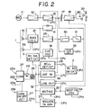
- Figure 1 generally shows an input/output circuit and recording circuit of the embodiment of auto telephone answering apparatus according to this invention and which are connected to a telephone set
- Figure 3 shows a peripheral circuit system associated with a CPU 10 of a microcomputer by which all operations of the apparatus are automatically controlled.
- an OGM signal from a microphone 11 is supplied to a record/playback head 15 through a microphone amplifier 12, a record amplifier 13 under the control of the CPU 10 and an equalizer 14, so that the OGM signal is recorded by the head 15 on the tape 1.
- a cue signal from a cue signal oscillator 16 under the control of the CPU 10 is supplied to the head 15 for recording on the tape 1.
- the cue signal oscillator 16 is also operated under the control of the CPU 10 at a predetermined time during ICM recording.
- the OGM signal is supplied to a loudspeaker 19 through a potentiometer 17 and a main amplifier 18, and thus may be monitored.
- an earphone plug (not shown) is inserted in an earphone jack 20.
- a bias oscillator 21 is operated under the control of the CPU 10 to supply a bias current to the head 15, and at the same time, to supply an erasure current from the bias oscillator 21 to an erase head 38.
- a beep tone signal is supplied by a beep tone oscillator 34 to the head 15 through a muting circuit 35, a line input circuit 36, the record amplifier 13, and the equalizer 14, and is thereby recorded on the tape 1 under the control of the CPU 10 over the record amplifier 13, the beep tone oscillator 34, the muting circuit 35 and the line input circuit 36.
- a connector 24 is connected to terminals 22a and 22b of a telephone set and terminals 23a and 23b of a main wire.
- a line transformer 25 is connected to the connector 24 through a DC loop relay 26 which, as hereinafter shown, is energised under the control of the CPU 10.
- An on/off-hook detector 27 is connected to the terminal 23b to detect whether the receiver is on or off the hook, and the detection output thereof is applied to the CPU 10.
- the reproduced signal is supplied from the head 15 through a preamplifier 29 to a high-pass filter 30 which eliminates the cue signal.
- the reproduced OGM is then sent through an equalizer 31 to the loudspeaker 19 through the amplifier 18, and at the same time, is sent through a line output circuit 32 under the control of the CPU 10 to the calling party by way of the line transformer 25 and the telephone lines.
- the reproduced OGM signal is also supplied from the preamplifier 29 to a cue signal detector 33.
- a cue detection signal from the cue signal detector 33 is supplied to the CPU 10.
- an ICM signal from the calling party is supplied from the line transformer 25 to the line input circuit 36 under the control of the CPU 10.
- the ICM signal is supplied to the head 15 from the line input circuit 36 through the record amplifier 13 and the equalizer 14, and is recorded by the head 15 on the tape 1. If the duration of the ICM exceeds 60 seconds, a beep tone is generated by the beep tone oscillator 34 under the control of the CPU 10 and the latter also automatically interrupts recording. Mute and beep tone portions are formed on the tape 1 by operating the erase head 38 and the beep tone oscillator 34, respectively, at times determined by the CPU 10.
- the auto telephone answering apparatus can also be remote controlled.
- a remote controller number is supplied from a remote control number switch circuit 2 to the CPU 10.
- the remote control signal sent from the remote controller through the telephone lines is detected by a remote control signal detector 3.
- the CPU 10 receives a +B power source voltage when a switch 40, which detects the presence of a tape cassette with its recording safety tab intact, and the connector 24 are both ON.
- a reel shaft rotation detector 42 detects stopping of the rotation of a reel shaft 41 when the tape 1 is rewound to a tape top point N0.
- the rotation detector 42 also detects the number of reel revolutions when the tape 1 is driven from the tape top point N 0 .
- the CPU 10 also receives command signals from a mode selection switch assembly 64 in addition to command signals from the remote control number switch circuit 2, the remote control signal detecting circuit 3, the hook on/off detector 27, the ringing signal detector 28 and the cue signal detector 33.
- the CPU 10 is further shown to control a plunger or solenoid energising or driver circuit 43 for operating a solenoid 51 for effecting forward drive of the tape 1, for example, by pressing a pinch roller (not shown) against a rotated capstan with the tape 1 therebetween, and also for operating a cue signal plunger or solenoid 52.
- a driver circuit 44 for a capstan motor 53 Also controlled by the CPU 10 are a driver circuit 44 for a capstan motor 53, a driver circuit 45 for a motor 54 which drives reels on which the tape 1 is wound, an energising or driver circuit 46 for the relay 26, a display energising or driver circuit 47 for a display device 55 which, for example, can display a recording number, and LED driver circuits 48,49,50,60 and 61 for energising LEDs 56,57,58,59 and 62 by which various operating states of the apparatus are visually indicated. Finally, a reset circuit 63 is provided for resetting the CPU 10 after each application of power to the apparatus.
- FIG. 1 shows a format of a magnetic tape 1 on which an OGM and a plurality of ICMs have been recorded
- detection of the start points of the OGM and of the ICMs and other necessary tape position detection is effected in the auto telephone answering apparatus by detecting numbers of reel revolutions by means of the rotation detector 42, and by comparing the detected values with reel revolution number data previously stored in the CPU 10.
- Reference symbols N 0 , N 1 and N 2 in the following description and the drawings denote tape points defined by respective reel revolution numbers.
- a 0.5 sec. mute portion P 1 and a 0.5 sec. cue portion P 2 are formed in succession beginning at point N 3 after the leader tape L.
- An OGM of up to 60 seconds is recorded together with a cue signal, for example, having a frequency of 30 Hz. in a portion P3 of the tape 1.
- a 4 sec. mute portion and a 0.2 sec. beep tone are recorded in portions P 4 and P 5 , respectively, of the tape 1 after the OGM.
- a first ICM (1) of up to 60 seconds is recorded in a tape portion P from a point N 7 to a point N S .
- the first ICM (1) is initially recorded together with a cue signal, for example, having a frequency of 30 Hz, for the first three seconds, as in portion P 6a .
- a one-second mute portion P 7 and a 0.2 sec. beep tone portion P 8 are recorded in sequence after the first ICM (1) in the portion P 6 , and then a second ICM (2) is recorded in a portion P from a point N 9 .
- a third and subsequent ICMs up to at least 20 ICMs are recorded, and each ICM is separated, by a mute portion and a beep tone portion, as at the points P 7 and P 8 , from the preceding recorded ICM.
- OGM playback for checking whether the OGM has been recorded in the predetermined OGM format.
- the apparatus is thus set in the auto answer mode or ready state for receiving an incoming call.
- the CPU 10 stores values of ICM end points N 8 ,N 10 , ... from the rotation detector 42 each time ICM recording is performed.
- the reel revolution number can be detected and compared by the CPU 10 with the number of ICMs recorded on the tape 1 to cue the recording start position.
- Control signals from the CPU 10 are supplied to components of the circuit shown in Figures 2 and 3, and the CPU 10 receives command signals from certain of those components so as to cause suitably timed operation of the apparatus as noted in steps (1) to (27) above.
- the above-described auto telephone answering apparatus has the following functional features incorporated into the program of the CPU 10:
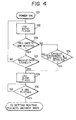
- step 101 when power is applied to the apparatus in step 101, the LED 62 is made to flash rapidly in step 102 so long as a cassette has not been operatively positioned or inserted in the apparatus.
- step 103 the presence or absence of the recording safety tab on the cassette housing is detected in step 103, for example, by means of the switch 40. If a recording safety tab is not detected in the step 103, it is presumed therefrom that information already recorded on the tape 1 is not to be erased and, therefore, the originally inserted cassette is exchanged or replaced by a new cassette in step 104 which also involves detection of a recording safety tab on the newly inserted cassette.
- step 104 is repeated, that is, the cassette is repeatedly exchanged until a cassette with a recording safety tab thereon is detected.
- the rapid flashing of the LED 62 is changed to the slow flashing thereof in step 105.
- a predetermined period of time for example, 5 seconds
- step 107 it is determined whether back-up data is stored in step 107. If the existence of back-up data in the memory is detected in the step 107, the routine proceeds to the step 105 in which the LED 62 is made to flash slowly and, thereafter, after 5 seconds have elapsed, as determined in the step 106, the program automatically proceeds to the setting routine for the auto answer mode. However, if the existence of back-up data in the memory is not detected in step 107, rapid flashing of the LED 62 will continue and the apparatus does not proceed to the setting routine for the auto answer mode.
- the apparatus can only proceed to the setting routine for the auto answer mode if back-up data was stored in the memory, thereby to prevent inadvertent erasing of ICMs recorded on the tape 1 prior to the power failure due to accidental setting of the auto answer mode.
- OGM test playback is initiated in accordance with a suitable routine (not shown). If the format of the OGM is found to be abnormal, as earlier described, the movement of the tape 1 in the OGM test playback is halted and the LED 62 is made to flash rapidly for indicating an OGM error to the user. The foregoing condition continues until the cassette in which an OGM with an abnormal format has been recorded is replaced by a cassette in which an OGM has been properly recorded. So long as the cassette inserted in the apparatus contains an OGM with an improper or abnormal format, no answer will be given by the automatic telephone answering apparatus even when a ringing signal is received.
- a "caution tone” is produced to alert the user to the fact that the inserted cassette has an OGM with an improper format recorded therein.
- the tape 1 is rewound and the cue signal in the tape portion P 2 at the beginning of the OGM is detected, and the apparatus proceeds to the setting routine for the auto answer mode.
- step 202 it is determined, in step 202, whether a "playback/listen again" push-button of the mode selector switch assembly 64 has been depressed. If it is determined that the "playback/listen again" push-button has been depressed, the apparatus proceeds to a playback routine in which ICMs, if any, recorded on the tape cassette are played back with such ICMs being protected from erasure. Furthermore, if the "playback/listen again" push-button is depressed during ICM playback, then the reproduction or playback of the ICMs is repeated.
- step 203 it is determined in step 203 whether the cue portion P at the beginning of the OGM can be detected as an indication that the OGM format is normal and further that the tape 1 is properly positioned. If the OGM cue is not detected in the step 203, a timer associated with the reel rotation detector 42 for determining the positions along the tape 1 is reset in step 204, and the setting routine is returned to the step 202 with one of the LEDs 56 to 59 being energised to indicate that the apparatus cannot be set in its auto answer mode.
- the setting routine for the auto answer mode proceeds to the step 205 in which it is determined whether the cassette residing in the apparatus has its recording safety tab thereon. If the recording tab is not detected in the step 205, thereby indicating that the cassette contains recorded information that is not to be erased, the routine recycles to the step 204. However, if a recording safety tab is detected in the step 205, then it is confirmed in step 206 that back-up data is stored in the memory. If stored back-up data is not detected in the step 206, the routine returns to the step 204.
- step 207 if stored back-up data is detected in the step 206, it is next determined in step 207 if there is a bell input, that is, if the telephone with which the answering apparatus is associated is then being called. If a bell input is detected in step 207, the routine progresses to step 208 which determines the lapse of 5 'seconds, and then causes the energising of the LED 58 in step 209. Such energising of the LED 58 in the step 209 indicates to the user that the apparatus has attained its auto answer mode, that is, the apparatus is in a ready state for receiving an incoming call.
- step 210 it is determined in step 210 whether there is checking of the OGM, that is, whether there is test playback of the OGM by a suitable routine (not shown). If checking of the OGM is not detected in the step 210, the routine proceeds directly to the step 208 for establishing the auto answer mode upon the lapse of 5 seconds. However, if the step 210 detects OGM checking or test playback, the operation proceeds to a step 211 in which it is determined whether one or more ICMs are recorded. If no ICMs are recorded, the routine proceeds directly to the step 208 for establishing the auto answer mode upon the lapse of 5 seconds.
- step 211 determines that one or more ICMs are recorded, then the lapse of a predetermined longer time, for example 30 seconds, is determined in step 212 prior to progressing to the step 209 for energising the LED 58 and establishing the auto answer mode.
- the 30 second period of time established in the step 212 is selected to provide an adequate opportunity for the user of the apparatus to protect, that is, to prevent erasure, of the ICMs.
- the CPU 10 constantly monitors the end positions of all ICMs by means of the reel revolution numbers corresponding to points N 8 ,N lo , etc., and the respective cue signals. When the tape 1 reaches the end of the last ICM recorded thereon, the CPU 10 generates a mechanical stop signal to halt the forward driving of the tape 1. If the user depresses the "playback/listen again" push-button while the apparatus is thus in its stop mode, the tape 1 is rewound and may be played back from a position corresponding to the moment when the user released the "playback/listen again” push-button. It the user does not actuate any of the push-buttons of the mode selector switch assembly 64 after ICM playback has halted, the apparatus automatically proceeds to the setting routine for the auto answer mode described with reference to Figure 5.
- this tact is detected in the step 211 in Figure 5 with the result that the auto answer mode is established only atter the lapse of 30 seconds, as provided in the step 212, tor ensuring that the user has an opportunity to protect the recorded ICMs.
- the apparatus is in its ready state for the next incoming call.
- the OGM When an incoming call is received and the detector 28 detects two rings, the OGM is played back or reproduced and transmitted to the calling party and, thereafter, a new ICM is recorded either from the starting portion of the ICM (1), in the case where the previous ICMs are not protected, or after the last ot the previously recorded ICMs, in the case where such previously recorded ICMs are protected.
- FIG. 7 shows a program routine for ICM playback
- the actuation of the "stop" push-button of the mode selector switch assembly 64 tor halting the ICM playback before the end of the last recorded ICM is detected in step 402.
- the tape drive mechanism of the apparatus is halted in step 403, and, thereafter, the maintenance in the memory of data concerning the ICMs, for example, the numbers corresponding to the points N 7 to N ll , is ensured in step 404 before returning to the setting routine for the auto answer mode.
- step 402 It actuation of the "stop" push-button is not detected in the step 402, the routine proceeds to step 405 which detects the end point, for example, that indicated at the point N 10 in Figure 1, of the last recorded ICM.
- step 405 the routine proceeds to step 406 which determines whether the "playback/listen again" push-button is actuated within 30 seconds following the completion of the playback of the last ICM. It the "playback/listen again" push-button is actuated within that period of 30 seconds, the apparatus is changed-over to its rewind mode in step 407 and, at the completion of the rewinding of the tape 1, the ICM playback is again initiated in the step 401.
- step 406 If actuation of the "playback/listen again" push-button within 30 seconds is not detected in the step 406, then the drive mechanism for the tape 1 is stopped in step 408 and the LED 59 which was energised during ICM playback is de-energised or turned off immediately prior to the return of the apparatus to the setting routine for the auto answer mode, described with reference to Figure 5.
- the auto answer mode is automatically set predetermined times after a cassette has been inserted in the apparatus, after OGM playback has been interrupted, after all recorded ICMs have been played back, and after ICM playback has been interrupted.
Landscapes
- Engineering & Computer Science (AREA)
- Signal Processing (AREA)
- Indexing, Searching, Synchronizing, And The Amount Of Synchronization Travel Of Record Carriers (AREA)
- Mobile Radio Communication Systems (AREA)
- Telephonic Communication Services (AREA)
Applications Claiming Priority (2)
| Application Number | Priority Date | Filing Date | Title |
|---|---|---|---|
| JP59279323A JPS61157138A (ja) | 1984-12-28 | 1984-12-28 | 留守番電話装置 |
| JP279323/84 | 1984-12-28 |
Publications (2)
| Publication Number | Publication Date |
|---|---|
| EP0187511A2 true EP0187511A2 (de) | 1986-07-16 |
| EP0187511A3 EP0187511A3 (de) | 1989-01-18 |
Family
ID=17609568
Family Applications (1)
| Application Number | Title | Priority Date | Filing Date |
|---|---|---|---|
| EP85309325A Withdrawn EP0187511A3 (de) | 1984-12-28 | 1985-12-20 | Automatischer Anrufbeantworter für Fernsprecher |
Country Status (4)
| Country | Link |
|---|---|
| US (1) | US5014297A (de) |
| EP (1) | EP0187511A3 (de) |
| JP (1) | JPS61157138A (de) |
| CA (1) | CA1244980A (de) |
Families Citing this family (5)
| Publication number | Priority date | Publication date | Assignee | Title |
|---|---|---|---|---|
| JPS63278452A (ja) * | 1987-05-11 | 1988-11-16 | Tamura Electric Works Ltd | 留守番電話装置 |
| US5442685A (en) * | 1990-06-13 | 1995-08-15 | Matsushita Electric Industrial Co., Ltd. | Automatic telephone answering apparatus including conversion recording mode |
| US5278896A (en) * | 1990-06-13 | 1994-01-11 | Matsushita Electric Industrial Co., Ltd. | Automatic answering telephone apparatus |
| US5546452A (en) * | 1995-03-02 | 1996-08-13 | Geotel Communications Corp. | Communications system using a central controller to control at least one network and agent system |
| GB2509323B (en) | 2012-12-28 | 2015-01-07 | Glide Talk Ltd | Reduced latency server-mediated audio-video communication |
Family Cites Families (8)
| Publication number | Priority date | Publication date | Assignee | Title |
|---|---|---|---|---|
| JPS5225052B2 (de) * | 1972-02-21 | 1977-07-05 | ||
| US3947642A (en) * | 1974-08-26 | 1976-03-30 | B.S.R. (U.S.A.) Ltd. | Telephone answering system and apparatus |
| US3991274A (en) * | 1975-03-28 | 1976-11-09 | Darwood James R | Telephone answering system with one responsive circuit for remote playback control |
| JPS52124804A (en) * | 1976-04-12 | 1977-10-20 | Matsushita Electric Ind Co Ltd | Automatic answering telephone set |
| JPS56158561A (en) * | 1980-05-12 | 1981-12-07 | Sony Corp | Automatic answering telephone set |
| JPS573461A (en) * | 1980-06-09 | 1982-01-08 | Sony Corp | Automatic answering telephone device |
| DE3022677A1 (de) * | 1980-06-18 | 1982-01-14 | Licentia Patent-Verwaltungs-Gmbh, 6000 Frankfurt | Ueberlastungsschutzschalter fuer leitungsverstaerker |
| US4596901A (en) * | 1984-02-13 | 1986-06-24 | T.A.D. Avanti, Inc. | Telephone answering machine with remote control capabilities |
-
1984
- 1984-12-28 JP JP59279323A patent/JPS61157138A/ja active Pending
-
1985
- 1985-12-17 US US06/809,776 patent/US5014297A/en not_active Expired - Lifetime
- 1985-12-19 CA CA000498154A patent/CA1244980A/en not_active Expired
- 1985-12-20 EP EP85309325A patent/EP0187511A3/de not_active Withdrawn
Also Published As
| Publication number | Publication date |
|---|---|
| CA1244980A (en) | 1988-11-15 |
| JPS61157138A (ja) | 1986-07-16 |
| EP0187511A3 (de) | 1989-01-18 |
| US5014297A (en) | 1991-05-07 |
Similar Documents
| Publication | Publication Date | Title |
|---|---|---|
| US4608459A (en) | Telephone answering device | |
| US4436959A (en) | Automatic telephone answering device | |
| US4421954A (en) | Automatic telephone answering and message recording device | |
| US5014297A (en) | Telephone answering device with automatic return to incoming message mode | |
| US4654485A (en) | Single frequency remote control of telephone answering device accomplishes several functions dependent on the present state of the device | |
| US4343039A (en) | Dictation-transcription method and system | |
| US4829556A (en) | Telephone answering device having telephone answering and conversation recording modes of operation | |
| JPS6337991B2 (de) | ||
| GB2032225A (en) | Control Device in an Automatic Telephone Answering Apparatus | |
| US4734929A (en) | Telephone answering machines for collect call | |
| US4813068A (en) | Easily operable automatic telephone answering/recording apparatus | |
| JPS6124855B2 (de) | ||
| KR940010853B1 (ko) | 자동전화 응답장치 | |
| KR930001828B1 (ko) | 부재중 녹음 전화장치 | |
| JP2576438B2 (ja) | 留守番電話装置 | |
| US4829557A (en) | Telephone answering device having outgoing message pause timer function | |
| JPH0669191B2 (ja) | 留守番電話装置 | |
| JPS61157141A (ja) | 留守番電話装置 | |
| JP2576437B2 (ja) | 留守番電話装置 | |
| JPS6259946B2 (de) | ||
| JPH0669192B2 (ja) | 留守番電話装置 | |
| JP2502538B2 (ja) | 留守番電話装置 | |
| JPS6124854B2 (de) | ||
| JPS60250760A (ja) | 機能電話機 | |
| JPS6089158A (ja) | 留守番電話装置のモ−ドチエツク方式 |
Legal Events
| Date | Code | Title | Description |
|---|---|---|---|
| PUAI | Public reference made under article 153(3) epc to a published international application that has entered the european phase |
Free format text: ORIGINAL CODE: 0009012 |
|
| AK | Designated contracting states |
Kind code of ref document: A2 Designated state(s): DE FR GB |
|
| PUAL | Search report despatched |
Free format text: ORIGINAL CODE: 0009013 |
|
| AK | Designated contracting states |
Kind code of ref document: A3 Designated state(s): DE FR GB |
|
| 17P | Request for examination filed |
Effective date: 19890523 |
|
| STAA | Information on the status of an ep patent application or granted ep patent |
Free format text: STATUS: THE APPLICATION HAS BEEN WITHDRAWN |
|
| 18W | Application withdrawn |
Withdrawal date: 19910306 |
|
| R18W | Application withdrawn (corrected) |
Effective date: 19910306 |
|
| RIN1 | Information on inventor provided before grant (corrected) |
Inventor name: MORITA, AKIROC/O PATENTS DIVISION Inventor name: NAKANO, YOSHITOMOC/O PATENTS DIVISION |