EP0187534B1 - Appareil de traitement du signal couleur avec une fonction d'interpolation de signal pour utilisation dans un duplicateur en couleurs - Google Patents
Appareil de traitement du signal couleur avec une fonction d'interpolation de signal pour utilisation dans un duplicateur en couleurs Download PDFInfo
- Publication number
- EP0187534B1 EP0187534B1 EP85309505A EP85309505A EP0187534B1 EP 0187534 B1 EP0187534 B1 EP 0187534B1 EP 85309505 A EP85309505 A EP 85309505A EP 85309505 A EP85309505 A EP 85309505A EP 0187534 B1 EP0187534 B1 EP 0187534B1
- Authority
- EP
- European Patent Office
- Prior art keywords
- color
- picture element
- signals
- light receiving
- picture
- Prior art date
- Legal status (The legal status is an assumption and is not a legal conclusion. Google has not performed a legal analysis and makes no representation as to the accuracy of the status listed.)
- Expired
Links
- 238000012545 processing Methods 0.000 title claims description 21
- 238000000926 separation method Methods 0.000 claims description 16
- 238000010586 diagram Methods 0.000 description 9
- 238000000034 method Methods 0.000 description 7
- 238000006243 chemical reaction Methods 0.000 description 6
- 230000014509 gene expression Effects 0.000 description 6
- 239000011159 matrix material Substances 0.000 description 6
- 230000006866 deterioration Effects 0.000 description 3
- 238000009826 distribution Methods 0.000 description 3
- 230000003595 spectral effect Effects 0.000 description 3
- 238000001311 chemical methods and process Methods 0.000 description 2
- 239000003086 colorant Substances 0.000 description 2
- 238000005516 engineering process Methods 0.000 description 2
- 239000011521 glass Substances 0.000 description 2
- 239000000976 ink Substances 0.000 description 2
- 238000012546 transfer Methods 0.000 description 2
- 238000012935 Averaging Methods 0.000 description 1
- 101000860173 Myxococcus xanthus C-factor Proteins 0.000 description 1
- 230000002411 adverse Effects 0.000 description 1
- 230000005540 biological transmission Effects 0.000 description 1
- 230000001934 delay Effects 0.000 description 1
- 238000011161 development Methods 0.000 description 1
- 238000005286 illumination Methods 0.000 description 1
- 230000035945 sensitivity Effects 0.000 description 1
- 239000000126 substance Substances 0.000 description 1
Images



Classifications
-
- H—ELECTRICITY
- H04—ELECTRIC COMMUNICATION TECHNIQUE
- H04N—PICTORIAL COMMUNICATION, e.g. TELEVISION
- H04N1/00—Scanning, transmission or reproduction of documents or the like, e.g. facsimile transmission; Details thereof
- H04N1/46—Colour picture communication systems
- H04N1/56—Processing of colour picture signals
-
- H—ELECTRICITY
- H04—ELECTRIC COMMUNICATION TECHNIQUE
- H04N—PICTORIAL COMMUNICATION, e.g. TELEVISION
- H04N1/00—Scanning, transmission or reproduction of documents or the like, e.g. facsimile transmission; Details thereof
- H04N1/46—Colour picture communication systems
- H04N1/56—Processing of colour picture signals
- H04N1/58—Edge or detail enhancement; Noise or error suppression, e.g. colour misregistration correction
Definitions
- color copying technology involves two categories: an electronic color picture reproduction system and a chemical color picture reproduction system.
- the former uses, for color picture reproduction, electrical signals obtained by optically scanning a color original picture.
- the latter employs a chemical process, such as development process for color picture reproduction.
- the electrical color picture reproduction system is, at the present stage of technology, liable to be adversely affected with noises and is low in resolution, although having attractive advantages of no need for chemical process and of possibility of various processings for the color image reproduction.
- the color signals corresponding to one pixel are color signals corresponding to separate points on the color picture.
- an influence imposed by the spatially dividing type image sensor on a reproduced color picture is negligibly small due to deterioration of high frequency components caused by a distributed index rod lens array.
- picture portions where luminance greatly varies, such as edges in a black character picture however, unnegligible errors occur in signals during color signal processing. Such errors also occur in a chromatic edge portion and a dot picture (color picture printed by printing machines). This cause deterioration in color reproducbility and picture quality of a reproduced color picture.
- An object of this invention is to provide an improved color picture signal processing apparatus.
- Another object of the present invention is to provide a color signal processing apparatus for use in a color copier using a spatially dividing type image sensor, which can reduce errors which occur in color signals during color signal processing due to the structure of the image sensor.
- the color signal processing apparatus is characterized in that it comprises an interpolation operation circuit means which is connected to receive the color signals from the color light receiving element array for interpolating color signals of adjacent picture elements arrayed in one line in order to reduce errors in color signals which are caused by the positional differences between the three or more light receiving elements defining each picture element.
- the normalized picture information signals are applied to a brightness and color-difference separation circuit 23 for forming a brightness signal I and color-difference signals C1 and C2.
- the brightness signal I and color-difference signals C1 and C2 are formed by the following matrix conversion
- the brightness signal I and the color-difference signals C1 and C2 are applied to a filter circuit 24.
- the brightness signal I is subjected to high-frequency emphasizing processing and the color-difference signals C1 and C2 are subjected to averaging processing.
- the filtered brightness and color-difference signals are applied to a color conversion circuit 25 to produce ink-amount signals representing amounts of three color inks used to print a color represented by the brightness signal and the color-difference signals.
- the ink amount signals are bi-level quantized by a binarizing circuit 26. Due to binarization processing using a dither technique a high-quality color picture can be reproduced.
- the color signals for one pixel are signals corresponding to three points different in position on the input picture. Accordingly, in the case of a picture with little variation in brightness, due to the high-frequency deterioration caused by the lens in the image reader section, the use of different-position signals does not essentially influence the quality of a reproduced picture. In the case of a black character picture, however, error occurs in the color-difference signals corresponding to edges of the character. The result is that the normalized color signals for one pixel become different in value from one another in spite of an achromatic portion. Further, the color-difference signals are not zero, causing errors. Also at edges of an chromatic picture, errors occur in the color-difference signals. Further in the case of relatively coarse dots in a picture formed of halftone dots, like phenomena tends to occur.
- FIG. 4 An embodiment of a color signal processing circuit according to the present invention will be given referring to Fig. 4.
- This processing circuit is featured by provision of a signal interpolation circuit 40 between shading compensation circuit 22 and brightness/color-difference separation circuit 23.
- Signal interpolation circuit 40 may be arranged as shown in Fig. 5.
- 51 a to 51c designate latch circuits each of which delays an input signal by a time corresponding to a transfer time of one pixel.
- 52a and 52b designate two-hold multipliers.
- 53a and 53b represent adders.
- 54 represents a scale-of-3 counter.
- 55a and 55b denote select circuits responsive to counter 54.
- 56 denotes a divide-by-3 divider.
- selector 55a and 55b operate in response to scale-of-3 counter 54.
- Y selector 55b selectes the input signal Y applied to the input of interpolation circuit 40 to produce an output signal Yn' as Y.
- selector 55a selects the output of adder 53b and selector 55b selects the output of divider 56 so that the output signals Gn' in equation (2) is obtained.
- selector 55a selects the output of adder 53a and selector 55b selects the output of divider 56, thereby producing the output signal Cn'.
- This interpolating operation is based on the fact that a ratio of a distance between centers of the Gn-1 and Tn elements to a distance between centers of the Yn adn Gn elements is 2:1.
- a signal Cn' as obtained by the interpolation using the following formula is approximately equal to C signal at P(Yn).
- Yn' Yn
- Yn' represents a Y signal at P(Yn).
- Interpolating circuit 40 is arranged, on the basis of the principle as mentioned above, to produce the interpolated color signals Yn', Gn' and Cn' representative of color signals at P(Yn) from the normalized color signals Yn, Gn and Cn.
- interpolating circuit 40 is located between shading compensation circuit 22 and brightness/color-difference separation circuit 23. If necessary, it may be located between filter circuit 24 and color conversion circuit 25.
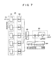
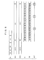
- FIG. 7 and 8 Another embodiment of the present invention will be given referring to Figs. 7 and 8.
- This embodiment is featured in that the interpolation is performed in brightness/color-difference separation circuit.
- input signals IN correpsonding to the n-th pixel are Yn, Gn and Cn
- interpolated luminance and color-difference signals are In, C1n and C2n
- the interpolation processing is achieved as follows:
- This expression can be considered to be a combination of expression (1) for the brightness/color-difference separation, and expression (2) for the interpolation in the first embodiment. This means that the interpolation and the brightness/color-difference separation can both be processed by a single circuit.
- the brightness/color-difference separation circuit of this embodiment comprises a serial/parallel conversion circuit 80, a select circuit 83 for sequentially selecting one of five outputs of converter 80, a select circuit 84 for sequentially selecting one of 15 parameters aij, and a sum-of-products operation circuit 85 for performing a sum-of-products operation using output data of selectors 83 and 84, viz. for applying a matrix operation to color signals from selector 83.
- the parallel/serial conversion circuit 80 includes a serial shift registers 81 having five stages each storing a color signal, and parallel register 82 having five stages connected in parallel to the stages of register 81.
- In registers 81 and 82 are stored color signals Yn, Gn and Cn for the n-th pixel, and color signals Gn-1 and Cn-1 for the (n-1 )th pixel preceding to the n-th pixel.
- the sum-of-products operation is performed fifteen times within the transfer time of one pixel, using the five outputs of parallel register 82 and the fifteen parameters all to a35, so that the interpolated output signals In, C1 n and C2n are produced by the above matrix operation.
- the parameters all to a35 may be varied to enhance the flexibility of the interpolation processing.
- FIG. 9 A further embodiment of the present invention will be described referring to Fig. 9.
- the following matrix expression describes the interpolating process of this embodiment.
- the embodiment performs both the brightness/color-difference separation and the interpolation, using the color signals Gn-1, Cn-1, Yn and Gn. It is assumed that the positions of the color light receiving elements for producing color signals Yn, Gn and Cn are P(Yn), P(Gn) and P(Cn), as shown in Fig. 9.
- the G signal at P(Yn) interpolated by Gn and Gn-1 as Gn-1/3 + 2Gn/3 is used for interpolation of the signal C1.
- an interpolated signal G) 2Gn-1/3 + Gn/3) at P(Cn-1) is used.
- C1n is derived from a color signal and an interpolated color signal at the same point. This is the case for C2n.
- C1 n and C2n are signals at different points.
- C1n, C2n represent signals at different points. The errors caused in the color difference signals due to brightness variation can be substantially removed.
- the present embodiment has advantages that, because of the matrix operation of 3 x 4, the number of stages of the serial and parallel registers is reduced, and the times of the sum-of-products operations is reduced to 12.
- a fourth embodiment of the present invention will be described referring to Fig. 10.
- a pair of light receiving elements are provided for each of colours Y, G and C of one pixel. Output signals of each pair of the light receiving elements are added together. Three added signals are output as three color output signals of one pixel.
- the color signal Gn-1 is the sum of output signals of light receiving elements at coordinates 1 and 4, and therefore indicates color information G at coordinate 2.5.
- the color signals Cn-1, Yn, Gn and Cn likewise represent color information at the coordinates 3.5, 7.5, 8.5, and 9.5, respectively.
- the color signals at coordinate 7.5 for example, can be obtained by
- the light receiving array of this embodiment brings about an advantage as given below.
- the attenuation of its spatial frequency characteristic is small in a region beyond the Nyquist frequency 1 VI so that the areasing noise is large.
- the attenuation is large, and therefore the areasing noise is reduced. I indicates the length of one pixel.
- each pixel contains four elements on which color filters of red (R), green (G), blue (B) and green (G) are arranged in this order.
Landscapes
- Engineering & Computer Science (AREA)
- Multimedia (AREA)
- Signal Processing (AREA)
- Color Image Communication Systems (AREA)
- Facsimile Image Signal Circuits (AREA)
- Facsimile Scanning Arrangements (AREA)
Claims (11)
un circuit d'opération d'interpolation (40, 23) connecté de façon à recevoir les signaux de couleurs provenant du réseau (13) d'éléments récepteurs de lumière de couleur pour exécuter une opération d'interpolation entre les signaux de couleurs pour les éléments d'image ou pixels adjacents afin de réduire les erreurs dans les signaux de couleurs représentant un élément d'image, erreurs qui sont provoquées par des différences de position entre lesdits éléments récepteurs de lumière définissant chaque élément d'image.
dans lequel ledit circuit d'opération d'interpolation (40) est disposé à l'étape précédent ledit circuit (23) de formation du signal de brillance/différence de couleurs.


Applications Claiming Priority (2)
| Application Number | Priority Date | Filing Date | Title |
|---|---|---|---|
| JP274128/84 | 1984-12-27 | ||
| JP59274128A JP2537172B2 (ja) | 1984-12-27 | 1984-12-27 | カラ−画像入力装置 |
Publications (3)
| Publication Number | Publication Date |
|---|---|
| EP0187534A2 EP0187534A2 (fr) | 1986-07-16 |
| EP0187534A3 EP0187534A3 (en) | 1987-06-03 |
| EP0187534B1 true EP0187534B1 (fr) | 1990-09-19 |
Family
ID=17537405
Family Applications (1)
| Application Number | Title | Priority Date | Filing Date |
|---|---|---|---|
| EP85309505A Expired EP0187534B1 (fr) | 1984-12-27 | 1985-12-24 | Appareil de traitement du signal couleur avec une fonction d'interpolation de signal pour utilisation dans un duplicateur en couleurs |
Country Status (4)
| Country | Link |
|---|---|
| US (1) | US4672433A (fr) |
| EP (1) | EP0187534B1 (fr) |
| JP (1) | JP2537172B2 (fr) |
| DE (1) | DE3579801D1 (fr) |
Families Citing this family (33)
| Publication number | Priority date | Publication date | Assignee | Title |
|---|---|---|---|---|
| JPS61214862A (ja) * | 1985-03-21 | 1986-09-24 | Canon Inc | カラ−画像形成方法 |
| US4758885A (en) * | 1985-06-17 | 1988-07-19 | Canon Kabushiki Kaisha | Method of processing color image |
| US4837614A (en) * | 1986-08-20 | 1989-06-06 | Ricoh Company, Ltd. | Color image processing method |
| JPH0810901B2 (ja) * | 1986-09-05 | 1996-01-31 | 富士ゼロックス株式会社 | 色識別装置 |
| JPS63141441A (ja) * | 1986-12-03 | 1988-06-13 | Konica Corp | カラ−画像処理装置 |
| US4876610A (en) * | 1986-12-25 | 1989-10-24 | Canon Kabushiki Kaisha | Image processing apparatus with binarization-error dispersal |
| JP2585271B2 (ja) * | 1987-06-02 | 1997-02-26 | 株式会社東芝 | カラー画像処理方法 |
| JPH0198367A (ja) * | 1987-10-12 | 1989-04-17 | Fuji Xerox Co Ltd | 二色画像読取り装置 |
| US4958218A (en) * | 1987-12-16 | 1990-09-18 | Canon Kabushiki Kaisha | Image processing method and apparatus with dot-processing |
| JP2683014B2 (ja) * | 1988-03-08 | 1997-11-26 | キヤノン株式会社 | 画像処理方法及び装置 |
| DE3943762C2 (de) * | 1988-03-29 | 1997-03-06 | Mitsubishi Electric Corp | Farbbildabtasteinrichtung |
| US4992860A (en) * | 1988-03-29 | 1991-02-12 | Mitsubishi Denki Kabushiki Kaisha | Color scanning system |
| US5031034A (en) * | 1988-06-20 | 1991-07-09 | Canon Kabushiki Kaisha | Image forming and processing apparatus with identification of character portions of images |
| GB8824340D0 (en) * | 1988-10-18 | 1988-11-23 | Xerox Corp | Colour detection/recognition apparatus |
| DE3836765A1 (de) * | 1988-10-28 | 1990-05-03 | Thomson Brandt Gmbh | Telefaxsystem |
| CA2012405A1 (fr) * | 1989-06-19 | 1990-12-19 | John J. Deacon | Methode et dispositif de changement rapide des dimensions d'une image en couleurs affichee |
| US5175701A (en) * | 1989-07-25 | 1992-12-29 | Eastman Kodak Company | System for performing linear interpolation |
| US5136401A (en) * | 1989-12-08 | 1992-08-04 | Kabushiki Kaisha Toshiba | Image layout apparatus for performing pattern modification such as coloring of an original image |
| US5138699A (en) * | 1990-02-13 | 1992-08-11 | International Business Machines Corporation | Hardware utilization of color interpolation capability in a color imaging system |
| JPH04150170A (ja) * | 1990-10-09 | 1992-05-22 | Matsushita Electric Ind Co Ltd | カラー画像読取方法およびその装置 |
| US5479534A (en) * | 1990-11-29 | 1995-12-26 | Konica Corporation | Image reading apparatus |
| JP3253125B2 (ja) * | 1991-07-04 | 2002-02-04 | 株式会社東芝 | カラー画像読取り補正装置 |
| JP3217398B2 (ja) * | 1991-08-09 | 2001-10-09 | キヤノン株式会社 | 画像読取装置 |
| US5185661A (en) * | 1991-09-19 | 1993-02-09 | Eastman Kodak Company | Input scanner color mapping and input/output color gamut transformation |
| DE4136646A1 (de) * | 1991-11-07 | 1993-05-13 | Hell Ag Linotype | Verfahren zur abastung von farbvorlagen sowie einrichtung zur durchfuehrung des verfahrens |
| JP2738902B2 (ja) * | 1993-06-25 | 1998-04-08 | キヤノン株式会社 | カラー画像処理装置 |
| JPH07222011A (ja) | 1994-01-31 | 1995-08-18 | Canon Inc | 色再現範囲表現方法及び画像処理方法及び装置 |
| DE19836138A1 (de) * | 1998-08-10 | 2000-02-17 | Heidelberger Druckmasch Ag | Verfahren zur Berechnung von Farbwerten |
| US6674926B1 (en) * | 1999-04-09 | 2004-01-06 | Eastman Kodak Company | Controller for a multiple array color sensor |
| JP5440110B2 (ja) | 2009-03-30 | 2014-03-12 | 株式会社リコー | 分光特性取得装置、分光特性取得方法、画像評価装置、及び画像形成装置 |
| JP2012173163A (ja) * | 2011-02-22 | 2012-09-10 | Ricoh Co Ltd | 分光計測装置、画像形成装置、分光計測方法、プログラム及び記録媒体 |
| JP6039948B2 (ja) * | 2012-07-17 | 2016-12-07 | ローム株式会社 | 画像読取装置 |
| CN111093459A (zh) * | 2017-10-04 | 2020-05-01 | 奥林巴斯株式会社 | 内窥镜装置、图像处理方法以及程序 |
Family Cites Families (9)
| Publication number | Priority date | Publication date | Assignee | Title |
|---|---|---|---|---|
| JPS57208765A (en) * | 1981-06-18 | 1982-12-21 | Dainippon Screen Mfg Co Ltd | Signal interpolating method for memory device |
| JPS58128078A (ja) * | 1982-01-27 | 1983-07-30 | Dainippon Screen Mfg Co Ltd | メモリ装置の構成方法 |
| JPS58211154A (ja) * | 1982-06-01 | 1983-12-08 | Dainippon Screen Mfg Co Ltd | レタツチ機能を有する画像走査記録方法及び装置 |
| EP0110353B2 (fr) * | 1982-11-30 | 1990-03-21 | Kabushiki Kaisha Toshiba | Système de traitement de signal d'image approprié à affichage d'images en demi-teinte |
| JPS59128872A (ja) * | 1983-01-14 | 1984-07-25 | Fuji Xerox Co Ltd | カラ−画情報処理装置 |
| JPS59211377A (ja) * | 1983-05-17 | 1984-11-30 | Toshiba Corp | カラ−リニアイメ−ジセンサの信号処理方法 |
| JPS6038973A (ja) * | 1983-08-11 | 1985-02-28 | Dainippon Screen Mfg Co Ltd | 境界画素の処理方法 |
| JPS60105376A (ja) * | 1983-11-14 | 1985-06-10 | Toshiba Corp | カラ−画像出力装置 |
| EP0144461B1 (fr) * | 1983-12-14 | 1987-05-20 | DR.-ING. RUDOLF HELL GmbH | Procédé et circuit pour la reconnaissance de chrominances et des couleurs |
-
1984
- 1984-12-27 JP JP59274128A patent/JP2537172B2/ja not_active Expired - Lifetime
-
1985
- 1985-12-20 US US06/811,477 patent/US4672433A/en not_active Expired - Lifetime
- 1985-12-24 EP EP85309505A patent/EP0187534B1/fr not_active Expired
- 1985-12-24 DE DE8585309505T patent/DE3579801D1/de not_active Expired - Lifetime
Also Published As
| Publication number | Publication date |
|---|---|
| DE3579801D1 (de) | 1990-10-25 |
| US4672433A (en) | 1987-06-09 |
| JPS61154357A (ja) | 1986-07-14 |
| JP2537172B2 (ja) | 1996-09-25 |
| EP0187534A3 (en) | 1987-06-03 |
| EP0187534A2 (fr) | 1986-07-16 |
Similar Documents
| Publication | Publication Date | Title |
|---|---|---|
| EP0187534B1 (fr) | Appareil de traitement du signal couleur avec une fonction d'interpolation de signal pour utilisation dans un duplicateur en couleurs | |
| US4844288A (en) | Reproduction picture sharpness emphasizing method and apparatus | |
| EP0168818B1 (fr) | Appareil à copier pour images en couleurs | |
| EP0110353B1 (fr) | Système de traitement de signal d'image approprié à affichage d'images en demi-teinte | |
| US4974072A (en) | Image reading apparatus having a plurality of line sensors and means for correcting crosstalk therebetween | |
| US5734801A (en) | Method of and apparatus for producing color proof | |
| US5781709A (en) | Method of and apparatus for generating proof | |
| US5130820A (en) | Image processing device | |
| US5253083A (en) | Image reading apparatus having improved shading correction | |
| US4839719A (en) | Color image reading apparatus with an improved sensor | |
| EP0542513B1 (fr) | Appareil de lecture d'images en couleurs | |
| EP0523898B1 (fr) | Procédé d'expression de couleurs, appareil de lecture d'images en couleurs et appareil de traitement d'images en couleurs | |
| US5313313A (en) | Image processing apparatus | |
| EP0211509A2 (fr) | Procédé pour l'impression d'images en couleur | |
| US5196927A (en) | Method for electronic color processing | |
| US5506698A (en) | Image reproducing apparatus and process wherein minimized average error technique is used for each of fractions of original pel intensity value | |
| US5361139A (en) | Method for producing a multitone image | |
| JP3133409B2 (ja) | ディジタルカラー複写装置 | |
| JPH02272878A (ja) | 原稿読取装置 | |
| JP2941852B2 (ja) | 画像処理方法 | |
| JPH0242875A (ja) | カラー画像読取り装置 | |
| JPH04150170A (ja) | カラー画像読取方法およびその装置 | |
| JPS63246966A (ja) | カラ−画像入力装置 | |
| JPS63187965A (ja) | カラ−画像読取方式 | |
| JPH0514695A (ja) | 色補正係数決定装置 |
Legal Events
| Date | Code | Title | Description |
|---|---|---|---|
| PUAI | Public reference made under article 153(3) epc to a published international application that has entered the european phase |
Free format text: ORIGINAL CODE: 0009012 |
|
| AK | Designated contracting states |
Kind code of ref document: A2 Designated state(s): DE FR GB IT NL |
|
| 17P | Request for examination filed |
Effective date: 19861002 |
|
| PUAL | Search report despatched |
Free format text: ORIGINAL CODE: 0009013 |
|
| AK | Designated contracting states |
Kind code of ref document: A3 Designated state(s): DE FR GB IT NL |
|
| 17Q | First examination report despatched |
Effective date: 19891211 |
|
| GRAA | (expected) grant |
Free format text: ORIGINAL CODE: 0009210 |
|
| AK | Designated contracting states |
Kind code of ref document: B1 Designated state(s): DE FR GB IT NL |
|
| REF | Corresponds to: |
Ref document number: 3579801 Country of ref document: DE Date of ref document: 19901025 |
|
| ITF | It: translation for a ep patent filed | ||
| ET | Fr: translation filed | ||
| ITTA | It: last paid annual fee | ||
| PLBE | No opposition filed within time limit |
Free format text: ORIGINAL CODE: 0009261 |
|
| STAA | Information on the status of an ep patent application or granted ep patent |
Free format text: STATUS: NO OPPOSITION FILED WITHIN TIME LIMIT |
|
| 26N | No opposition filed | ||
| PGFP | Annual fee paid to national office [announced via postgrant information from national office to epo] |
Ref country code: FR Payment date: 19971209 Year of fee payment: 13 |
|
| PGFP | Annual fee paid to national office [announced via postgrant information from national office to epo] |
Ref country code: GB Payment date: 19971215 Year of fee payment: 13 |
|
| PGFP | Annual fee paid to national office [announced via postgrant information from national office to epo] |
Ref country code: NL Payment date: 19971223 Year of fee payment: 13 |
|
| PGFP | Annual fee paid to national office [announced via postgrant information from national office to epo] |
Ref country code: DE Payment date: 19980105 Year of fee payment: 13 |
|
| PG25 | Lapsed in a contracting state [announced via postgrant information from national office to epo] |
Ref country code: GB Free format text: LAPSE BECAUSE OF NON-PAYMENT OF DUE FEES Effective date: 19981224 |
|
| PG25 | Lapsed in a contracting state [announced via postgrant information from national office to epo] |
Ref country code: NL Free format text: LAPSE BECAUSE OF NON-PAYMENT OF DUE FEES Effective date: 19990701 |
|
| GBPC | Gb: european patent ceased through non-payment of renewal fee |
Effective date: 19981224 |
|
| PG25 | Lapsed in a contracting state [announced via postgrant information from national office to epo] |
Ref country code: FR Free format text: LAPSE BECAUSE OF NON-PAYMENT OF DUE FEES Effective date: 19990831 |
|
| NLV4 | Nl: lapsed or anulled due to non-payment of the annual fee |
Effective date: 19990701 |
|
| REG | Reference to a national code |
Ref country code: FR Ref legal event code: ST |
|
| PG25 | Lapsed in a contracting state [announced via postgrant information from national office to epo] |
Ref country code: DE Free format text: LAPSE BECAUSE OF NON-PAYMENT OF DUE FEES Effective date: 19991001 |