EP0187582A1 - Pressscheibe zum Strangpressen von Metall - Google Patents
Pressscheibe zum Strangpressen von Metall Download PDFInfo
- Publication number
- EP0187582A1 EP0187582A1 EP85402437A EP85402437A EP0187582A1 EP 0187582 A1 EP0187582 A1 EP 0187582A1 EP 85402437 A EP85402437 A EP 85402437A EP 85402437 A EP85402437 A EP 85402437A EP 0187582 A1 EP0187582 A1 EP 0187582A1
- Authority
- EP
- European Patent Office
- Prior art keywords
- face
- recess
- billet
- frustoconical
- grain
- Prior art date
- Legal status (The legal status is an assumption and is not a legal conclusion. Google has not performed a legal analysis and makes no representation as to the accuracy of the status listed.)
- Granted
Links
Images
Classifications
-
- B—PERFORMING OPERATIONS; TRANSPORTING
- B21—MECHANICAL METAL-WORKING WITHOUT ESSENTIALLY REMOVING MATERIAL; PUNCHING METAL
- B21C—MANUFACTURE OF METAL SHEETS, WIRE, RODS, TUBES, PROFILES OR LIKE SEMI-MANUFACTURED PRODUCTS OTHERWISE THAN BY ROLLING; AUXILIARY OPERATIONS USED IN CONNECTION WITH METAL-WORKING WITHOUT ESSENTIALLY REMOVING MATERIAL
- B21C26/00—Rams or plungers for metal extruding; Discs therefor
Definitions
- the subject of the invention is a thrust grain which can be used for a spinning press for non-ferrous metallic materials, in particular aluminum.
- a press for spinning non-ferrous metals generally comprises a container provided with a cylindrical housing in which is placed a billet, that is to say a section of bar constituting the metal to be spun.
- a billet that is to say a section of bar constituting the metal to be spun.
- One of the ends of the housing is closed by a bottom carrying a die centered on the axis of the housing and against which the billet is pushed with strong pressure to form by extrusion a profile whose cross section corresponds to that of the die.
- the spinning pressure is exerted by a pushing ram consisting of a rod centered on the spinning axis and moving parallel to the axis under the action of pushing means, penetrating into the housing to extrude the metal by the sector.
- the gland is mounted on the fixed tool holder and carries the die at its end.
- the container is then pushed by the movable cross member towards the gland on which it is threaded by forcing the metal of the billet to pass through the die placed at the end of the gland, the latter being provided with an axial bore for the passage of the extruded profile.
- the extruded profile remains fixed on a metal base which remains between the thrust face of the grain and the bottom of the container carrying the die.
- the profile is sheared so as to separate it from the base but the grain remains wedged between the base and the aluminum film which remains inside the housing and it is no longer possible to return it back through the container without scrape the internal wall of the housing, removing the film and risking scratching the housing.
- it is generally preferred to separate the grain from the gland and remove it with the base on the side opposite to that of the gland. The grain must then be cleaned and then replaced at the end of the gland for a new spinning operation.
- the subject of the invention is a new arrangement which allows on the one hand to limit the crushing of the grain and on the other hand to better control its increase in diameter and therefore the thickness of the protective film.
- the grain fixing part is made of a metal hard enough to resist crushing and the cylindrical sleeve is made of a less hard and more elastic metal to facilitate its expansion.
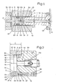
- FIG 1 there is shown only the gland 1 of a spinning press, fixed on a movable cross member 11, actuated by a thrust cylinder not shown.
- the gland 1 enters the interior of a housing 2 formed in a container 21 which bears on the bed base 22 by means of the die 23 centered on the axis 10 of the housing 2 and closing the latter.
- the general arrangement of a spinning press has been known for a long time and does not require a detailed description.
- the arrangements according to the invention are specially provided for the use of a harnessed grain.
- the grain 3 is fixed to the end of a rod 14 which passes through the gland 1 in the axis thereof and whose, for example, the threaded end 15 can engage on a bore 31 internally threaded and formed on the rear face 32 of the grain facing the gland.
- the hollow disc 3 consists of two separate parts, respectively a cylindrical sleeve 6 and a rear fixing part 3.
- the sleeve 6 is formed of a tubular wall whose thickness "1" and the length "L” are determined according to the nature of the metal so that the lip formed by the sleeve 6 around the corner 5 can undergo the necessary diameter variations without excessive fatigue.
- the lip 6 is limited towards the outside by a substantially cylindrical side wall 61 which forms the external face of the grain and which, according to a known arrangement, can flare very slightly forward, on the side of the billet, so to rely on the protective film by a front portion 62 of reduced length.
- the internal face of the sleeve 6 is constituted, towards the front by the frustoconical face 63 on which the frustoconical spacing face 54 of the corner 5 rests and towards the rear, by a cylindrical face 64 centered on the axis 10 and of diameter equal to that of the small base 66 of the frustoconical face 63.
- the fixing part 30 constituting the body of the grain for the most part, has an outside diameter equal to that of the lateral face 61 of the sleeve 6. However, it is provided towards the front with a projecting surface 7 limited by a transverse face 71 perpendicular to the axis and, laterally, by a cylindrical face centered on the axis 10 and of diameter equal to that of the cylindrical internal face 64 of the sleeve 6. The latter can therefore fit together without play on the projecting part 7, the length (A) of which is sufficient to allow the socket to be held.
- the cylindrical lateral face 55 of the wedge is spaced from the cylindrical face 54 of the bush 6 by a clearance that is simply sufficient to allow the displacement of the wedge without other friction than that of the frustoconical faces 54 and 63 one on the other.
- the bottom 71 of the recess therefore has the maximum possible diameter compatible with the thickness "1" that must be given to the socket 6 and the bearing face 56 of the corner also has the maximum possible diameter, slightly less than the diameter from the bottom 71 of the recess 35, the difference corresponding simply to the clearance (a) which must exist between the cylindrical faces 55 and 64. Therefore, for the same external dimension of the grain, the bearing surface of the corner on the bottom of the recess can be increased by around 130X compared to the previous arrangement, which allows a reduction in the stress rate of 30X for an identical thrust force.
Landscapes
- Engineering & Computer Science (AREA)
- Mechanical Engineering (AREA)
- Forging (AREA)
- Extrusion Of Metal (AREA)
- Manufacture Of Alloys Or Alloy Compounds (AREA)
Priority Applications (1)
| Application Number | Priority Date | Filing Date | Title |
|---|---|---|---|
| AT85402437T ATE43519T1 (de) | 1984-12-10 | 1985-12-06 | Pressscheibe zum strangpressen von metall. |
Applications Claiming Priority (2)
| Application Number | Priority Date | Filing Date | Title |
|---|---|---|---|
| FR8418810A FR2574321B1 (fr) | 1984-12-10 | 1984-12-10 | Grain de poussee pour le filage de metal |
| FR8418810 | 1984-12-10 |
Publications (2)
| Publication Number | Publication Date |
|---|---|
| EP0187582A1 true EP0187582A1 (de) | 1986-07-16 |
| EP0187582B1 EP0187582B1 (de) | 1989-05-31 |
Family
ID=9310406
Family Applications (1)
| Application Number | Title | Priority Date | Filing Date |
|---|---|---|---|
| EP85402437A Expired EP0187582B1 (de) | 1984-12-10 | 1985-12-06 | Pressscheibe zum Strangpressen von Metall |
Country Status (4)
| Country | Link |
|---|---|
| EP (1) | EP0187582B1 (de) |
| AT (1) | ATE43519T1 (de) |
| DE (1) | DE3570611D1 (de) |
| FR (1) | FR2574321B1 (de) |
Cited By (1)
| Publication number | Priority date | Publication date | Assignee | Title |
|---|---|---|---|---|
| WO1998003277A1 (en) * | 1996-07-18 | 1998-01-29 | Exco Technologies Limited | Improved dummy block construction |
Citations (3)
| Publication number | Priority date | Publication date | Assignee | Title |
|---|---|---|---|---|
| US2925176A (en) * | 1956-09-14 | 1960-02-16 | Kaiser Aluminium Chem Corp | Dummy head or block for end of extrusion ram |
| US3731519A (en) * | 1971-07-29 | 1973-05-08 | Aluminum Co Of America | Two piece flexing die holder |
| GB2067944A (en) * | 1980-01-26 | 1981-08-05 | Centry Aluminium Co Ltd | Extrusion process |
-
1984
- 1984-12-10 FR FR8418810A patent/FR2574321B1/fr not_active Expired
-
1985
- 1985-12-06 AT AT85402437T patent/ATE43519T1/de not_active IP Right Cessation
- 1985-12-06 DE DE8585402437T patent/DE3570611D1/de not_active Expired
- 1985-12-06 EP EP85402437A patent/EP0187582B1/de not_active Expired
Patent Citations (3)
| Publication number | Priority date | Publication date | Assignee | Title |
|---|---|---|---|---|
| US2925176A (en) * | 1956-09-14 | 1960-02-16 | Kaiser Aluminium Chem Corp | Dummy head or block for end of extrusion ram |
| US3731519A (en) * | 1971-07-29 | 1973-05-08 | Aluminum Co Of America | Two piece flexing die holder |
| GB2067944A (en) * | 1980-01-26 | 1981-08-05 | Centry Aluminium Co Ltd | Extrusion process |
Cited By (2)
| Publication number | Priority date | Publication date | Assignee | Title |
|---|---|---|---|---|
| WO1998003277A1 (en) * | 1996-07-18 | 1998-01-29 | Exco Technologies Limited | Improved dummy block construction |
| US5918498A (en) * | 1996-07-18 | 1999-07-06 | Robbins; Paul H. | Dummy block construction |
Also Published As
| Publication number | Publication date |
|---|---|
| FR2574321B1 (fr) | 1987-02-27 |
| EP0187582B1 (de) | 1989-05-31 |
| ATE43519T1 (de) | 1989-06-15 |
| FR2574321A1 (fr) | 1986-06-13 |
| DE3570611D1 (en) | 1989-07-06 |
Similar Documents
| Publication | Publication Date | Title |
|---|---|---|
| EP0034549B1 (de) | Verfahren zum Einrollen von Rohren in Platten und Werkzeug zur Durchführung dieses Verfahrens | |
| EP2259901B1 (de) | Wiederverwendbare vorübergehende befestigungsvorrichtung zur vormontage von mindestens zwei vorab durchlochten bauteilen | |
| EP3539685B1 (de) | Werkzeug und verfahren zum setzen einer blindbefestigung | |
| EP0381556B1 (de) | Hohlbolzen mit inneren Ausbuchtungen und deren Herstellung | |
| EP0016669B1 (de) | Montagemuffe zum Befestigen einer Schraube in einem Gegenstand, insbesondere aus weichem Material | |
| CH465848A (fr) | Presse à mouler, pour le moulage de pièces en matière thermodurcissable comportant des filetages extérieur et intérieur coaxiaux | |
| EP0286197A2 (de) | Queue für das Billardspiel | |
| FR2473919A1 (fr) | Noyau pour tube a cintrer | |
| EP0117213A1 (de) | Vorrichtung zur Kaltverformung metallischer Werkstücke mit entgegengesetzten Axialteilen | |
| FR2489902A1 (fr) | Element de liaison | |
| EP0714484B1 (de) | Elastisches lager mit mindestens zwei zylindrischen buchsen, buchsen für ein solches lager und fabrikationsprozess des lagers mittels derartigen buchsen | |
| EP0187582B1 (de) | Pressscheibe zum Strangpressen von Metall | |
| EP0533561A1 (de) | Abnehmbare Vorrichtung zum Zusammenfügen von Unterteilen die mit einem Loch vorsehen sind | |
| FR2627405A1 (fr) | Procede de filage de metal, specialement d'aluminium, et presse de filage pour la mise en oeuvre du procede | |
| WO2009101277A2 (fr) | Procédé de sertissage d'un insert dans un support à deux panneaux superposés | |
| FR2842276A1 (fr) | Collier de serrage | |
| EP0491627A2 (de) | Rückstellwerkzeug eines selbsteinstellenden Bremshebels | |
| EP0062567B1 (de) | Fahrzeugscheibenbremse | |
| EP0106751A1 (de) | Verfahren zur Herstellung zylindrischer Werkstücke mit fortschreitend wachsenden Durchmessern und Vorrichtung zur Durchführung des Verfahrens | |
| EP0323931B1 (de) | Verfahren und Werkzeugausrüstung zur Herstellung geschmiedeter Niete | |
| EP0506932A1 (de) | Verfahren und vorrichtung zum einsetzen von einem o-ring in eine nut | |
| FR2494613A1 (fr) | Procede et dispositif d'assemblage non demontable de pieces tournantes, telles que des elements d'arbre | |
| EP0558399B1 (de) | Verfahren zum Verbinden einer Hülse mit einem Rohr und Rohr derart versehen mit einer Hülse | |
| EP1873406A1 (de) | Bördelmutter | |
| FR2537672A1 (fr) | Appareil de fixation aveugle et assemblage comportant un tel appareil |
Legal Events
| Date | Code | Title | Description |
|---|---|---|---|
| PUAI | Public reference made under article 153(3) epc to a published international application that has entered the european phase |
Free format text: ORIGINAL CODE: 0009012 |
|
| AK | Designated contracting states |
Kind code of ref document: A1 Designated state(s): AT BE DE GB IT |
|
| 17P | Request for examination filed |
Effective date: 19860618 |
|
| 17Q | First examination report despatched |
Effective date: 19871030 |
|
| RAP1 | Party data changed (applicant data changed or rights of an application transferred) |
Owner name: CLECIM SA |
|
| GRAA | (expected) grant |
Free format text: ORIGINAL CODE: 0009210 |
|
| AK | Designated contracting states |
Kind code of ref document: B1 Designated state(s): AT BE DE GB IT |
|
| REF | Corresponds to: |
Ref document number: 43519 Country of ref document: AT Date of ref document: 19890615 Kind code of ref document: T |
|
| REF | Corresponds to: |
Ref document number: 3570611 Country of ref document: DE Date of ref document: 19890706 |
|
| GBT | Gb: translation of ep patent filed (gb section 77(6)(a)/1977) | ||
| ITF | It: translation for a ep patent filed | ||
| PGFP | Annual fee paid to national office [announced via postgrant information from national office to epo] |
Ref country code: GB Payment date: 19891231 Year of fee payment: 5 |
|
| PLBI | Opposition filed |
Free format text: ORIGINAL CODE: 0009260 |
|
| 26 | Opposition filed |
Opponent name: SMS HASENCLEVER MASCHINENFABRIK GMBH Effective date: 19900228 |
|
| PG25 | Lapsed in a contracting state [announced via postgrant information from national office to epo] |
Ref country code: GB Effective date: 19901206 |
|
| GBPC | Gb: european patent ceased through non-payment of renewal fee | ||
| ITTA | It: last paid annual fee | ||
| PLBN | Opposition rejected |
Free format text: ORIGINAL CODE: 0009273 |
|
| STAA | Information on the status of an ep patent application or granted ep patent |
Free format text: STATUS: OPPOSITION REJECTED |
|
| 27O | Opposition rejected |
Effective date: 19910712 |
|
| PGFP | Annual fee paid to national office [announced via postgrant information from national office to epo] |
Ref country code: AT Payment date: 19931203 Year of fee payment: 9 |
|
| PG25 | Lapsed in a contracting state [announced via postgrant information from national office to epo] |
Ref country code: AT Effective date: 19941206 |
|
| PGFP | Annual fee paid to national office [announced via postgrant information from national office to epo] |
Ref country code: BE Payment date: 19941212 Year of fee payment: 10 |
|
| PGFP | Annual fee paid to national office [announced via postgrant information from national office to epo] |
Ref country code: DE Payment date: 19950124 Year of fee payment: 10 |
|
| PG25 | Lapsed in a contracting state [announced via postgrant information from national office to epo] |
Ref country code: BE Effective date: 19951231 |
|
| BERE | Be: lapsed |
Owner name: S.A. CLECIM Effective date: 19951231 |
|
| PG25 | Lapsed in a contracting state [announced via postgrant information from national office to epo] |
Ref country code: DE Effective date: 19960903 |
|
| APAH | Appeal reference modified |
Free format text: ORIGINAL CODE: EPIDOSCREFNO |