EP0187601A2 - Trockenes Ätzverfahren für eine Siliziumnitridschicht - Google Patents
Trockenes Ätzverfahren für eine Siliziumnitridschicht Download PDFInfo
- Publication number
- EP0187601A2 EP0187601A2 EP85402634A EP85402634A EP0187601A2 EP 0187601 A2 EP0187601 A2 EP 0187601A2 EP 85402634 A EP85402634 A EP 85402634A EP 85402634 A EP85402634 A EP 85402634A EP 0187601 A2 EP0187601 A2 EP 0187601A2
- Authority
- EP
- European Patent Office
- Prior art keywords
- layer
- silicon
- silicon nitride
- nitride layer
- etching
- Prior art date
- Legal status (The legal status is an assumption and is not a legal conclusion. Google has not performed a legal analysis and makes no representation as to the accuracy of the status listed.)
- Granted
Links
Images


Classifications
-
- H—ELECTRICITY
- H10—SEMICONDUCTOR DEVICES; ELECTRIC SOLID-STATE DEVICES NOT OTHERWISE PROVIDED FOR
- H10P—GENERIC PROCESSES OR APPARATUS FOR THE MANUFACTURE OR TREATMENT OF DEVICES COVERED BY CLASS H10
- H10P14/00—Formation of materials, e.g. in the shape of layers or pillars
- H10P14/60—Formation of materials, e.g. in the shape of layers or pillars of insulating materials
- H10P14/61—Formation of materials, e.g. in the shape of layers or pillars of insulating materials using masks
-
- H—ELECTRICITY
- H10—SEMICONDUCTOR DEVICES; ELECTRIC SOLID-STATE DEVICES NOT OTHERWISE PROVIDED FOR
- H10P—GENERIC PROCESSES OR APPARATUS FOR THE MANUFACTURE OR TREATMENT OF DEVICES COVERED BY CLASS H10
- H10P50/00—Etching of wafers, substrates or parts of devices
- H10P50/20—Dry etching; Plasma etching; Reactive-ion etching
- H10P50/28—Dry etching; Plasma etching; Reactive-ion etching of insulating materials
- H10P50/282—Dry etching; Plasma etching; Reactive-ion etching of insulating materials of inorganic materials
- H10P50/283—Dry etching; Plasma etching; Reactive-ion etching of insulating materials of inorganic materials by chemical means
-
- H—ELECTRICITY
- H10—SEMICONDUCTOR DEVICES; ELECTRIC SOLID-STATE DEVICES NOT OTHERWISE PROVIDED FOR
- H10W—GENERIC PACKAGES, INTERCONNECTIONS, CONNECTORS OR OTHER CONSTRUCTIONAL DETAILS OF DEVICES COVERED BY CLASS H10
- H10W10/00—Isolation regions in semiconductor bodies between components of integrated devices
- H10W10/01—Manufacture or treatment
- H10W10/011—Manufacture or treatment of isolation regions comprising dielectric materials
- H10W10/012—Manufacture or treatment of isolation regions comprising dielectric materials using local oxidation of silicon [LOCOS]
-
- H—ELECTRICITY
- H10—SEMICONDUCTOR DEVICES; ELECTRIC SOLID-STATE DEVICES NOT OTHERWISE PROVIDED FOR
- H10W—GENERIC PACKAGES, INTERCONNECTIONS, CONNECTORS OR OTHER CONSTRUCTIONAL DETAILS OF DEVICES COVERED BY CLASS H10
- H10W10/00—Isolation regions in semiconductor bodies between components of integrated devices
- H10W10/10—Isolation regions comprising dielectric materials
- H10W10/13—Isolation regions comprising dielectric materials formed using local oxidation of silicon [LOCOS], e.g. sealed interface localised oxidation [SILO] or side-wall mask isolation [SWAMI]
Definitions
- the present invention relates to a process for etching a silicon nitride layer. Move specifically, it relates to a process for dry etching a silicon nitride layer on a silicon dioxide layer, useful in a so-called "local oxidation of silicon” (LOCOS) process.
- LOC local oxidation of silicon
- a silicon nitride (Si 3 N 4 ) layer is used as a mask for locally oxidizing a semiconductor bulk, such as a silicon bulk.
- a silicon bulk such as a silicon bulk.
- LOC silicon nitride
- the overall surface of a silicon bulk is first oxidized to a thin thickness, e.g., 50 nm.
- an Si 3 N 4 layer of, e.g., 100 nm thickness is formed on the oxidized surface of the silicon bulk.
- the Si 3 N 4 layer is patterned with a mask of a patterned resist layer formed on the si 3 N 4 layer, the resist layer is removed, then the silicon bulk is locally oxidized by using the patterned Si 3 N 4 layer as a mask.
- An etching gas comprising fluoromethane (fleon), particularly tetrafluoromethane (CF 4 ), and oxigen (O 2 ) is typically used for dry etching an Si 3 N 4 layer in the LOCOS process, which gas needs the above mentioned combination of thicknesses of the SiO 2 and Si 3 N 4 layers of, e.g., 50 nm and 100 nm, respectively, since the above etching gas has a ratio of etching rate of Si 3 N 4 to SiO 2 of about 2 to 3 at the highest.
- fluoromethane fluoromethane
- CF 4 tetrafluoromethane
- O 2 oxigen
- the Si0 2 layer may be over etched during the patterning or etching of an Si 3 N 4 layer on the Si0 2 layer, which causes nonuniform oxidation of the silicon bulk existing under the SiO 2 layer.
- etching gases for example, a mixed gas of sulfur hexafluoride (SF 6 ) and chlorine (C1 2 ) for etching silicon (Japanese Unexamined Patent Publication (Kokai) No. 58-7829); a gas of SF 6 , nitrogen trifluoride (NF 3 ), fluorine (F 2 ), or C1 2 for etching silicon (Japanese Unexamined Patent Publication (Kokai) No. 59-214226); a gas of NF 3 for etching Si 3 N 4 (Japanese Unexamined Patent Publication (Kokai) No.
- the main object of the present invention is to provide an effective dry etching process for etching Si 3 N 4 .
- a further object of the present invention is to provide a dry etching process having a high ratio of etching rate of Si 3 N 4 /Si0 2 , useful for the LOCOS process.
- a still further object of the present invention is to reduce the size of "bird beaks" formed in the LOCOS process in order to densify semiconductor IC devices.
- a process for dry etching an Si 3 N 4 layer with an etching gas comprising SF 6 is based on a finding that SF 6 has a high effectivity of etching Si 3 N 4 and a high selectivity of etching Si 3 N 4 in relation to SiO 2 or a photoresist.
- the etching gas optionally further comprises, e.g., fluoromethane such as CH 3 F, CH 2 F 2 , CHF 3 , and CF 4 .
- fluoromethane such as CH 3 F, CH 2 F 2 , CHF 3 , and CF 4 .
- a combination of SF 6 and CH 2 F 2 is preferred.
- anode coupling reactive ion etching is preferable in a process for dry etching an Si 3 N 4 layer on an Si0 2 layer with an etching gas comprising SF 6 and optionally CH 2 F 2 since it allows a higher etching rate ratio of Si 3 N 4 /SiO 2 , although other types of dry etching, for example, cathode coupling type, reactive ion etching, and downflow type plasma etching, may have some advantages in a process according to the present invention.
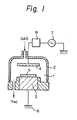
- Figure 1 illustrates an anode coupling type dry etching apparatus.
- a reaction chamber 1 defined by a quartz tube 2
- An upper side electrode 3 is made of aluminum (Al) and anodized on its surface
- a lower side electrode 4 is made of aluminum on which a wafer 5 to be treated is placed.
- the lower side electrode 4 is connected to the ground 6, and the upper side electrode 3 is connected to a radio frequency (RF) source 7 of 13.56 MHz.
- RF radio frequency
- a matching network 8 is inserted between the upper side electrode 3 and the RF source 7.
- the reaction chamber 1 is evacuated by a vacuum pump (not shown).
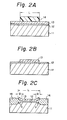
- a silicon (Si) bulk or wafer 11 was prepared and a surface of the silicon bulk 11 was oxidized to form an Si0 2 layer 12 of 30 nm thickness.
- An Si 3 N 4 layer 13 was deposited onto the SiO 2 layer 12 by sputtering, etc. The thickness of the Si 3 N 4 layer 13 was 100 nm in this case, but could have also been made 150 nm.
- a resist layer 14 was coated on the Si 3 N 4 layer 13 and patterned to leave a square or rectangular shape having a size L of 2.5 um.
- a dry etching apparatus as in Fig. 1, the wafer 1 was placed on the lower side electrode 4.
- a radio frequency of 13.56 MHz was applied between the two electrodes 3 and 4 at a power of about 125 Watts.
- a portion of the Si 3 N 4 layer 13 which was not covered with the patterned resist layer 14, was selectively etched or removed.
- the resist layer 14 was then removed.
- a patterned Si 3 N 4 layer 13 was obtained on the SiO 2 layer 12; the patterned Si 3 N 4 layer 13 having a square or rectangular shape, as shown in Fig. 2B.
- oxidation was carried out in which the patterned Si 3 N 4 layer 13 was used as a mask to locally oxidize the silicon bulk 11, that is, a portion of the silicon bulk 11 above which no Si 3 N 4 layer exists was oxidized to form a thick Si0 2 layer 14 or a locally oxidized silicon.
- "bird beaks" b were formed but had the width B of only 0.2 ⁇ m to 0.3 ⁇ m which was reduced from the width of the "bird beaks" in the prior art.
- the thickness of the Si0 2 layer had to be 50 nm if the Si 3 N 4 layer had a thickness of 100 nm. This resulted in a width of the "bird beaks" of 0.3 ⁇ m to 0.4 ⁇ m after patterning the Si 3 N 4 layer and oxidizing the silicon bulk under the SiO 2 layer using the Si 3 N 4 layer as a mask.
- the thickness of an Si 3 N 4 layer was made 150 nm while maintaining the thickness of an SiO 2 layer at 30 nm. Successful selective etching of the Si 3 N 4 layer could be done, that is, the Si0 2 layer was not overetched, resulting in excellent local oxidation of a silicon bulk under the Si0 2 layer.
- the flow rate of CH 2 F 2 was varied with the other conditions being fixed.
- the fixed conditions of the test were vacuum of 0.25 Torr, RF power of 125 Watts, flow rate of the SF 6 of 50 SCCM, and temperature of 25°C.
- the etching rates of an Si 3 N 4 layer, an SiO 2 layer, and a resist layer were determined.
- the obtained etching rates and the selectivities of Si 3 N 4 to SiO 2 and resist or ratios of the etching rate of Si 3 N 4 to Si0 2 and resist, respectively, are summarized in the graphs in Figs. 3 and 4.
- a selectivity of etching of Si 3 N 4 to Si0 2 of more than 3, particularly, more than 4 was obtained in a process according to the present invention while at the highest only a selectivity of 2 to 3 could be obtained in a process in the prior art.
- a relatively high selectivity of etching of Si 3 N 4 /resist was obtained and is also preferable.
- a mixing ratio by volume or mole of CH 2 F 2 :CF 6 of up to 35:100, more preferably 8 - 24:100, particularly 20:100, is preferably used in a process according to the present invention. This fact was ascertained in another test in which the flow-rate of CF 6 is varied with the other conditions being fixed.
- a third test in which the degree of vacuum in a reaction chamber was varied and the other conditions were fixed was carried out.
Landscapes
- Drying Of Semiconductors (AREA)
Applications Claiming Priority (2)
| Application Number | Priority Date | Filing Date | Title |
|---|---|---|---|
| JP59280138A JPS61158143A (ja) | 1984-12-29 | 1984-12-29 | 窒化シリコン膜のエッチング方法 |
| JP280138/84 | 1984-12-29 |
Publications (3)
| Publication Number | Publication Date |
|---|---|
| EP0187601A2 true EP0187601A2 (de) | 1986-07-16 |
| EP0187601A3 EP0187601A3 (en) | 1988-03-16 |
| EP0187601B1 EP0187601B1 (de) | 1991-03-13 |
Family
ID=17620865
Family Applications (1)
| Application Number | Title | Priority Date | Filing Date |
|---|---|---|---|
| EP85402634A Expired - Lifetime EP0187601B1 (de) | 1984-12-29 | 1985-12-26 | Trockenes Ätzverfahren für eine Siliziumnitridschicht |
Country Status (4)
| Country | Link |
|---|---|
| EP (1) | EP0187601B1 (de) |
| JP (1) | JPS61158143A (de) |
| KR (1) | KR900006020B1 (de) |
| DE (1) | DE3582146D1 (de) |
Cited By (1)
| Publication number | Priority date | Publication date | Assignee | Title |
|---|---|---|---|---|
| WO2003012829A1 (de) * | 2001-07-24 | 2003-02-13 | Osram Opto Semiconductors Gmbh | Verfahren zur herstellung einer linse |
Families Citing this family (1)
| Publication number | Priority date | Publication date | Assignee | Title |
|---|---|---|---|---|
| JP2720962B2 (ja) * | 1985-10-29 | 1998-03-04 | ソニー株式会社 | エツチングガス及びこれを用いたエツチング方法 |
Family Cites Families (3)
| Publication number | Priority date | Publication date | Assignee | Title |
|---|---|---|---|---|
| NL8204437A (nl) * | 1982-11-16 | 1984-06-18 | Philips Nv | Werkwijze voor het vervaardigen van een halfgeleiderinrichting met behulp van plasma-etsen. |
| DE3420347A1 (de) * | 1983-06-01 | 1984-12-06 | Hitachi, Ltd., Tokio/Tokyo | Gas und verfahren zum selektiven aetzen von siliciumnitrid |
| JPH0612765B2 (ja) * | 1983-06-01 | 1994-02-16 | 株式会社日立製作所 | エ ッ チ ン グ 方 法 |
-
1984
- 1984-12-29 JP JP59280138A patent/JPS61158143A/ja active Granted
-
1985
- 1985-12-26 DE DE8585402634T patent/DE3582146D1/de not_active Expired - Lifetime
- 1985-12-26 EP EP85402634A patent/EP0187601B1/de not_active Expired - Lifetime
- 1985-12-28 KR KR1019850010029A patent/KR900006020B1/ko not_active Expired
Cited By (1)
| Publication number | Priority date | Publication date | Assignee | Title |
|---|---|---|---|---|
| WO2003012829A1 (de) * | 2001-07-24 | 2003-02-13 | Osram Opto Semiconductors Gmbh | Verfahren zur herstellung einer linse |
Also Published As
| Publication number | Publication date |
|---|---|
| EP0187601B1 (de) | 1991-03-13 |
| DE3582146D1 (de) | 1991-04-18 |
| JPS61158143A (ja) | 1986-07-17 |
| JPH0426539B2 (de) | 1992-05-07 |
| KR860005431A (ko) | 1986-07-23 |
| KR900006020B1 (ko) | 1990-08-20 |
| EP0187601A3 (en) | 1988-03-16 |
Similar Documents
| Publication | Publication Date | Title |
|---|---|---|
| US7541270B2 (en) | Methods for forming openings in doped silicon dioxide | |
| US6015760A (en) | Method for enhancing oxide to nitride selectivity through the use of independent heat control | |
| US8093155B2 (en) | Method of controlling striations and CD loss in contact oxide etch | |
| US5013398A (en) | Anisotropic etch method for a sandwich structure | |
| US7166535B2 (en) | Plasma etching of silicon carbide | |
| US7153779B2 (en) | Method to eliminate striations and surface roughness caused by dry etch | |
| US5843226A (en) | Etch process for single crystal silicon | |
| US7273566B2 (en) | Gas compositions | |
| US4717447A (en) | Method of manufacturing a semiconductor device by means of plasma etching | |
| US7074724B2 (en) | Etchant and method of use | |
| JPS6365625A (ja) | エッチング方法 | |
| US7125804B2 (en) | Etching methods and apparatus and substrate assemblies produced therewith | |
| KR20010042983A (ko) | 고 종횡비 개구를 형성하는 방법 | |
| US4678539A (en) | Dry-etching method | |
| KR100311487B1 (ko) | 산화막식각방법 | |
| US5180466A (en) | Process for dry etching a silicon nitride layer | |
| US6117788A (en) | Semiconductor etching methods | |
| US6372634B1 (en) | Plasma etch chemistry and method of improving etch control | |
| US6069087A (en) | Highly selective dry etching process | |
| EP0187601B1 (de) | Trockenes Ätzverfahren für eine Siliziumnitridschicht | |
| US6653237B2 (en) | High resist-selectivity etch for silicon trench etch applications | |
| JPH0859215A (ja) | 窒化物エッチングプロセス |
Legal Events
| Date | Code | Title | Description |
|---|---|---|---|
| PUAI | Public reference made under article 153(3) epc to a published international application that has entered the european phase |
Free format text: ORIGINAL CODE: 0009012 |
|
| AK | Designated contracting states |
Kind code of ref document: A2 Designated state(s): DE FR GB |
|
| PUAL | Search report despatched |
Free format text: ORIGINAL CODE: 0009013 |
|
| AK | Designated contracting states |
Kind code of ref document: A3 Designated state(s): DE FR GB |
|
| 17P | Request for examination filed |
Effective date: 19880428 |
|
| 17Q | First examination report despatched |
Effective date: 19900420 |
|
| GRAA | (expected) grant |
Free format text: ORIGINAL CODE: 0009210 |
|
| AK | Designated contracting states |
Kind code of ref document: B1 Designated state(s): DE FR GB |
|
| REF | Corresponds to: |
Ref document number: 3582146 Country of ref document: DE Date of ref document: 19910418 |
|
| ET | Fr: translation filed | ||
| PLBE | No opposition filed within time limit |
Free format text: ORIGINAL CODE: 0009261 |
|
| STAA | Information on the status of an ep patent application or granted ep patent |
Free format text: STATUS: NO OPPOSITION FILED WITHIN TIME LIMIT |
|
| 26N | No opposition filed | ||
| PGFP | Annual fee paid to national office [announced via postgrant information from national office to epo] |
Ref country code: DE Payment date: 19930226 Year of fee payment: 8 |
|
| PG25 | Lapsed in a contracting state [announced via postgrant information from national office to epo] |
Ref country code: DE Effective date: 19940901 |
|
| PGFP | Annual fee paid to national office [announced via postgrant information from national office to epo] |
Ref country code: FR Payment date: 19951212 Year of fee payment: 11 |
|
| PGFP | Annual fee paid to national office [announced via postgrant information from national office to epo] |
Ref country code: GB Payment date: 19951218 Year of fee payment: 11 |
|
| PG25 | Lapsed in a contracting state [announced via postgrant information from national office to epo] |
Ref country code: GB Effective date: 19961226 |
|
| GBPC | Gb: european patent ceased through non-payment of renewal fee |
Effective date: 19961226 |
|
| PG25 | Lapsed in a contracting state [announced via postgrant information from national office to epo] |
Ref country code: FR Effective date: 19970829 |
|
| REG | Reference to a national code |
Ref country code: FR Ref legal event code: ST |