EP0187675B1 - Verfahren zum Nachweis und zur quantativen Bestimmung von Schwefel und Schwefelmonitor, der dieses Verfahren anwendet - Google Patents
Verfahren zum Nachweis und zur quantativen Bestimmung von Schwefel und Schwefelmonitor, der dieses Verfahren anwendet Download PDFInfo
- Publication number
- EP0187675B1 EP0187675B1 EP86100248A EP86100248A EP0187675B1 EP 0187675 B1 EP0187675 B1 EP 0187675B1 EP 86100248 A EP86100248 A EP 86100248A EP 86100248 A EP86100248 A EP 86100248A EP 0187675 B1 EP0187675 B1 EP 0187675B1
- Authority
- EP
- European Patent Office
- Prior art keywords
- sulfur
- sample
- wavelengths
- gaseous sulfur
- detection
- Prior art date
- Legal status (The legal status is an assumption and is not a legal conclusion. Google has not performed a legal analysis and makes no representation as to the accuracy of the status listed.)
- Expired - Lifetime
Links
- NINIDFKCEFEMDL-UHFFFAOYSA-N Sulfur Chemical compound [S] NINIDFKCEFEMDL-UHFFFAOYSA-N 0.000 title claims description 80
- 229910052717 sulfur Inorganic materials 0.000 title claims description 80
- 239000011593 sulfur Substances 0.000 title claims description 80
- 238000001514 detection method Methods 0.000 title claims description 20
- 238000000034 method Methods 0.000 title claims description 15
- 230000003595 spectral effect Effects 0.000 claims description 19
- 238000002835 absorbance Methods 0.000 claims description 14
- 230000005855 radiation Effects 0.000 claims description 14
- 238000010521 absorption reaction Methods 0.000 claims description 8
- 238000010438 heat treatment Methods 0.000 claims description 4
- 238000011002 quantification Methods 0.000 claims 1
- RAHZWNYVWXNFOC-UHFFFAOYSA-N Sulphur dioxide Chemical compound O=S=O RAHZWNYVWXNFOC-UHFFFAOYSA-N 0.000 description 10
- 239000007789 gas Substances 0.000 description 8
- 238000001228 spectrum Methods 0.000 description 5
- 238000000862 absorption spectrum Methods 0.000 description 4
- 238000006243 chemical reaction Methods 0.000 description 4
- 230000001066 destructive effect Effects 0.000 description 4
- 238000005259 measurement Methods 0.000 description 4
- 238000010586 diagram Methods 0.000 description 3
- 238000000137 annealing Methods 0.000 description 2
- 230000008901 benefit Effects 0.000 description 2
- 238000004817 gas chromatography Methods 0.000 description 2
- 238000012986 modification Methods 0.000 description 2
- 230000004048 modification Effects 0.000 description 2
- 239000004065 semiconductor Substances 0.000 description 2
- 238000011896 sensitive detection Methods 0.000 description 2
- 239000000126 substance Substances 0.000 description 2
- 239000000956 alloy Substances 0.000 description 1
- 229910045601 alloy Inorganic materials 0.000 description 1
- 238000013459 approach Methods 0.000 description 1
- 238000001479 atomic absorption spectroscopy Methods 0.000 description 1
- QVGXLLKOCUKJST-UHFFFAOYSA-N atomic oxygen Chemical compound [O] QVGXLLKOCUKJST-UHFFFAOYSA-N 0.000 description 1
- 238000000889 atomisation Methods 0.000 description 1
- 239000000919 ceramic Substances 0.000 description 1
- 150000001875 compounds Chemical class 0.000 description 1
- 238000011156 evaluation Methods 0.000 description 1
- 230000014509 gene expression Effects 0.000 description 1
- 239000011521 glass Substances 0.000 description 1
- 238000002347 injection Methods 0.000 description 1
- 239000007924 injection Substances 0.000 description 1
- 238000004519 manufacturing process Methods 0.000 description 1
- 238000002844 melting Methods 0.000 description 1
- 230000008018 melting Effects 0.000 description 1
- 125000002524 organometallic group Chemical group 0.000 description 1
- 229910052760 oxygen Inorganic materials 0.000 description 1
- 239000001301 oxygen Substances 0.000 description 1
- 238000011897 real-time detection Methods 0.000 description 1
- 238000009877 rendering Methods 0.000 description 1
- 238000005070 sampling Methods 0.000 description 1
- 230000035945 sensitivity Effects 0.000 description 1
- 239000000243 solution Substances 0.000 description 1
- 238000004611 spectroscopical analysis Methods 0.000 description 1
- 238000000927 vapour-phase epitaxy Methods 0.000 description 1
- 239000002699 waste material Substances 0.000 description 1
Images

Classifications
-
- G—PHYSICS
- G01—MEASURING; TESTING
- G01N—INVESTIGATING OR ANALYSING MATERIALS BY DETERMINING THEIR CHEMICAL OR PHYSICAL PROPERTIES
- G01N21/00—Investigating or analysing materials by the use of optical means, i.e. using sub-millimetre waves, infrared, visible or ultraviolet light
- G01N21/17—Systems in which incident light is modified in accordance with the properties of the material investigated
- G01N21/25—Colour; Spectral properties, i.e. comparison of effect of material on the light at two or more different wavelengths or wavelength bands
- G01N21/31—Investigating relative effect of material at wavelengths characteristic of specific elements or molecules, e.g. atomic absorption spectrometry
- G01N21/33—Investigating relative effect of material at wavelengths characteristic of specific elements or molecules, e.g. atomic absorption spectrometry using ultraviolet light
-
- G—PHYSICS
- G01—MEASURING; TESTING
- G01N—INVESTIGATING OR ANALYSING MATERIALS BY DETERMINING THEIR CHEMICAL OR PHYSICAL PROPERTIES
- G01N21/00—Investigating or analysing materials by the use of optical means, i.e. using sub-millimetre waves, infrared, visible or ultraviolet light
- G01N21/17—Systems in which incident light is modified in accordance with the properties of the material investigated
- G01N21/25—Colour; Spectral properties, i.e. comparison of effect of material on the light at two or more different wavelengths or wavelength bands
- G01N21/31—Investigating relative effect of material at wavelengths characteristic of specific elements or molecules, e.g. atomic absorption spectrometry
- G01N21/314—Investigating relative effect of material at wavelengths characteristic of specific elements or molecules, e.g. atomic absorption spectrometry with comparison of measurements at specific and non-specific wavelengths
-
- G—PHYSICS
- G01—MEASURING; TESTING
- G01N—INVESTIGATING OR ANALYSING MATERIALS BY DETERMINING THEIR CHEMICAL OR PHYSICAL PROPERTIES
- G01N21/00—Investigating or analysing materials by the use of optical means, i.e. using sub-millimetre waves, infrared, visible or ultraviolet light
- G01N21/62—Systems in which the material investigated is excited whereby it emits light or causes a change in wavelength of the incident light
- G01N21/71—Systems in which the material investigated is excited whereby it emits light or causes a change in wavelength of the incident light thermally excited
- G01N21/74—Systems in which the material investigated is excited whereby it emits light or causes a change in wavelength of the incident light thermally excited using flameless atomising, e.g. graphite furnaces
Definitions
- the present invention relates to an arrangement (including both method and apparatus) for quantifying sulfur.
- the arrangement is capable of sensitive detection and quantitative determination of sulfur on site.
- the apparatus of the present invention is useful as a high-sensitivity monitor for detection and quantitative determination of the sulfur that is present in semiconductor devices or which has resulted from their fabrication or waste disposal equipment, such as epitaxial growth apparatus (e.g. CVD and LPE furnaces) for compound semiconductors like ZnS, CdS and ZnS x Se 1-x , high-pressure HB (horizontal Bridgman) furnace, annealing furnace, sulfur pressure annealing furnace, MBE apparatus and organometallic vapor phase epitaxy growth apparatus.
- epitaxial growth apparatus e.g. CVD and LPE furnaces
- high-pressure HB horizontal Bridgman
- annealing furnace annealing furnace
- sulfur pressure annealing furnace sulfur pressure annealing furnace
- MBE apparatus organometallic vapor phase epitaxy growth apparatus.
- the present invention is also suitable for use with melting furnaces for sulfur-containing alloys, ceramics and glass.
- Atomic absorption spectroscopy allows for precise determination of an atomic sample vapor but is theoretically impossible unless the sample is heated to the temperature of atomization (2,000°C) or above. In ° addition, no hollow cathode lamp exists that is suitable for use as a source of radiation in atomic absorption spectroscopic analysis of sulfur.
- Prior art US-A-3,969,626 discloses a system to detect and quantify total reduced sulfur in a sample gas by an indirect method of measurement such that the relative increase in the sulfur dioxide content of a sample gas is measured after an oxygen containing gas is added to the sample gas and a chemical reaction takes place whereby the reduced sulfur content of the sample gas is converted to sulfur dioxide.
- the disadvantage of such a system is that due to the fact that a chemical reaction has taken place means that we no longer have available the original sample of sulfur.
- the accuracy of determination of the sulfur must depend on the efficiency of the reaction in which the sulfur content of the gas is converted to sulfur dioxide and this in turn depends upon the temperature. Therefore, the detection of the concentration of sulfur through the measurement of sulfur dioxide depends on the efficiency of the conversion reaction of the system. A time factor to allow sulfur to sulfur dioxide conversion must also be considered.
- One object, therefore, of the present invention is to provide a method for detection and quantitive determination of gaseous sulfur that is non-destructive, inert to the measuring system and which is capable of high-sensitivity detection on site.
- Another object of the present invention is to provide a highly sensitive sulfur monitor utilizing this method.
- the sulfur monitor of the present invention employing this method is as claimed in claim 3. It includes a furnace or a vessel with a built-in heater. A pair of windows provided in the furnace or vessel in the direction such that the detecting radiaion generated by a light source can pass through a first of these windows, then pass through the vessel, and finally emerge through a second of these windows. At the second window is positioned a light receiving photometric unit to receive the detecting radiation passing through the vessel.
- the sulfur monitor being characterized in that the light source emits detecting radiation including as least one spectral line selected from wavelengths in nm of 263, 264.5, 265.5, 267, 268, 269.5, 270.5, 272, 273, 275, 276, 278, 279, 281 and 282, the wavelengths 263, 265.5, 268, 270.5, 273, 276, 279 and 282 corresponding to peaks in the absorbance curve of gaseous sulfur and the other wavelengths corresponding to dips in the curve.
- the light-receiving photometric unit performs detection and quantitative determination of sulfur on the basis of the height of the peak for each of the selected spectral lines transmitting through the gaseous sulfur sample in the furnace or vessel.
- the present inventors have found that the spectra contained a first group of positive absorption peaks at wavelengths in nm of 263, 265.5, 268, 270.5, 273, 276, 279 and 282, and a second group of negative absorption peaks at wavelengths in nm of 264.5, 267, 269.5, 272, 275, 278 and 281.
- the inventors have also found that these two groups of peaks are obtained in the spectrum of molecular sulfur produced at a temperature of about 300°C.
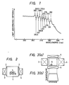
- the concept of the present invention is shown diagrammatically in Fig. 2.
- the system comprises a furnace or a cell or tube 1 with a built-in heater, a pair of windows 2 provided at the ends of the furnace, cell or tube 1, and a light source 3 emitting wavelengths with spectral lines containing the two groups of peaks listed above.
- Light from light source 3 enters the furnace, cell or tube 1 through the left window 2 and emerges therefrom through the window 2 at the other end.
- the heights of the peak intensities of individual spectral lines of the emerging light are measured in a light-receiving unit 4, thereby detecting and quantitatively determining the sulfur in the furnace, cell or tube.
- a hollow cathode lamp is used as the source for emitting spectral lines containing the peaks of the first and second groups and may be equipped with filters through which only the spectral lines corresponding to the specific peaks will pass. Such filters may be provided in the light-receiving unit 4.
- the results of detection may be processed by a computer and displayed on CRT. Being capable of detecting and quantitatively determining sulfur on a semi-real time (substantially real time) basis, this technique will provide a sensitive sulfur monitor capable of on-the-spot detection and quantitative determination of sulfur and control of the sulfur input and pressure.
- Fig. 3(a) is a schematic diagram of the apparatus used in one embodiment of the present invention which comprises a cell 1, a pair of windows 2, a light source 3, a light-receiving unit 4 and heating elements 5.
- This apparatus provides a temperature distribution as shown in the graph of Fig. 3(b).
- Fig. 4 shows the absorption spectrum obtained by heating a gaseous sulfur sample S in the cell 1 at 298°C.
- the spectrum contained a first group of peaks (positive) at wavelengths in nm of 263, 265.5; 268, 270.5, 273, 276, 279 and 282, as well as a second group of peaks (negative) at wavelengths in nm of 264.5, 267, 269.5, 272, 275, 278 and 281.
- the amount of sulfur can be determined by measuring any one of the peaks obtained in the absorption spectrum.
- sulfur can be detected to a precision on the order of 0.01 ppm.
- the evaluation of sulfur content by this approach can be easily and quickly realized with the aid of a computer and other calculating devices, and the measuring system can be controlled while displaying the observed sulfur content on a semi-real time basis.
- the present invention has the following advantages: By making use of the spectrum containing a first group of peaks (positive) and a second group of peaks (negative) that result from the absorption of gaseous sulfur, the invention realized on-the-spot and highly sensitive detection and quantitative determination of gaseous sulfur.
- the high-sensitivity sulfur monitor of the present invention enables on-the-spot detection and quantitative determination of sulfur, and if the monitor is combined with a computer or other calculating devices, semi-real time detection and quantitative determination of sulfur can be performed on the basis of the absorbance for peaks in the spectrum, with the result that output signals from the calculator can be used as data for on-site control of the sulfur input and pressure.
Landscapes
- Physics & Mathematics (AREA)
- Spectroscopy & Molecular Physics (AREA)
- Health & Medical Sciences (AREA)
- Life Sciences & Earth Sciences (AREA)
- Chemical & Material Sciences (AREA)
- Analytical Chemistry (AREA)
- Biochemistry (AREA)
- General Health & Medical Sciences (AREA)
- General Physics & Mathematics (AREA)
- Immunology (AREA)
- Pathology (AREA)
- Investigating Or Analysing Materials By Optical Means (AREA)
Claims (6)
- Ein Verfahren zum Nachweisen und quantitativen Bestimmen von gasförmigem Schwefel, mit den Verfahrensschritten:
Aufheizen einer gasförmigen, Schwefel enthaltenden Probe in einer Probenzelle auf bis etwa 300°C, aber nicht höher;
Hindurchschicken von Nachweisstrahlung durch das Probengas in der Zelle, wobei die Nachweisstrahlung wenigstens eine Spektrallinie aufweist, die aus den Wellenlängen 263, 264.5, 265.5, 267, 268, 269.5, 270.5, 272, 273, 275, 276, 278, 279, 281 und 282 nm ausgewählt ist, wobei die Wellenlängen 263, 265.5, 268, 270.5, 273, 276, 279 und 282 Maxima in der Absorptionskurve des gasförmigen Schwefels entsprechen und die anderen Wellenlängen Senken in der Kurve entsprechen;
Messen der Intensität I für die wenigstens eine ausgewählte Spektrallinie, die in der durch das Probengas tretenden Nachweisstrahlung enthalten ist; und
Bestimmen des Prozentsatzes der Lichtextinktion für die durch die gasförmige Schwefelprobe tretenden Wellenlängen entsprechend der Gleichung

worin I₀ die Intensität der wenigstens einen ausgewählten Spektrallinie, die in Abwesenheit der Schwefelprobe ermittelt wird, bezeichnet; und
Durchführen der quatitativen Bestimmung des gasförmigen Schwefels durch Bestimmen des Wertes C der Konzentration an gasförmigem Schwefel, die entsprechend der Gleichung

vorliegt, wobei k eine für die Wellenlänge spezifische Proportionalitätskonstante für die Wellenlänge ist, welche vorhergehend für eine bekannte Menge von gasförmigem Schwefel bestimmt worden ist. - Ein Verfahren nach Anspruch 1, wobei die erhaltenen Schwefelabsorptionsspektrallinien automatisch analysiert und verarbeitet werden, um eine sofortige Erfassung und Quantifizierung des in dem Probengas vorliegenden Schwefels zu gewährleisten.
- Eine Vorrichtung zum Durchführen des Verfahrens nach Anspruch 1, mit
einem Gefäß (1) mit einem eingebauten Heizer (5), der zu Aufheizung des Gefässes auf eine Temperatur von bis zu etwa 300°C, aber nicht höher, in der Lage ist, und welches mit einer gasförmigen Schwefel enthaltenden Probe gefüllt ist;
einem Paar von Fenstern (2), die in dem Gefäß in der Richtung, in welcher sich die Nachweisstrahlung ausbreitet, vorgesehen sind;
eine Lichtquelle (3), welche Nachweisstrahlung in ein erstes der Fenster hinein emittiert; wobei die Nachweisstrahlung wenigstens eine aus den Wellenlängen 263, 264.5, 265.5, 267, 268, 269.5, 270.5, 272, 273, 275, 276, 278, 279, 281 und 282 ausgewählte Spektrallinie aufweist; und wobei die Wellenlängen 263, 265.5, 268, 270.5, 273, 276, 279 und 282 Maxima in der Absorptionskurve des gasförmigen Schwefels und die anderen Wellenlängen Senken in der Kurve entsprechen;
einer lichtempfangenden photometrischen Einheit (4), die angeordnet ist, um Licht zu empfangen und einen Nachweis und eine quantitative Bestimmung der Lichtextinktion auf der Basis der Höhe der Maximumintensität der wenigstens einen ausgewählten, durch die Probe hindurch übertragenen Spektrallinie durchzuführen. - Vorrichtung nach Anspruch 3, welche ferner eine Computereinrichtung zum Erfassen und quantitativen Bestimmen von Schwefel auf der Basis der Höhe der Maximumintensität der Nachweisstrahlung aufweist, wobei die Schwefelzufuhr und der Druck im wesentlichen auf Echtzeitbasis gesteuert werden.
- Vorrichtung nach Anspruch 3, wobei die Lichtquelleneinrichtung eine Hohlkathodenlampe als die Lichtquelle umfaßt.
- Vorrichtung nach Anspruch 3, welche ferner Filter in einem Ausbreitungsweg der Nachweisstrahlung, durch welche nur die ausgewählte Spektrallinie oder ausgewählten Spektrallinien treten können, umfaßt.
Applications Claiming Priority (6)
| Application Number | Priority Date | Filing Date | Title |
|---|---|---|---|
| JP94485A JPS61160044A (ja) | 1985-01-09 | 1985-01-09 | Sの検知・定量法およびsモニタ− |
| JP944/85 | 1985-01-09 | ||
| JP94385A JPS61160043A (ja) | 1985-01-09 | 1985-01-09 | Sの検知・定量法およびsモニタ− |
| JP943/85 | 1985-01-09 | ||
| JP94585A JPS61160045A (ja) | 1985-01-09 | 1985-01-09 | Sの検知・定量法およびsモニタ− |
| JP945/85 | 1985-01-09 |
Publications (3)
| Publication Number | Publication Date |
|---|---|
| EP0187675A2 EP0187675A2 (de) | 1986-07-16 |
| EP0187675A3 EP0187675A3 (en) | 1987-03-25 |
| EP0187675B1 true EP0187675B1 (de) | 1991-11-27 |
Family
ID=27274678
Family Applications (1)
| Application Number | Title | Priority Date | Filing Date |
|---|---|---|---|
| EP86100248A Expired - Lifetime EP0187675B1 (de) | 1985-01-09 | 1986-01-09 | Verfahren zum Nachweis und zur quantativen Bestimmung von Schwefel und Schwefelmonitor, der dieses Verfahren anwendet |
Country Status (3)
| Country | Link |
|---|---|
| US (1) | US4733084A (de) |
| EP (1) | EP0187675B1 (de) |
| DE (1) | DE3682592D1 (de) |
Families Citing this family (8)
| Publication number | Priority date | Publication date | Assignee | Title |
|---|---|---|---|---|
| US4865746A (en) * | 1987-01-23 | 1989-09-12 | Exxon Research And Engineering Company | Chromatographic analysis of hydrocarbons |
| US4988446A (en) * | 1988-05-14 | 1991-01-29 | Exxon Research And Engineering Company | Method for spectroscopic analysis of hydrocarbons |
| US5076909A (en) * | 1988-05-14 | 1991-12-31 | Exxon Research And Engineering Company | Method for refining or upgrading hydrocarbons with analysis |
| SE503605C2 (sv) * | 1992-01-09 | 1996-07-15 | Svenska Traeforskningsinst | Analysförfarande med UV-absorptionsmätning |
| ATE378580T1 (de) * | 2004-03-09 | 2007-11-15 | Senscient Ltd | Gasnachweis |
| GB2411953A (en) * | 2004-03-09 | 2005-09-14 | Lee Paul Richman | High sensitivity gas detector |
| US10087523B2 (en) | 2016-05-20 | 2018-10-02 | Lam Research Corporation | Vapor delivery method and apparatus for solid and liquid precursors |
| US20170342562A1 (en) * | 2016-05-31 | 2017-11-30 | Lam Research Corporation | Vapor manifold with integrated vapor concentration sensor |
Family Cites Families (3)
| Publication number | Priority date | Publication date | Assignee | Title |
|---|---|---|---|---|
| US3969626A (en) * | 1975-02-18 | 1976-07-13 | E. I. Du Pont De Nemours And Company | Method and apparatus for detecting total reduced sulfur |
| US4322165A (en) * | 1979-02-23 | 1982-03-30 | The Dow Chemical Company | VUV Plasma atomic emission spectroscopic instrument and method |
| US4563585A (en) * | 1982-09-23 | 1986-01-07 | Moniteg Ltd. | Monitoring gas and vapor concentrations |
-
1986
- 1986-01-07 US US06/816,843 patent/US4733084A/en not_active Expired - Lifetime
- 1986-01-09 EP EP86100248A patent/EP0187675B1/de not_active Expired - Lifetime
- 1986-01-09 DE DE8686100248T patent/DE3682592D1/de not_active Expired - Lifetime
Non-Patent Citations (1)
| Title |
|---|
| Handbook of Modern Analytical Instruments by Khandpur, Tab Books US 1981, section 2, pages 62-119 * |
Also Published As
| Publication number | Publication date |
|---|---|
| DE3682592D1 (de) | 1992-01-09 |
| US4733084A (en) | 1988-03-22 |
| EP0187675A3 (en) | 1987-03-25 |
| EP0187675A2 (de) | 1986-07-16 |
Similar Documents
| Publication | Publication Date | Title |
|---|---|---|
| US4373818A (en) | Method and device for analysis with color identification test paper | |
| US3718429A (en) | No-no2 analyzer | |
| US6780378B2 (en) | Method for measuring concentrations of gases and vapors using controlled flames | |
| EP1666870A3 (de) | Analyseverfahren und Vorrichtung für Flüssigproben unter Verwendung von Nahinfrarotspektroskopie | |
| WO1998041825A1 (en) | Method for standardizing raman spectrometers to obtain stable and transferable calibrations | |
| EP1199554A3 (de) | Verfahren und Vorrichtung zur Analyse von Blut mittels Spektroskopie im nahen Infrarot | |
| US3897155A (en) | Atomic fluorescence spectrometer | |
| EP0187675B1 (de) | Verfahren zum Nachweis und zur quantativen Bestimmung von Schwefel und Schwefelmonitor, der dieses Verfahren anwendet | |
| GB1516658A (en) | Method and apparatus for nox analysis | |
| US3988591A (en) | Photometric method for the quantitative determination of a material or substance in an analysis substance and photoelectric photometer for the performance of the aforesaid method | |
| EP1284417A3 (de) | Analysevorrichtung für mehrere Komponenten | |
| Anderson et al. | Ozone absorption cross section measurements in the Wulf bands | |
| GB2026687A (en) | Measurement of oxygen by differential absorption of uv radiation | |
| Liberti | Modern methods for air pollution monitoring | |
| GB1369146A (en) | Chemical analyzer | |
| Tyurin et al. | Determination of sulfur in geological samples and soils using a high-temperature arc plasmatron | |
| Ford et al. | Monitoring the heterogeneously catalyzed conversion of Quadricyclane to Norbornadiene by raman spectroscopy | |
| GB2113833A (en) | Gas analysis apparatus and method of operation | |
| Chen et al. | Raman spectral quantification of Li2SO4, Na2SO4, K2SO4 and Cs2SO4 at 25 to 250° C and its potential implications for the determination of sulfate contents in natural fluid inclusions | |
| US4731334A (en) | Method and apparatus for detecting and quantitatively determining selenium | |
| US3549262A (en) | Apparatus for quantitative analysis of a particular constituent of a sample | |
| Dakin et al. | Optical fibre chemical sensing using direct spectroscopy | |
| Liu | Fiber-Optic Probes | |
| JPH0415412B2 (de) | ||
| JPH0226180B2 (de) |
Legal Events
| Date | Code | Title | Description |
|---|---|---|---|
| PUAI | Public reference made under article 153(3) epc to a published international application that has entered the european phase |
Free format text: ORIGINAL CODE: 0009012 |
|
| AK | Designated contracting states |
Kind code of ref document: A2 Designated state(s): DE FR GB |
|
| PUAL | Search report despatched |
Free format text: ORIGINAL CODE: 0009013 |
|
| AK | Designated contracting states |
Kind code of ref document: A3 Designated state(s): DE FR GB |
|
| 17P | Request for examination filed |
Effective date: 19870410 |
|
| 17Q | First examination report despatched |
Effective date: 19880921 |
|
| GRAA | (expected) grant |
Free format text: ORIGINAL CODE: 0009210 |
|
| AK | Designated contracting states |
Kind code of ref document: B1 Designated state(s): DE FR GB |
|
| REF | Corresponds to: |
Ref document number: 3682592 Country of ref document: DE Date of ref document: 19920109 |
|
| ET | Fr: translation filed | ||
| PLBE | No opposition filed within time limit |
Free format text: ORIGINAL CODE: 0009261 |
|
| STAA | Information on the status of an ep patent application or granted ep patent |
Free format text: STATUS: NO OPPOSITION FILED WITHIN TIME LIMIT |
|
| 26N | No opposition filed | ||
| PGFP | Annual fee paid to national office [announced via postgrant information from national office to epo] |
Ref country code: FR Payment date: 19960109 Year of fee payment: 11 |
|
| PGFP | Annual fee paid to national office [announced via postgrant information from national office to epo] |
Ref country code: DE Payment date: 19960115 Year of fee payment: 11 |
|
| REG | Reference to a national code |
Ref country code: GB Ref legal event code: 746 Effective date: 19970121 |
|
| PG25 | Lapsed in a contracting state [announced via postgrant information from national office to epo] |
Ref country code: FR Effective date: 19970930 |
|
| PG25 | Lapsed in a contracting state [announced via postgrant information from national office to epo] |
Ref country code: DE Effective date: 19971001 |
|
| REG | Reference to a national code |
Ref country code: FR Ref legal event code: ST |
|
| REG | Reference to a national code |
Ref country code: GB Ref legal event code: IF02 |
|
| PGFP | Annual fee paid to national office [announced via postgrant information from national office to epo] |
Ref country code: GB Payment date: 20020109 Year of fee payment: 17 |
|
| PG25 | Lapsed in a contracting state [announced via postgrant information from national office to epo] |
Ref country code: GB Free format text: LAPSE BECAUSE OF NON-PAYMENT OF DUE FEES Effective date: 20030109 |
|
| GBPC | Gb: european patent ceased through non-payment of renewal fee |
Effective date: 20030109 |