EP0187689B1 - Universal equipment for filling valve bags - Google Patents
Universal equipment for filling valve bags Download PDFInfo
- Publication number
- EP0187689B1 EP0187689B1 EP86200042A EP86200042A EP0187689B1 EP 0187689 B1 EP0187689 B1 EP 0187689B1 EP 86200042 A EP86200042 A EP 86200042A EP 86200042 A EP86200042 A EP 86200042A EP 0187689 B1 EP0187689 B1 EP 0187689B1
- Authority
- EP
- European Patent Office
- Prior art keywords
- filling
- bag
- equipment
- erecting
- turntable
- Prior art date
- Legal status (The legal status is an assumption and is not a legal conclusion. Google has not performed a legal analysis and makes no representation as to the accuracy of the status listed.)
- Expired
Links
- 238000007789 sealing Methods 0.000 claims abstract description 21
- 210000003323 beak Anatomy 0.000 claims description 12
- 238000007599 discharging Methods 0.000 claims 1
- HEMHJVSKTPXQMS-UHFFFAOYSA-M Sodium hydroxide Chemical compound [OH-].[Na+] HEMHJVSKTPXQMS-UHFFFAOYSA-M 0.000 description 6
- 230000005484 gravity Effects 0.000 description 3
- 238000003466 welding Methods 0.000 description 3
- 235000011121 sodium hydroxide Nutrition 0.000 description 2
- 238000005516 engineering process Methods 0.000 description 1
- 239000000383 hazardous chemical Substances 0.000 description 1
- 239000012943 hotmelt Substances 0.000 description 1
- 238000012856 packing Methods 0.000 description 1
- 230000001681 protective effect Effects 0.000 description 1
Images


Classifications
-
- B—PERFORMING OPERATIONS; TRANSPORTING
- B65—CONVEYING; PACKING; STORING; HANDLING THIN OR FILAMENTARY MATERIAL
- B65B—MACHINES, APPARATUS OR DEVICES FOR, OR METHODS OF, PACKAGING ARTICLES OR MATERIALS; UNPACKING
- B65B1/00—Packaging fluent solid material, e.g. powders, granular or loose fibrous material, loose masses of small articles, in individual containers or receptacles, e.g. bags, sacks, boxes, cartons, cans, or jars
- B65B1/04—Methods of, or means for, filling the material into the containers or receptacles
- B65B1/18—Methods of, or means for, filling the material into the containers or receptacles for filling valve-bags
-
- B—PERFORMING OPERATIONS; TRANSPORTING
- B65—CONVEYING; PACKING; STORING; HANDLING THIN OR FILAMENTARY MATERIAL
- B65B—MACHINES, APPARATUS OR DEVICES FOR, OR METHODS OF, PACKAGING ARTICLES OR MATERIALS; UNPACKING
- B65B43/00—Forming, feeding, opening or setting-up containers or receptacles in association with packaging
- B65B43/26—Opening or distending bags; Opening, erecting, or setting-up boxes, cartons, or carton blanks
- B65B43/262—Opening or distending bags; Opening, erecting, or setting-up boxes, cartons, or carton blanks opening of valve bags
Definitions
- the invention relates to equipment for erecting and filling valve bags, consisting of a bag supply device, a device provided with a beak for opening and forming the valve, and an erecting clamp for transferring the empty bag from the beak to a filling tube of a filling device.
- Such equipment is known from FR-A-2 504 494.
- the erection clamp has to be kept stationary during the filling of the bag. It will therefore take a considerable time before a new filling can be started.
- the known equipment cannot be used for dangerous products, because the filling tube is horizontal.
- the aim of the invention is to provide equipment for completely automatically filling and sealing both paper and plastic valve bags in various embodiments, i.e. sealed, as well as glued, block bottom and sewn, and with various filling systems, both induced by gravity (filling tube), with air transport or mechanical transport (e.g. a propellor).
- various filling systems both induced by gravity (filling tube), with air transport or mechanical transport (e.g. a propellor).
- Main characteristics of the invented equipment are that the beak is supported in a beak frame and is displaceable in three mutually perpendicular planes in order to transfer the bag to the erecting clamp which is reciprocable in an erecting clamp vertical plane, and that the filling device is provided with a turntable which can be rotated by a filling tube position-changing device about a centre line being at an angle in the order of 45° to the horizontal in a filling tube perpendicular plane of the equipment, said turntable carrying two or a multiple of two filling tubes, each filling tube extending substantially horizontally in the erected position and substantially vertically in the filling position, and that a sealing device is provided for sealing the valve.
- the turntable is supported by means of rollers in relation to a substantially equally large stationary disc and adjacent to a supply tube a seal is provided in the stationary disc which frictionally engages the turntable.
- the filling opening is open only if a bag is suspended from the filling tube.
- the critical moment only occurs when the bag is released and the moment when the turntable rotates, during which it is of major importance that the filling opening is sealed by the disc.
- the sealing device is provided with a sealing portion having a discharge valve.
- the filling device can also be provided with a bag seat, the bottom of which is at an angle to the horizontal, and if the discharge valve slopes downwardly towards a bag discharge chute, a shunting hill-resembling device or discharge drop door is obtained which causes the filled bags to come out on account of the gravity.
- the filling tube vertical plane is at an angle of about 30° to an erection clamp vertical plane of the erecting device.
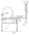
- the equipment shown in the drawing consists of a bag supply device 100 for supplying empty bags from a bag storage magazine, a device 200 for opening and forming the valve of the bag, an erecting device 300 for transferring an empty bag to a filling device 400, a sealing device 500 for sealing the valve of a filled bag, and a bag- ejecting device.
- the bag supply device 100 is generally illustrated by figures 1 and 2, while a few details have been made visible in a larger scale in figures 3 and 4.
- the bag supply device 100 is provided with a supply upper belt 1 and a supply lower belt 6 between which the empty bags in figures 1-3 are supplied from the left to the right and in fig. 4 from the top to the bottom.
- the supply belt 1 is supported in the lower section by a guide table 5 and extends about a return roller 3 and a pressure roller 4 which is urged by a hold-down cylinder 2.
- the hold-down cylinder 2 is supported to a frame 7 by a cylinder pivot 8 which frame also supports a cylinder unit 9 and a linear guide 10 of the device 200 for opening and forming the valve.
- the supply lower belt 6 extends according to fig. 3 about a return roller 11 driven by for example an electro motor 22. This moves the empty bags to a table 21, whereby they are guided by a guiding means 23, and a photo cell 12 situated above the table 21 is activated.
- the table 21 is provided with a stationary suction-pad 20 which can cooperate with a movable upper suction-pad 14 which is connected to a cylinder 13 for reciprocating said pad, operated by the photo cell 12 mentioned before.
- the device 200 for opening and forming the valve essentially comprises a beak 19 mounted on a supporting frame 17.
- the beak 19 is reciprocable along vertical linear guides 18 in the supporting frame 17 by a beak cylinder 15.
- the supporting'frame 17 itself is linearly reciprocable in the direction of the longitudinal centre line of the equipment by a linear/guide drive 16 (fig. 3).
- beak 19 is inserted into the valve of the bag and subsequently moves from the left to the right over the linear guide 10.
- Figures 4 and 5 show that the erection device 300 comprises an erecting clamp 24 which is mounted on a linear guide/drive 25 in order to transfer the bag in an erecting clamp vertical plane A (fig. 2 and 4) to a filling tube 31/32 of the filling device 400, wherein a curve roll 27 connected to the erecting clamp and a curve track 26 attached to the frame 7 cooperate in order to rotate the valve before it is placed onto the filling pipe.
- the erecting clamp 24 is provided with a bag support or underframe 28 which supports the bag during the erection movement and which is provided with a drive 29 for performing its closing movement.
- the upper portion of the erecting clamp is provided with a similar drive 30.
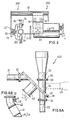
- the filling device 400 shown in fig. 6A has two filling tubes 31 and 32 which are joined to a turntable 38 by connecting flanges 33.
- the turntable can be rotated by a drive 40, and is supported by means of rollers in relation to a stationary disc 37 which is connected to a chute tube flange 35.
- a seal (not shown) is mounted about the outlet of the chute tube, said outlet frictionally engaging the turntable 38.
- the chute tube flange 35 can be connected through a corresponding flange 36 to any chute tube 39. It is also possible to connect the stationary disc 37 to another filling system 45 by a connecting option 34 indicated by a dotted line.
- the filling tubes 31 and 32 extend alternately essentially horizontally in the erection position and essentially vertically in the filling position under the influence of a filling tube position-changing device (not shown).
- a filling tube position-changing device not shown.
- the fact that there are two filling tubes results in a gain of time during filling.
- the passage through the stationary disc 37 and the turntable 38 nearly is open only if a bag is suspended from the filling tube 31 and 32. This is a matter of switch technology which is not further elucidated here.
- the axis of rotation L of the turntable 38 is in a vertical plane B and is at an angle a with respect to the horizontal H.
- the angle a preferably is in the order of 45°.
- the filling tube vertical plane B will coincide with the erection clamp vertical plane A of the erection device 300.
- the filling tube plane B is at an angle in the order of 30° to the erection clamp plane A (fig. 2), some space-saving for the equipment as a whole can be expected. Then it is necessary to embody the filling tubes 31/32 in the manner shown in fig. 6B.
- the filling tube 31/32 is connected to a ring clamp 42 by a rubber bellows and the portion between the ring clamp 42 and the connecting flange 33 is connected to a branch conduct 43 for the bellows and a suction conduct 44.
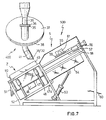
- the closing device 500 shown in fig. 7 consists of a vibrating unit 46 being mounted under a bottom 47 of a bag seat Z which supports the bag in a bag seat frame 52 during filling through the filling tube 31/32.
- the bag seat Z furthermore has a side 49 and a bag bottom support 50 and the structure is reciprocable by means of linear guide/drive 48. During its descent the bag, and thus also the valve thereof, is cleared from the filling tube. In order to be able to automatically empty the bag in case of wrong filling, a cylinder 51 is provided which operates the bottom lid of the bag seat.
- a transport clamp 57 with pertaining drive cylinder 56 and linear guide 58 transfers the filled bag to a sealing member S, where the valve can be sealed in any manner, e.g. ultrasonic welding, heat sealing or hotmelt.
- a plate 47a prevents a filled and sealed bag to slide back into the bag seat Z after said bag has been released by the transport clamp 57.
- the sealing part S consists of a welding horn/anvil 59 with pertaining cutting device, welding unit 61 respectively.
- the sealed bag then rests on a discharge drop door 54 of a bag ejecting device which is tiltable by a discharge cylinder 53 or other linear drive in the direction of a bag discharge chute 60.
- a protective plate 55 When processing health-hazardous substances it is useful to cover the sealing part S by a protective plate 55.
- the sealing device 500 has between the bag seat Z and the sealing part S a shunting hill-resembling device or discharge drop door 54 causing the sealed bags to come out on account of the gravity.
Landscapes
- Engineering & Computer Science (AREA)
- Mechanical Engineering (AREA)
- Basic Packing Technique (AREA)
- Supplying Of Containers To The Packaging Station (AREA)
- Making Paper Articles (AREA)
- Bag Frames (AREA)
- Containers And Packaging Bodies Having A Special Means To Remove Contents (AREA)
Priority Applications (1)
| Application Number | Priority Date | Filing Date | Title |
|---|---|---|---|
| AT86200042T ATE33234T1 (de) | 1985-01-10 | 1986-01-10 | Universelle ausstattung fuer das befuellen von ventilsaecken. |
Applications Claiming Priority (2)
| Application Number | Priority Date | Filing Date | Title |
|---|---|---|---|
| NL8500052A NL8500052A (nl) | 1985-01-10 | 1985-01-10 | Universele installatie voor het vullen van ventielzakken. |
| NL8500052 | 1985-01-10 |
Publications (2)
| Publication Number | Publication Date |
|---|---|
| EP0187689A1 EP0187689A1 (en) | 1986-07-16 |
| EP0187689B1 true EP0187689B1 (en) | 1988-03-30 |
Family
ID=19845347
Family Applications (1)
| Application Number | Title | Priority Date | Filing Date |
|---|---|---|---|
| EP86200042A Expired EP0187689B1 (en) | 1985-01-10 | 1986-01-10 | Universal equipment for filling valve bags |
Country Status (8)
| Country | Link |
|---|---|
| EP (1) | EP0187689B1 (2) |
| JP (1) | JPS61164901A (2) |
| AT (1) | ATE33234T1 (2) |
| CA (1) | CA1260443A (2) |
| DE (1) | DE3660110D1 (2) |
| DK (1) | DK158082C (2) |
| NL (1) | NL8500052A (2) |
| NO (1) | NO161548C (2) |
Families Citing this family (3)
| Publication number | Priority date | Publication date | Assignee | Title |
|---|---|---|---|---|
| JPS63248603A (ja) * | 1987-03-26 | 1988-10-14 | 四国化工機株式会社 | 液体充填装置 |
| EP1232850B1 (de) * | 2001-02-15 | 2008-05-07 | GREIF-VELOX Maschinenfabrik GmbH | Verfahren und Vorrichtung zum Ausbilden und/oder Verschliessen einer Verpackungseinheit |
| AT7676U1 (de) * | 2003-06-11 | 2005-07-25 | Wolfgang Ing Lindner | Mobile sackfüllanlage und verfahren zum betrieb |
Family Cites Families (5)
| Publication number | Priority date | Publication date | Assignee | Title |
|---|---|---|---|---|
| DE2056678A1 (de) * | 1970-11-18 | 1972-05-25 | Haver & Boecker, 4740 Oelde | Fülleinrichtung mit senkrechtem Fallrohr |
| DE2332845A1 (de) * | 1973-06-28 | 1975-01-23 | Mahlkuch Greif Werk Ernst | Ventilsackfuellmaschine mit einem vertikalen fuellstutzen |
| JPS5721510U (2) * | 1980-07-08 | 1982-02-04 | ||
| FR2504494B1 (fr) * | 1981-04-24 | 1985-10-18 | Bates Ventilsaekke | Appareil pour positionner des sacs a valve sur un organe de remplissage |
| DK153679C (da) * | 1981-11-30 | 1988-12-27 | Smidth & Co As F L | Fremgangsmaade for fyldning af pulverformet materiale i ventilsaekke og maskine til udoevelse af fremgangsmaaden |
-
1985
- 1985-01-10 NL NL8500052A patent/NL8500052A/nl not_active Application Discontinuation
-
1986
- 1986-01-08 NO NO860044A patent/NO161548C/no unknown
- 1986-01-08 CA CA000499184A patent/CA1260443A/en not_active Expired
- 1986-01-10 DK DK012786A patent/DK158082C/da active
- 1986-01-10 AT AT86200042T patent/ATE33234T1/de not_active IP Right Cessation
- 1986-01-10 JP JP61003388A patent/JPS61164901A/ja active Granted
- 1986-01-10 EP EP86200042A patent/EP0187689B1/en not_active Expired
- 1986-01-10 DE DE8686200042T patent/DE3660110D1/de not_active Expired
Also Published As
| Publication number | Publication date |
|---|---|
| EP0187689A1 (en) | 1986-07-16 |
| DK12786D0 (da) | 1986-01-10 |
| DK158082B (da) | 1990-03-26 |
| NL8500052A (nl) | 1986-08-01 |
| DK12786A (da) | 1986-07-11 |
| JPH0536281B2 (2) | 1993-05-28 |
| DK158082C (da) | 1990-09-10 |
| NO860044L (no) | 1986-07-11 |
| ATE33234T1 (de) | 1988-04-15 |
| NO161548C (no) | 1989-08-30 |
| JPS61164901A (ja) | 1986-07-25 |
| CA1260443A (en) | 1989-09-26 |
| NO161548B (no) | 1989-05-22 |
| DE3660110D1 (en) | 1988-05-05 |
Similar Documents
| Publication | Publication Date | Title |
|---|---|---|
| CN102180277B (zh) | 一种敞口袋的自动上袋灌装封口设备 | |
| US4142453A (en) | Flexible container inserting apparatus | |
| EP0107474A2 (en) | Method and apparatus for producing bag-shaped packages | |
| IE47313B1 (en) | Bagging machine for packaging powdered materials | |
| US3715858A (en) | Valve bag placer | |
| US3543466A (en) | Method and apparatus for opening,filling and closing of bags | |
| CN114987852B (zh) | 分料机构、灌装设备以及灌装方法 | |
| US3616951A (en) | Carton unloading and stack transferring apparatus | |
| EP0187689B1 (en) | Universal equipment for filling valve bags | |
| CN114803005B (zh) | 一种条形工件自动包装设备 | |
| US3840966A (en) | Apparatus for inserting pressfit cups into can bodies | |
| CN113104330B (zh) | 颗粒制品的调剂系统 | |
| GB1291285A (en) | Improvements in bag placers | |
| US4250691A (en) | Feeding apparatus | |
| US3605383A (en) | Bag dispensing and opening apparatus | |
| US3002326A (en) | A carton forming and handling apparatus | |
| EP2644519B1 (en) | A fitment indexer for a pouch filler | |
| JP2948481B2 (ja) | 封緘装置 | |
| US4671044A (en) | Automatic profile web filler | |
| US3727372A (en) | Bag packaging system | |
| CN115027725B (zh) | 一种自动装盒生产线及装盒工艺 | |
| JP3757044B2 (ja) | 流動食品の充填装置 | |
| JPH03124514A (ja) | 自動袋詰め装置 | |
| US2467766A (en) | Machine for filling receptacles with measured quantities of material | |
| CN210047689U (zh) | 装料设备 |
Legal Events
| Date | Code | Title | Description |
|---|---|---|---|
| PUAI | Public reference made under article 153(3) epc to a published international application that has entered the european phase |
Free format text: ORIGINAL CODE: 0009012 |
|
| AK | Designated contracting states |
Kind code of ref document: A1 Designated state(s): AT BE CH DE FR GB IT LI LU NL SE |
|
| 17P | Request for examination filed |
Effective date: 19860829 |
|
| 17Q | First examination report despatched |
Effective date: 19870402 |
|
| ITF | It: translation for a ep patent filed | ||
| GRAA | (expected) grant |
Free format text: ORIGINAL CODE: 0009210 |
|
| AK | Designated contracting states |
Kind code of ref document: B1 Designated state(s): AT BE CH DE FR GB IT LI LU NL SE |
|
| REF | Corresponds to: |
Ref document number: 33234 Country of ref document: AT Date of ref document: 19880415 Kind code of ref document: T |
|
| REF | Corresponds to: |
Ref document number: 3660110 Country of ref document: DE Date of ref document: 19880505 |
|
| ET | Fr: translation filed | ||
| PLBE | No opposition filed within time limit |
Free format text: ORIGINAL CODE: 0009261 |
|
| STAA | Information on the status of an ep patent application or granted ep patent |
Free format text: STATUS: NO OPPOSITION FILED WITHIN TIME LIMIT |
|
| 26N | No opposition filed | ||
| ITTA | It: last paid annual fee | ||
| PGFP | Annual fee paid to national office [announced via postgrant information from national office to epo] |
Ref country code: LU Payment date: 19931216 Year of fee payment: 9 |
|
| PGFP | Annual fee paid to national office [announced via postgrant information from national office to epo] |
Ref country code: GB Payment date: 19940106 Year of fee payment: 9 |
|
| PGFP | Annual fee paid to national office [announced via postgrant information from national office to epo] |
Ref country code: SE Payment date: 19940111 Year of fee payment: 9 |
|
| PGFP | Annual fee paid to national office [announced via postgrant information from national office to epo] |
Ref country code: AT Payment date: 19940117 Year of fee payment: 9 |
|
| EPTA | Lu: last paid annual fee | ||
| PGFP | Annual fee paid to national office [announced via postgrant information from national office to epo] |
Ref country code: FR Payment date: 19940124 Year of fee payment: 9 |
|
| PGFP | Annual fee paid to national office [announced via postgrant information from national office to epo] |
Ref country code: CH Payment date: 19940126 Year of fee payment: 9 |
|
| PGFP | Annual fee paid to national office [announced via postgrant information from national office to epo] |
Ref country code: BE Payment date: 19940127 Year of fee payment: 9 |
|
| PGFP | Annual fee paid to national office [announced via postgrant information from national office to epo] |
Ref country code: DE Payment date: 19940128 Year of fee payment: 9 |
|
| PGFP | Annual fee paid to national office [announced via postgrant information from national office to epo] |
Ref country code: NL Payment date: 19940131 Year of fee payment: 9 |
|
| PG25 | Lapsed in a contracting state [announced via postgrant information from national office to epo] |
Ref country code: LU Free format text: LAPSE BECAUSE OF NON-PAYMENT OF DUE FEES Effective date: 19950110 Ref country code: GB Effective date: 19950110 Ref country code: AT Effective date: 19950110 |
|
| PG25 | Lapsed in a contracting state [announced via postgrant information from national office to epo] |
Ref country code: SE Effective date: 19950111 |
|
| EAL | Se: european patent in force in sweden |
Ref document number: 86200042.9 |
|
| PG25 | Lapsed in a contracting state [announced via postgrant information from national office to epo] |
Ref country code: LI Effective date: 19950131 Ref country code: CH Effective date: 19950131 Ref country code: BE Effective date: 19950131 |
|
| BERE | Be: lapsed |
Owner name: BATES CEPRO B.V. Effective date: 19950131 |
|
| PG25 | Lapsed in a contracting state [announced via postgrant information from national office to epo] |
Ref country code: NL Effective date: 19950801 |
|
| GBPC | Gb: european patent ceased through non-payment of renewal fee |
Effective date: 19950110 |
|
| PG25 | Lapsed in a contracting state [announced via postgrant information from national office to epo] |
Ref country code: FR Effective date: 19950929 |
|
| REG | Reference to a national code |
Ref country code: CH Ref legal event code: PL |
|
| NLV4 | Nl: lapsed or anulled due to non-payment of the annual fee |
Effective date: 19950801 |
|
| PG25 | Lapsed in a contracting state [announced via postgrant information from national office to epo] |
Ref country code: DE Effective date: 19951003 |
|
| EUG | Se: european patent has lapsed |
Ref document number: 86200042.9 |
|
| REG | Reference to a national code |
Ref country code: FR Ref legal event code: ST |
|
| PG25 | Lapsed in a contracting state [announced via postgrant information from national office to epo] |
Ref country code: IT Free format text: LAPSE BECAUSE OF NON-PAYMENT OF DUE FEES Effective date: 20050110 |