EP0187887B1 - Connecteur avec mécanisme de verrouillage - Google Patents
Connecteur avec mécanisme de verrouillage Download PDFInfo
- Publication number
- EP0187887B1 EP0187887B1 EP85100509A EP85100509A EP0187887B1 EP 0187887 B1 EP0187887 B1 EP 0187887B1 EP 85100509 A EP85100509 A EP 85100509A EP 85100509 A EP85100509 A EP 85100509A EP 0187887 B1 EP0187887 B1 EP 0187887B1
- Authority
- EP
- European Patent Office
- Prior art keywords
- plug
- socket
- locking spring
- plug body
- coupling sleeve
- Prior art date
- Legal status (The legal status is an assumption and is not a legal conclusion. Google has not performed a legal analysis and makes no representation as to the accuracy of the status listed.)
- Expired
Links
- 230000008878 coupling Effects 0.000 claims abstract description 38
- 238000010168 coupling process Methods 0.000 claims abstract description 38
- 238000005859 coupling reaction Methods 0.000 claims abstract description 38
- 230000037431 insertion Effects 0.000 claims abstract description 35
- 238000003780 insertion Methods 0.000 claims abstract description 35
- 239000011810 insulating material Substances 0.000 claims description 4
- 230000002093 peripheral effect Effects 0.000 description 14
- 239000002184 metal Substances 0.000 description 7
- 238000010276 construction Methods 0.000 description 2
- 230000004323 axial length Effects 0.000 description 1
- 230000001419 dependent effect Effects 0.000 description 1
- 230000000694 effects Effects 0.000 description 1
- WABPQHHGFIMREM-UHFFFAOYSA-N lead(0) Chemical compound [Pb] WABPQHHGFIMREM-UHFFFAOYSA-N 0.000 description 1
- 230000000717 retained effect Effects 0.000 description 1
- 238000000926 separation method Methods 0.000 description 1
Images
Classifications
-
- H—ELECTRICITY
- H01—ELECTRIC ELEMENTS
- H01R—ELECTRICALLY-CONDUCTIVE CONNECTIONS; STRUCTURAL ASSOCIATIONS OF A PLURALITY OF MUTUALLY-INSULATED ELECTRICAL CONNECTING ELEMENTS; COUPLING DEVICES; CURRENT COLLECTORS
- H01R13/00—Details of coupling devices of the kinds covered by groups H01R12/70 or H01R24/00 - H01R33/00
- H01R13/62—Means for facilitating engagement or disengagement of coupling parts or for holding them in engagement
- H01R13/627—Snap or like fastening
Definitions
- the present invention relates to a connector for electrically connecting the contacts of a plug and the contacts of a socket by coupling the plug and the socket with each other, and more particularly to a connector having a lock mechanism for locking the plug and the socket together when the plug is inserted in the socket.
- a connector plug according to the prior art portion of claim 1 is disclosed in the document FR-A-2 447 105.
- the locking spring means and the support bar means are together movable with respect to the plug body means and are further movable with respect to each other.
- This prior art when the connector plug has been plugged into the socket, it is necessaryyto manually push the support bar means towards the socket in order to achieve the locking state of the connection.
- This prior art substantially relies upon particular shapes of both movable pieces, the locking spring means and the support bar means.
- This known connector plug does not provide an automatic locking.
- this prior art suffers from the drawback mentioned before since during the connection of plug and socket care must be taken where to hold the plug in order not to interfere with the normal operation of the locking spring means and the support bar means.
- the document FR-A-1455850 relates to a hose connector assembly, wherein, when two counterparts are being connected to each other, the free end of a locking spring provided on one part pushes back one end of a cylinder provided on the other part until a protrusion of the locking spring falls in a recess provided in the body of the other part.
- the cylinder is then pushed forward by a coil spring to confine the locking spring within the cylinder, thereby achieving an automatic locking.
- the cylinder is pulled backward to allow the locking spring to be displaced radially outward to disengage its protrusion from the said recess.
- the locking spring is provided on one and the cylinder on the other of the two counterparts of the assembly.
- the cylinder extends over a substantial length of the respective counterpart but it must not be held while both counterparts are plugged together. Thus, there is again the drawback that care must be taken where to hold the individual parts when they are plugged together.
- the socket to be used with said connector plug is claimed in an independent claim.
- a locking spring means and a support bar means extending axially of the connector plug are disposed in superposed relation, and the support bar means is axially movable and normally urged forwardly under the resiliency of a coil spring.
- the support bar means is caught by a front surface of the socket and the locking spring means is first inserted into an insertion slot defined in the front surface of the socket.
- the support bar means is inserted into the insertion slot under the bias of the coil spring, whereupon the protrusions are retained in the recesses to lock plug and socket together.
- the connector plug can be pulled out of the socket by pulling back a coupling sleeve against the biasing force to withdraw the support bar means out of the insertion slot.
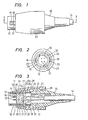
- a plug in a connector according to an embodiment of the present invention is shown in Figs. 1 through 3.
- a plug body 11 is in the form of a cylinder of an insulating material, and a tubular insert 12 is formed integrally with the plug body 11 and extends coaxially therewith toward a position in front of the plug body 11 (see Fig. 4).
- Plug contacts 13 projects forwardly from the plug body 11 in the tubular insert 12.
- the plug contacts 13 comprises pin contacts force-fitted in and extending through small holes (not shown) defined axially through the plug body 11.
- the contacts 13 have rear ends to which are connected lead wires 14a from a cord 14.
- the plug body 11 is fitted at its rear end in a front end of a cap 15, with the cord 14 lead out of a rear end of the cap 15.
- a positioning ridge 16 is integrally formed on an inner peripheral surface of the tubular insert 12 and extends axially thereof.
- locking springs 17 extending axially forwardly are mounted on the plug body 11 and have on free ends thereof protrusions 18 projecting radially outwardly of an axis of the plug body 11.
- the locking springs 17 are resiliently displaceable in radial directions.
- U-shaped slots 19 are formed in the insert 12 to axially extend into the plug body 11 to define the locking springs 17.
- the locking springs 17 have rear ends integrally fixed to the plug body 11 and free front ends from which the protrusions 18 integrally project.
- the locking springs 17 are disposed in diametrically opposite relation to each other.
- a pair of support bars 21 is held against surfaces of the locking springs 17 opposite from the protrusions 18 and is axially movable.
- the support bars 21 are normally urged by a coil spring 22 to move axially in a forward direction, and can be moved back by a coupling sleeve 23 against the resiliency of the coil spring 22.
- the coupling sleeve 23 is axially movably disposed around the plug body 11 and the cap 15.
- the support bars 21 have rear ends integrally connected by a ring member 24 on which there is integrally formed a pair of engagement members 25 extending radially outwardly.
- the cap 15 has axial guide slots 26 defined in a front portion thereof in radial alignment with the engagement members 25.
- the engagement members 25 are guided in the axial guide slots 26 for axial movement therealong, with the engagement members 25 projecting radially outwardly from the guide slots 26.
- the plug body 11 has axial holes 27 positioned radially inwardly of the locking springs 17 and having substantially the same widths as those of the U-shaped slots 19, the axial holes 27 communicating with the slots 19 and the interior of the tubular insert 12.
- the support bars 21 are inserted in the holes 27 and held substantially in contact with inner surfaces of the locking springs 17.
- the support bars 21 have inner surfaces lying flush with or slightly recessed from the inner peripheral surface of the insert 12.
- the coupling sleeve 23 has a ring-shaped recess 28 defined in an inner peripheral surface thereof in which ends of the engagement members 25 are inserted so as to be axially movable.
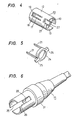
- the coupling sleeve 23 also has locking teeth 29 projecting radially inwardly from the inner peripheral surface of the coupling sleeve 23 at a rear end thereof. Between the locking teeth 29 and the ring-shaped recess 28, there is positioned a ring-shaped stopper 31 (Fig. 6) integrally formed on an outer peripheral surface of the cap 15.
- a portion of the coupling sleeve 23 which is rearward of the ring-shaped recess 28 has a greater inside diameter to define a ring-shaped clearance 32 for allowing the coupling sleeve 23 to be axially moved between the locking teeth 29 and the ring-shaped recess 28.
- the coil spring 22 is interposed between a ring-shaped step 20 formed in an inner peripheral surface of the cap 15 and the engagement members 25 in coaxial relation to the cap 15.
- the coil spring 22 urges the support bars 21 in a forward direction, and also urges the engagement members 25 to engage a front wall surface 28a of the ring-shaped recess 28 to thereby bias the coupling sleeve 23 forwardly. Under this condition, the locking teeth 29 are in engagement with the stopper 31.
- the protrusions 18 of the locking springs 17 are positioned forwardly of the coupling sleeve 23 and project radially outwardly beyond the outer peripheral surface of the insert 12.
- the locking springs 17 project slightly forwardly of the support bars 21.
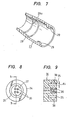
- a socket for use with the plug shown in Figs. 1 through 7 is illustrated by way of example in Figs. 8 and 9.
- a socket body 34 is in the form of a cylinder made of an insulating material and has a ring-shaped insertion slot 35 defined in a front surface thereof.
- Contacts 36 are mounted in the socket body 34 radially inwardly of the slot 35.
- the socket contacts 36 are capable of coupling engagement with the plug contacts 13.
- the socket contacts 36 are in the form of receptacle contacts in which the pin contacts 13 can be inserted.
- the socket contacts 36 are force-fitted in holes defined in the socket body 34.
- the socket body 34 includes an axial positioning groove 37 defined in an inner peripheral surface of the insertion slot 35 for receiving the positioning ridge 16 in the plug (Figs. 2 and 3).
- the socket body 34 also includes locking recesses 38 defined in an outer peripheral surface of the insertion slot 35 for receiving the protrusions 18 of the locking springs 17.
- the sum d, of the thicknesses of the protrusion 18 and the locking spring 17 and the thickness of the support bar 21 is greater than the width d 2 (Fig. 9) of the insertion slot 35.
- the width d 2 of the insertion slot 35 is greater than the sum d 3 of the thickness of the locking spring 17 behind the protrusion 18 and the thickness of the support bar 21.
- the axial length of the ring-shaped clearance 32 is selected such that, with the protrusions 18 engaging in the recesses 38, the support bars 21 can move into and out of the insertion slot 35 or be axially displaced.
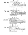
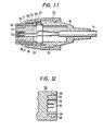
- Each of the protrusions 18 has a front taper 18a (Fig. 10A) sloping down from the top of the protrusion towards the tip end of the locking spring 17 to submerge under the level of the outer peripheral surface of the tubular insert 12 so that when the tubular insert 12 is inserted into the insertion slot 35, an outer edge of the slot 35 abuts the front taper 18a to displace the free end portion of the locking spring 17 radially inwardly.
- the protrusion 18 may also have a rear taper 18b at the rear end thereof, which effects to press the locking spring 17 radially inwardly as the locking spring 17 is pulled out of the insertion slot 35 (Fig. 10D).
- a rear taper 18b at the rear end of the protrusion 18
- the tubular insert 12 of the plug is inserted into the insertion slot 35 in the socket.
- a front portion of the insert 12 extending forward beyond the free end of the locking spring 17 is inserted into the insertion slot 35, relative positioning between the insertion slot 35 and the free end of the locking spring 17 is automatically accomplished so that the outer edge of the insertion slot 35 may abut the front taper 18a of the protrusion 18. Accordingly, the ends of the protrusions 18 are guided into the insertion slot 35 as shown in Fig. 10A. Since the thickness d, of the protrusion 18 and the support bar 21 is greater than the slot width d 2 , as described above, the support bar 21 engages the front surface of the socket body 34 as shown in Fig.
- each support bar 21 it is preferable for each support bar 21 to have a tapered surface 21a on the distal end thereof.
- the coupling sleeve 23 is pulled back against the biasing force of the coil spring 22.
- the support bars 21 are then pulled back through the engagement members 25 until the support bars 21 are brought out of the insertion slot 35 as shown in Fig. 10D. Therefore, the ends of the locking springs 17 can be moved in a direction opposite from the protrusions 18.
- the locking springs 17 are resiliently bent as the protrusions 18 are moved out of the recesses 38, whereupon the plug is unlocked from the socket.
- the plug when the plug is to be inserted into the socket while holding the coupling sleeve 23, the force imposed on the coupling sleeve 23 is applied through the locking teeth 29 to the cap 15.
- the plug can be inserted into the socket.
- the plug can also be inserted into the socket while holding wherever desired on the cap 15.
- the plug can easily be assembled by attaching the contacts 13 to the plug body 11, inserting the support bars 21 through the holes 27 from behind the plug body 11, connecting the cord 14 to the contacts 13, fitting the plug body 11 into the cap 15 with the coil spring 22 housed therein, and then mounting the coupling sleeve 23 onto the plug body 11 and the cap 15 from the front ends thereof.
- the plug can be constructed of relatively simple parts with ease.
- the locking springs 17 are shown as integral with the plug body 11, the locking springs 17 may be integrally formed with the cap 15.
- the locking springs 17 may be positioned radially inwardly of the support bars 21, with the protrusions 18 disposed radially inwardly, and the recesses 38 defined in the inner peripheral surface of the insertion slot35.
- the plug contacts 13 in the plug body 11 may comprise receptacle contacts, and the socket contacts 36 in the socket body 34 may comprise pin contacts.
- the locking spring 17 and the support bar 21 may be combined in one pair or three or more pairs.
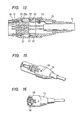
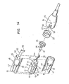
- Figs. 13 through 16 illustrate a plug in a connector according to another embodiment of the present invention. Like or corresponding parts in Figs. 13 through 16 are designated by like or corresponding reference characters in Figs. 1 through 9.
- the plug body 11 is fixed to the cap 15 by auxiliary members. More specifically, the plug body 11 includes an extension 11 a projecting rearwardly of fhe proximal ends of the locking springs 17, and such a rearward extension 11a a has ° an outside diameter smaller than that of the plug body 11, thus defining a ring-shaped step 41.
- a ring member 24 is disposed over the rearward extension 11a, and a coil spring 22 is also disposed over the rearward extension 11a.
- the locking springs 17 project radially outwardly of the outer peripheral surface of the plug body 11, and have integral positioning projections 42, 43 projecting away from each other on the proximal ends of the locking springs 17.
- An edge of the tubular insert 12 comprises projections 44 projecting radially outwardly from the outer peripheral surface of the tubular insert 12.
- Semicylindrical metal members 45,46 serves as auxiliary members for fixing the plug body 11 to the cap 15, and are mounted on the plug body 11 in surrounding relation to the outer peripheral surface thereof.
- Each of the semicylindrical metal members 45,46 has an opening 47 radially aligned with the locking spring 17, recesses 48, 49 communicating with the opening 47 and aligned with the positioning projections 42, 43, and a recess 51 aligned with the projection 44.
- the projections 42, 43,44 are fitted respectively in the recesses 48,49, 51 to position the metal members 45, 46 on the plug body 11.
- the metal members 45, 46 extend rearwardly of the plug body 11, and one of the metal members 45 includes an arm 52 extending rearwardly.
- the rearwardly extending arm 52 is inserted into the cap 15 along an inner surface thereof.
- the arm 52 has a threaded hole 53.
- a screw 55 extends through a small hole 54 in the cap 15 threaded into the threaded hole 53, thus fastening the metal member 45 to the cap 15.
- the cap 15 has two pairs of recesses 56 defined in diametrically opposite front portions thereof. Between the recesses 56 of each pair is formed a tongue in which there is defined a rectangular hole, the tongue with the rectangular hole serving as a holder 57. Thus, there are two such holders 57 on the cap 15 in diametrically opposite relation to each other. As shown in Fig. 16, each of the holders 57 is a double-walled construction having an arcuate groove 58 therein. The rear ends of the metal members 45, 46 are fitted into the arcuate grooves 58, respectively. The coil spring 22 is pushed forwardly by a front end surface of the cap 15.
- the arm 52 has an end serving as a cross- sectionally U-shaped lead-wire holder 59 which holds a plurality of lead wires 14a connected to plug contacts, so that no strong forces will be applied to joints between the lead wires 14a and the contacts when the cord 14 is strongly pulled.
- the coupling sleeve 23 has on an inner surface thereof projections 61 in the shape of a right-angled triangle. When the front end of the cap 15 is inserted into the coupling sleeve 23, the holders 57 are first elastically deformed radially inwardly and then the projections 61 are snapped into the rectangular holes in the holders 57. Therefore, the coupling sleeve 23 is axially movably mounted on the cap 15.
Landscapes
- Details Of Connecting Devices For Male And Female Coupling (AREA)
- Connector Housings Or Holding Contact Members (AREA)
- Measuring Pulse, Heart Rate, Blood Pressure Or Blood Flow (AREA)
Claims (13)
Priority Applications (3)
| Application Number | Priority Date | Filing Date | Title |
|---|---|---|---|
| AT85100509T ATE39596T1 (de) | 1985-01-18 | 1985-01-18 | Steckverbinder mit verriegelungsmechanismus. |
| EP85100509A EP0187887B1 (fr) | 1985-01-18 | 1985-01-18 | Connecteur avec mécanisme de verrouillage |
| DE8585100509T DE3567132D1 (en) | 1985-01-18 | 1985-01-18 | Connector with lock mechanism |
Applications Claiming Priority (1)
| Application Number | Priority Date | Filing Date | Title |
|---|---|---|---|
| EP85100509A EP0187887B1 (fr) | 1985-01-18 | 1985-01-18 | Connecteur avec mécanisme de verrouillage |
Publications (2)
| Publication Number | Publication Date |
|---|---|
| EP0187887A1 EP0187887A1 (fr) | 1986-07-23 |
| EP0187887B1 true EP0187887B1 (fr) | 1988-12-28 |
Family
ID=8193241
Family Applications (1)
| Application Number | Title | Priority Date | Filing Date |
|---|---|---|---|
| EP85100509A Expired EP0187887B1 (fr) | 1985-01-18 | 1985-01-18 | Connecteur avec mécanisme de verrouillage |
Country Status (3)
| Country | Link |
|---|---|
| EP (1) | EP0187887B1 (fr) |
| AT (1) | ATE39596T1 (fr) |
| DE (1) | DE3567132D1 (fr) |
Families Citing this family (8)
| Publication number | Priority date | Publication date | Assignee | Title |
|---|---|---|---|---|
| US4915642A (en) * | 1989-01-19 | 1990-04-10 | Pan-International Industrial Corporation | Trouble-free connector with lock mechanism |
| DE4010836A1 (de) * | 1990-04-04 | 1991-10-10 | Wabco Westinghouse Fahrzeug | Mehrpolige elektrische steckvorrichtung |
| JP2595406Y2 (ja) * | 1992-03-25 | 1999-05-31 | ホシデン株式会社 | プラグ型多極コネクタ |
| FR2697685B1 (fr) * | 1992-11-04 | 1994-12-23 | Jupiter Const Elect | Dispositif de connexion déverrouillable. |
| DE102004039580A1 (de) * | 2004-08-12 | 2006-02-23 | Murr-Elektronik Gmbh | Steckverbinder |
| DK2133958T3 (da) * | 2008-06-09 | 2011-06-06 | Interlemo Holding Sa | Hunstik til selvlåsende forbindelsessystem |
| US11824304B2 (en) | 2022-01-05 | 2023-11-21 | System One Innovations Inc. | Electrical connector |
| CN115473179B (zh) * | 2022-09-23 | 2023-11-21 | 国网冀北电力有限公司廊坊供电公司 | 一种便于拼接的电缆保护套 |
Family Cites Families (7)
| Publication number | Priority date | Publication date | Assignee | Title |
|---|---|---|---|---|
| FR1355766A (fr) * | 1963-02-08 | 1964-03-20 | Jaeger Ets Ed | Connecteur électrique à éléments verrouillés |
| GB1048230A (en) * | 1964-07-09 | 1966-11-16 | Thorn Electrical Ind Ltd | Improvements in and relating to electrical connectors |
| FR1455850A (fr) * | 1965-04-02 | 1966-05-20 | Moulages Ind Plasto | Raccord automatique pour canalisations souples |
| FR1525556A (fr) * | 1966-06-03 | 1968-05-17 | Int Standard Electric Corp | Perfectionnements aux connecteurs électriques |
| SE342495B (fr) * | 1969-12-23 | 1972-02-07 | Larsson Brdr Ind Ab | |
| DE2165037C3 (de) * | 1971-12-28 | 1975-04-30 | Siemens Ag, 1000 Berlin Und 8000 Muenchen | Verriegelung für eine mehrpolige elektrische Steckverbindung |
| FR2447105A2 (fr) * | 1979-01-18 | 1980-08-14 | Souriau & Cie | Perfectionnements aux dispositifs de connexion |
-
1985
- 1985-01-18 EP EP85100509A patent/EP0187887B1/fr not_active Expired
- 1985-01-18 DE DE8585100509T patent/DE3567132D1/de not_active Expired
- 1985-01-18 AT AT85100509T patent/ATE39596T1/de active
Also Published As
| Publication number | Publication date |
|---|---|
| EP0187887A1 (fr) | 1986-07-23 |
| DE3567132D1 (en) | 1989-02-02 |
| ATE39596T1 (de) | 1989-01-15 |
Similar Documents
| Publication | Publication Date | Title |
|---|---|---|
| US4548455A (en) | Connector with lock mechanism | |
| USRE32864E (en) | Connector with lock mechanism | |
| EP0360124B1 (fr) | Fiche de connexion avec un mécanisme de verrouillage | |
| US5195904A (en) | Coaxial electrical connector | |
| US5785546A (en) | Connector locking structure | |
| US5330369A (en) | Connector | |
| US5823813A (en) | Connector position assurance device | |
| US6234826B1 (en) | Connector position assurance device | |
| EP0622869B1 (fr) | Dispositif de connecteur | |
| KR20040058046A (ko) | 커넥터와 대응 커넥터 및 그 조합체 | |
| EP0341419A2 (fr) | Connecteur avec mécanisme de verrouillage | |
| US6609833B1 (en) | Latching system for connector assemblies | |
| CA2416484A1 (fr) | Connecteur verrouillable | |
| EP0477856B1 (fr) | Douille de connexion et connecteur comprenant une douille de connexion et une fiche correspondante | |
| US5702264A (en) | Connector for electric car | |
| US5187862A (en) | Disengaging tool for terminal and wire connector | |
| EP0716478B1 (fr) | Structure et procédé de connexion électrique | |
| JP2001141961A (ja) | 光コネクタ組立体 | |
| US4812007A (en) | Optical fiber connector | |
| WO1992008259A1 (fr) | Dispositif de raccordement d'une fiche a une prise dans un connecteur coaxial | |
| EP0187887A1 (fr) | Connecteur avec mécanisme de verrouillage | |
| JP2000338370A (ja) | 光コネクタ | |
| JPH10247555A (ja) | ラッチ付コネクタ | |
| CN219226695U (zh) | 电气连接器 | |
| JPH08227755A (ja) | コネクタの接続構造 |
Legal Events
| Date | Code | Title | Description |
|---|---|---|---|
| PUAI | Public reference made under article 153(3) epc to a published international application that has entered the european phase |
Free format text: ORIGINAL CODE: 0009012 |
|
| 17P | Request for examination filed |
Effective date: 19850118 |
|
| AK | Designated contracting states |
Kind code of ref document: A1 Designated state(s): AT BE CH DE FR GB IT LI LU NL SE |
|
| RIN1 | Information on inventor provided before grant (corrected) |
Inventor name: EZURE, TADAYOSHI |
|
| 17Q | First examination report despatched |
Effective date: 19870730 |
|
| ITF | It: translation for a ep patent filed | ||
| GRAA | (expected) grant |
Free format text: ORIGINAL CODE: 0009210 |
|
| AK | Designated contracting states |
Kind code of ref document: B1 Designated state(s): AT BE CH DE FR GB IT LI LU NL SE |
|
| REF | Corresponds to: |
Ref document number: 39596 Country of ref document: AT Date of ref document: 19890115 Kind code of ref document: T |
|
| REF | Corresponds to: |
Ref document number: 3567132 Country of ref document: DE Date of ref document: 19890202 |
|
| ET | Fr: translation filed | ||
| PLBE | No opposition filed within time limit |
Free format text: ORIGINAL CODE: 0009261 |
|
| STAA | Information on the status of an ep patent application or granted ep patent |
Free format text: STATUS: NO OPPOSITION FILED WITHIN TIME LIMIT |
|
| 26N | No opposition filed | ||
| ITTA | It: last paid annual fee | ||
| ITPR | It: changes in ownership of a european patent |
Owner name: TRASFORMAZIONE SOCIETARIA;HOSIDEN CORPORATION |
|
| REG | Reference to a national code |
Ref country code: CH Ref legal event code: PFA Free format text: HOSIDEN CORPORATION |
|
| REG | Reference to a national code |
Ref country code: FR Ref legal event code: CD |
|
| EPTA | Lu: last paid annual fee | ||
| NLT1 | Nl: modifications of names registered in virtue of documents presented to the patent office pursuant to art. 16 a, paragraph 1 |
Owner name: HOSIDEN CORPORATION TE YAO, JAPAN. |
|
| EAL | Se: european patent in force in sweden |
Ref document number: 85100509.0 |
|
| PGFP | Annual fee paid to national office [announced via postgrant information from national office to epo] |
Ref country code: BE Payment date: 19951110 Year of fee payment: 12 |
|
| PGFP | Annual fee paid to national office [announced via postgrant information from national office to epo] |
Ref country code: AT Payment date: 19951123 Year of fee payment: 12 |
|
| PGFP | Annual fee paid to national office [announced via postgrant information from national office to epo] |
Ref country code: LU Payment date: 19951201 Year of fee payment: 12 |
|
| PGFP | Annual fee paid to national office [announced via postgrant information from national office to epo] |
Ref country code: SE Payment date: 19951204 Year of fee payment: 12 |
|
| PGFP | Annual fee paid to national office [announced via postgrant information from national office to epo] |
Ref country code: CH Payment date: 19951219 Year of fee payment: 12 |
|
| PGFP | Annual fee paid to national office [announced via postgrant information from national office to epo] |
Ref country code: NL Payment date: 19960131 Year of fee payment: 12 |
|
| PG25 | Lapsed in a contracting state [announced via postgrant information from national office to epo] |
Ref country code: LU Free format text: LAPSE BECAUSE OF NON-PAYMENT OF DUE FEES Effective date: 19970118 Ref country code: AT Effective date: 19970118 |
|
| PG25 | Lapsed in a contracting state [announced via postgrant information from national office to epo] |
Ref country code: SE Effective date: 19970119 |
|
| PG25 | Lapsed in a contracting state [announced via postgrant information from national office to epo] |
Ref country code: LI Effective date: 19970131 Ref country code: CH Effective date: 19970131 Ref country code: BE Effective date: 19970131 |
|
| BERE | Be: lapsed |
Owner name: HOSIDEN ELECTRONICS CO. LTD Effective date: 19970131 |
|
| PG25 | Lapsed in a contracting state [announced via postgrant information from national office to epo] |
Ref country code: NL Effective date: 19970801 |
|
| REG | Reference to a national code |
Ref country code: CH Ref legal event code: PL |
|
| NLV4 | Nl: lapsed or anulled due to non-payment of the annual fee |
Effective date: 19970801 |
|
| EUG | Se: european patent has lapsed |
Ref document number: 85100509.0 |
|
| REG | Reference to a national code |
Ref country code: GB Ref legal event code: IF02 |
|
| PGFP | Annual fee paid to national office [announced via postgrant information from national office to epo] |
Ref country code: FR Payment date: 20031222 Year of fee payment: 20 |
|
| PGFP | Annual fee paid to national office [announced via postgrant information from national office to epo] |
Ref country code: GB Payment date: 20040114 Year of fee payment: 20 |
|
| PGFP | Annual fee paid to national office [announced via postgrant information from national office to epo] |
Ref country code: DE Payment date: 20040129 Year of fee payment: 20 |
|
| PG25 | Lapsed in a contracting state [announced via postgrant information from national office to epo] |
Ref country code: GB Free format text: LAPSE BECAUSE OF EXPIRATION OF PROTECTION Effective date: 20050117 |
|
| REG | Reference to a national code |
Ref country code: GB Ref legal event code: PE20 |