EP0187908A2 - Dispositif pour déplacer des objets ou des personnes - Google Patents
Dispositif pour déplacer des objets ou des personnes Download PDFInfo
- Publication number
- EP0187908A2 EP0187908A2 EP85113885A EP85113885A EP0187908A2 EP 0187908 A2 EP0187908 A2 EP 0187908A2 EP 85113885 A EP85113885 A EP 85113885A EP 85113885 A EP85113885 A EP 85113885A EP 0187908 A2 EP0187908 A2 EP 0187908A2
- Authority
- EP
- European Patent Office
- Prior art keywords
- stage
- belt
- drive
- support plate
- support
- Prior art date
- Legal status (The legal status is an assumption and is not a legal conclusion. Google has not performed a legal analysis and makes no representation as to the accuracy of the status listed.)
- Granted
Links
Images


Classifications
-
- A—HUMAN NECESSITIES
- A61—MEDICAL OR VETERINARY SCIENCE; HYGIENE
- A61G—TRANSPORT, PERSONAL CONVEYANCES, OR ACCOMMODATION SPECIALLY ADAPTED FOR PATIENTS OR DISABLED PERSONS; OPERATING TABLES OR CHAIRS; CHAIRS FOR DENTISTRY; FUNERAL DEVICES
- A61G7/00—Beds specially adapted for nursing; Devices for lifting patients or disabled persons
- A61G7/10—Devices for lifting patients or disabled persons, e.g. special adaptations of hoists thereto
- A61G7/1013—Lifting of patients by
- A61G7/1019—Vertical extending columns or mechanisms
-
- A—HUMAN NECESSITIES
- A61—MEDICAL OR VETERINARY SCIENCE; HYGIENE
- A61G—TRANSPORT, PERSONAL CONVEYANCES, OR ACCOMMODATION SPECIALLY ADAPTED FOR PATIENTS OR DISABLED PERSONS; OPERATING TABLES OR CHAIRS; CHAIRS FOR DENTISTRY; FUNERAL DEVICES
- A61G7/00—Beds specially adapted for nursing; Devices for lifting patients or disabled persons
- A61G7/10—Devices for lifting patients or disabled persons, e.g. special adaptations of hoists thereto
- A61G7/1025—Lateral movement of patients, e.g. horizontal transfer
- A61G7/1032—Endless belts
-
- A—HUMAN NECESSITIES
- A61—MEDICAL OR VETERINARY SCIENCE; HYGIENE
- A61G—TRANSPORT, PERSONAL CONVEYANCES, OR ACCOMMODATION SPECIALLY ADAPTED FOR PATIENTS OR DISABLED PERSONS; OPERATING TABLES OR CHAIRS; CHAIRS FOR DENTISTRY; FUNERAL DEVICES
- A61G7/00—Beds specially adapted for nursing; Devices for lifting patients or disabled persons
- A61G7/10—Devices for lifting patients or disabled persons, e.g. special adaptations of hoists thereto
- A61G7/1025—Lateral movement of patients, e.g. horizontal transfer
- A61G7/1034—Rollers, rails or other means
-
- A—HUMAN NECESSITIES
- A61—MEDICAL OR VETERINARY SCIENCE; HYGIENE
- A61G—TRANSPORT, PERSONAL CONVEYANCES, OR ACCOMMODATION SPECIALLY ADAPTED FOR PATIENTS OR DISABLED PERSONS; OPERATING TABLES OR CHAIRS; CHAIRS FOR DENTISTRY; FUNERAL DEVICES
- A61G7/00—Beds specially adapted for nursing; Devices for lifting patients or disabled persons
- A61G7/10—Devices for lifting patients or disabled persons, e.g. special adaptations of hoists thereto
- A61G7/1049—Attachment, suspending or supporting means for patients
- A61G7/1057—Supported platforms, frames or sheets for patient in lying position
-
- B—PERFORMING OPERATIONS; TRANSPORTING
- B65—CONVEYING; PACKING; STORING; HANDLING THIN OR FILAMENTARY MATERIAL
- B65G—TRANSPORT OR STORAGE DEVICES, e.g. CONVEYORS FOR LOADING OR TIPPING, SHOP CONVEYOR SYSTEMS OR PNEUMATIC TUBE CONVEYORS
- B65G15/00—Conveyors having endless load-conveying surfaces, i.e. belts and like continuous members, to which tractive effort is transmitted by means other than endless driving elements of similar configuration
- B65G15/60—Arrangements for supporting or guiding belts, e.g. by fluid jets
- B65G15/62—Guides for sliding belts
-
- B—PERFORMING OPERATIONS; TRANSPORTING
- B65—CONVEYING; PACKING; STORING; HANDLING THIN OR FILAMENTARY MATERIAL
- B65G—TRANSPORT OR STORAGE DEVICES, e.g. CONVEYORS FOR LOADING OR TIPPING, SHOP CONVEYOR SYSTEMS OR PNEUMATIC TUBE CONVEYORS
- B65G21/00—Supporting or protective framework or housings for endless load-carriers or traction elements of belt or chain conveyors
- B65G21/10—Supporting or protective framework or housings for endless load-carriers or traction elements of belt or chain conveyors movable, or having interchangeable or relatively movable parts; Devices for moving framework or parts thereof
- B65G21/12—Supporting or protective framework or housings for endless load-carriers or traction elements of belt or chain conveyors movable, or having interchangeable or relatively movable parts; Devices for moving framework or parts thereof to allow adjustment of position of load-carrier or traction element as a whole
-
- A—HUMAN NECESSITIES
- A61—MEDICAL OR VETERINARY SCIENCE; HYGIENE
- A61G—TRANSPORT, PERSONAL CONVEYANCES, OR ACCOMMODATION SPECIALLY ADAPTED FOR PATIENTS OR DISABLED PERSONS; OPERATING TABLES OR CHAIRS; CHAIRS FOR DENTISTRY; FUNERAL DEVICES
- A61G2200/00—Information related to the kind of patient or his position
- A61G2200/30—Specific positions of the patient
- A61G2200/32—Specific positions of the patient lying
Definitions
- the invention relates to a device for moving objects or people, comprising a support arrangement, a horizontally displaceably mounted on this stage with a rectangular support plate around which an endless upper conveyor belt movable parallel to the direction of displacement of the stage is guided, and with a belt guide for a parallel lower belt directed towards the conveyor belt, one of the belts being drivable by means of a belt drive, and a displacement drive for the stage.
- Such a device is known for example from DE-OS 26 26 638.
- the band guide for the lower band is formed by a further plate which is connected to the support plate.
- the conveyor belt is moved in such a way that the lower belt is driven as an endless belt by the belt drive and takes the conveyor belt with it by friction. It has been shown in practice that, in particular when using smooth materials for the belts, the frictional connection between the lower belt and the upper conveyor belt is not sufficient to pull even heavy objects or heavy people onto the support plate with the conveyor belt. In this case, the lower belt slipped without the upper conveyor belt moving. From the above-mentioned DE-OS it is already known, additional Lich to drive the conveyor belt to the lower belt. However, this requires an increased drive effort, since a drive connection must be created on the sides of the stage to the upper run of the conveyor belt from the belt drive located below the stage.
- a device for moving patients, in which the conveyor belt is driven directly, is also known from DE-AS 26 06 022.
- the stage has only one edge or an edge over which the patient is pulled up onto the support plate and pulled down again from the support plate.
- the drive device can be arranged in the region of the other edge of the stage.
- this solution is not possible in an embodiment of the type mentioned at the outset, in which, for example, a patient is pulled up over the edge of the stage onto the support plate and pushed back over the other edge of the stage from the support plate.
- Another disadvantage of the known embodiments is that the overall thickness of the stage or of the two panels with the belts is relatively large, since the strength of the individual panels cannot fall below a certain value for reasons of stability. Otherwise, the plates would bend heavily under the weight of the objects or people to be picked up, making it difficult or impossible to adjust the stage and the belts. On the other hand, of course, one strives to make the stage as thin as possible, since it takes place when a person is in between this and its support must be pushed.
- the invention is based on the object of designing a device of the type mentioned at the outset so that, with the simplest possible construction, it enables reliable drive of the conveyor belt and, at the same time, convenient accommodation of the objects or people to be moved.
- the conveyor belt can be driven by the belt drive arranged below the stage.
- the arrangement according to the invention allows an extremely simple direct drive of the conveyor belt. Complicated power transmission mechanisms, such as were proposed in DE-OS 26 26 638 for the direct drive of the conveyor belt, can be omitted.
- the drive for the upper conveyor belt is not only easier on the e _ findungs- contemporary embodiment but Above all, it also requires considerably less space.
- the support plate preferably has a depression in the area of the free stage edges on its underside, into which the bar for guiding the lower band can be immersed. Even if the thickness of the support plate is small in the area of this recess, the stability of the support plate as a whole is not impaired by this. On the other hand, the overall thickness of the stage to be pushed under the person to be recorded is practically reduced to the thickness of the support plate by this embodiment. This makes picking up an object or a person considerably easier and more gentle for a patient, for example.
- a further advantageous embodiment according to the invention is that the strips are connected at their ends to swivel arms directed perpendicular to the longitudinal direction of the strips, which are each articulated on the support plate about an axis directed parallel to the longitudinal direction of the strips. Due to this arrangement, the strips can be pivoted away from the support plate or the conveyor belt together with the lower belt, so that all belt surfaces, in particular the lower belt, can be cleaned and disinfected by wiping, whereas in conventional embodiments with a finite lower belt, this in the Usually only partially can be cleaned directly.
- This aspect is particularly for the use of the device according to the invention in locks for transferring patients between a non-sterile area and a sterile area of paramount importance.
- the support arrangement comprises at least one vertical support column and a height-adjustable support arrangement on which the stage is horizontally displaceable
- the movable parts of the displacement drive for the stage and the height adjustment drive attached to the carrier assembly for the carrier assembly together with the belt drive.
- pressure-responsive contact elements are arranged in the front upper region of the strips and / or in the lower region of the deflection edges of the support plate, which are connected to the belt drive in this way that they switch it off when a pressure exceeds a certain threshold value is applied.
- These contact elements are preferably designed as contact strips which extend over the entire receiving width of the stage.
- a heating device is installed in the support plate.
- the heating device is preferably arranged as surface heating directly on the underside of the upper boundary plate of the support plate, the space between the heating device and the lower boundary plate of the support plate being foamed with plastic.
- a voltage source which is electrically isolated from the line network is preferably provided for the heating device in order to generate a voltage of less than 220 volts, preferably 60 volts or 24 volts.
- the heating device normally does not require thermostatic control, the electrical parameters being such that the heating power is approximately 0.5 to 1.5 watts per dm 2 of heated area.
- FIG. 1 shows a schematically illustrated hatch 10 in a partition between two rooms 12 and 14.
- the hatches can be, for example, a sterile and a non-sterile room in a hospital, the hatch 10 being intended for patients.
- the hatch can be closed by a vertically adjustable window 16.
- the device to be described below is used to move patients between rooms 12 and 14 after opening window 16.
- the displacement device comprises a support arrangement, generally designated 18, which is vertically adjustable on vertical supports 20 on both sides of the pass-through opening, as is shown in FIGS. 2 to 4 will be described in more detail below.
- the carrier arrangement 18 comprises a carrier frame with vertical frame side parts 22 which are connected to one another by a horizontal carrier 24 (FIGS. 1 and 2).
- a stage, generally designated 26, is adjustably mounted on the support frame in the direction of the double arrow P (FIG. 1).
- the stage 26 comprises two side cheeks 28 and between them a support plate 30.
- a C-shaped rail 32 is formed, in which 22 freely rotatably mounted rollers 34 engage on the frame side parts, as well as this can be seen in Fig. 2.
- An endless conveyor belt 36 is guided over the support plate 30, which covers the entire support plate 30 between the side cheeks 28 with its upper strand 38 and is guided with its lower strand 40 via deflection rollers 42 around a drive roller 44, so that it covers most of its circumference wraps around.
- the drive roller 44 is rotatably mounted on the frame side parts 22 with an axis 46 parallel to the window plane 16 and can be driven in both directions of rotation via a drive chain 48 by a motor 50 in the carrier arrangement 18.
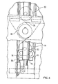
- the support plate 30 is enclosed by a metal frame 54, the longitudinal profiles of which run perpendicular to the direction of displacement P of the stage 22 each have on their underside a recess 56 running parallel to them, into which a deflection strip 58 for a lower band 60 is immersed.
- the deflection strip 58 is connected at its longitudinal ends to a swivel arm 62, which is shown in broken lines in FIG. 9.
- the swivel arms 62 are pivoted approximately in the middle of the support plate 30 about an axis 64 or 66 parallel to the axis 46 of the drive roller 44, so that the frame consisting of the swivel arms 62 and the respective deflecting strip 58 is pulled out between those in FIG Lines represented upper position and the lower position represented by dashed lines can be pivoted.
- the lower finite belt 60 is fastened to the carrier frame with its two ends 68 and 70 and is passed through the carrier arrangement 18 below the drive roller 44 by means of deflection rollers 72, 72.
- the lower belt 50 cannot therefore be moved as a whole.
- a relative movement to the deflection strips 58 occurs when the stage 30 is horizontally displaced in the direction of the double arrow P.
- the thickness or thickness of the stage section lying between the side walls 28 is practically the same as the thickness of the support plate 30, while in conventional devices of the generic type, this section has twice the thickness, since two plates are used to guide the two bands.
- the displacement of the stage 26 in the direction of the double arrow P takes place with the aid of a further drive motor 74, which is located behind the motor 50 in the viewing direction in FIG. 1 and is flanged to the frame side part 22 (FIG. 2).
- Its output shaft drives a gear 80 via a gear 76 and a drive chain 78, which gear sits on a shaft 82 which is mounted coaxially to the drive roller 44 and drives a gear 86 which is freely rotatably mounted on the frame side part 22 via a drive chain 84.
- the height adjustment of the support arrangement 18 together with the stage 26 is carried out by means of a height adjustment drive, which will now be explained with reference to FIGS. 2, 3 and 4.
- the height adjustment drive comprises a drive motor 92 flanged to a frame side part 22, which drives via a drive chain 94 a shaft 96 directed parallel to the drive roller 44, which is mounted in bearings 98 fastened to the underside of the carrier 24 and each has a sprocket wheel at its free ends 100 carries.
- a sprocket 102 is freely rotatably mounted on the outside of the frame side part 22. These sprockets 102 and 100 are engaged with a stationary vertical chain 104, as shown in FIG. 4.
- the chain 104 is stretched between tensioning elements 106 and 108, which are fastened to the support column 20. If the sprocket 100 is driven by the drive motor 92, the entire support arrangement including the stage and all drives moves up or down, being guided on support surfaces 112 of the support columns 20 by means of rollers 110 in the manner shown in FIG. 3 .
- the rollers 110 are mounted on a vertical rail 114 connected to the support frame, between which and the associated frame side part 22 the sprockets 100 and 102 are arranged.
- the carrier arrangement 18 is supported in each case by means of a gas spring 116 arranged in the support columns 20. This gas spring 116 also serves to cushion the support arrangement if the height adjustment fails for some reason and the support arrangement 18 should fall down as a result.
- the entire support arrangement forms a closed unit, to which the control cabinet 118, which can still be seen in FIG. 1, belongs.
- the chain drive for the height adjustment of the carrier arrangement and the spring elements 116 are provided on both sides of the pass-through opening, while on one side of the carrier arrangement, as shown in FIG. 2, the motor 74 for moving the stage 26 and on the other side of the hatch the motor 50 for the belt drive are arranged in mirror-image positions.
- the guidance of the stage 26 on the carrier arrangement 18, the chain drive for its displacement and the belt drive are otherwise identical on both sides of the pass-through opening.
- FIG. 6 shows a bed 120 with a schematically represented patient 122, the stage 26 initially being essentially in the room 14.
- the stage 26 with the support plate 30 is pushed under the patient 122, as indicated by dashed lines in FIG. 6.
- the support plate 30 is displaced at the speed v p , the circumferential speed v A of the drive roller is 2vp, the upper run 38 of the conveyor belt 36 remaining stationary, that is to say not moving in the direction of the double arrow P.
- the patient is pulled up onto the support plate 30 by the conveyor belt 36, so that he assumes the position shown by solid lines in FIG. 7.
- the stage 26 is now shifted from the left position shown by solid lines in FIG. 7 into the room 14 into the position shown by dashed lines.
- a relative speed of the upper run 38 of the conveyor belt 36 relative to the space of 2v results, while the relative speed of the upper run 38 relative to the support plate 30 is equal to v p .
- This causes not only the stage 26 to be transported from left to right, but also the patient 122 from the left side of the support plate 30 to its right side, as can be seen in FIG. 7.
- the stage 26 is now shifted to the left with the same speed data as in the step shown in FIG. 6 into the position shown by dashed lines, the patient 122 on a mobile couch 124 is filed.
- Fig. 9 shows that by folding the deflecting strips 58 of the lower belt 60 this can be folded away from the support plate 30 and the upper conveyor belt 36, so that all belt sections of the upper and lower belt 36 and 60 are cleaned and disinfected by wiping can.
- the stage 26 can be moved to the left from the position shown in FIG. 9, the left deflection bar 58 then being folded down and the cleaning and disinfecting process being able to be repeated there.
- the support plate 30 consists of a circumferential metal frame 54, a foam core 126 enclosed by it and cover plates 128 and 130 covering it upwards and downwards.
- a heating foil 132 is glued to the underside of the upper cover plate 128 , which is indicated by dashed lines in FIGS. 1 and 5. It is supplied with energy via a spiral cable 134 (FIGS. 1 and 2) arranged in one of the cheeks 28, the heating voltage being less than 220 volts, preferably 60 volts or 24 volts.
- This heating voltage can be supplied galvanically isolated from the mains via a transformer.
- the heating output should be approx. 0.5 to 1.5 watts per dm 2 . In this way it is possible to heat the surface of the support plate 30 to a temperature which is adapted to the body temperature of a patient to be transferred.
- a thermostatic heating control can be dispensed with.
- FIG. 1 A further feature of the present invention can be seen in FIG.
- contact strips are arranged 136 and 138, and a drive in a manner not shown the drive motor 50 of the B are connected such that they border when exposed to a a certain threshold Pressure cause the belt drive to switch off. This provides security against the drawing-in of bed sheets, patient's clothing and the like between the support plate 30 and the deflection strips 58.
- the invention has been described above with reference to a stationary displacement device. It goes without saying that the configuration of the displacement device according to the invention can also be provided in the case of mobile displacement devices which, for example, serve to take patients out of their bed, move them to another room and place them there again on a support.
Landscapes
- Health & Medical Sciences (AREA)
- General Health & Medical Sciences (AREA)
- Nursing (AREA)
- Life Sciences & Earth Sciences (AREA)
- Animal Behavior & Ethology (AREA)
- Public Health (AREA)
- Veterinary Medicine (AREA)
- Mechanical Engineering (AREA)
- Engineering & Computer Science (AREA)
- Invalid Beds And Related Equipment (AREA)
- Structure Of Belt Conveyors (AREA)
- Reciprocating Conveyors (AREA)
- Framework For Endless Conveyors (AREA)
Applications Claiming Priority (2)
| Application Number | Priority Date | Filing Date | Title |
|---|---|---|---|
| DE3446017 | 1984-12-17 | ||
| DE19843446017 DE3446017A1 (de) | 1984-12-17 | 1984-12-17 | Vorrichtung zum verlagern von gegenstaenden oder personen |
Publications (3)
| Publication Number | Publication Date |
|---|---|
| EP0187908A2 true EP0187908A2 (fr) | 1986-07-23 |
| EP0187908A3 EP0187908A3 (en) | 1987-04-29 |
| EP0187908B1 EP0187908B1 (fr) | 1990-02-28 |
Family
ID=6253008
Family Applications (1)
| Application Number | Title | Priority Date | Filing Date |
|---|---|---|---|
| EP85113885A Expired - Lifetime EP0187908B1 (fr) | 1984-12-17 | 1985-10-31 | Dispositif pour déplacer des objets ou des personnes |
Country Status (4)
| Country | Link |
|---|---|
| US (1) | US4669137A (fr) |
| EP (1) | EP0187908B1 (fr) |
| JP (3) | JPS61145010A (fr) |
| DE (4) | DE3446017A1 (fr) |
Cited By (1)
| Publication number | Priority date | Publication date | Assignee | Title |
|---|---|---|---|---|
| DE8704343U1 (de) * | 1987-03-24 | 1987-06-25 | MTP Medizintechnische Produkte GmbH, 52134 Herzogenrath | Vorrichtung zum Übernehmen von liegend zu transportierenden Patienten aus einem Bett |
Families Citing this family (24)
| Publication number | Priority date | Publication date | Assignee | Title |
|---|---|---|---|---|
| US4794655A (en) * | 1986-04-25 | 1989-01-03 | Agency Of Industrial Science & Technology | Truck type patient-moving device |
| US4761841A (en) * | 1987-05-11 | 1988-08-09 | Larsen Ralph E | Hospital gurney having a patient transfer device |
| DE3738882A1 (de) * | 1987-11-16 | 1989-05-24 | Fuchs & Fuchs Gmbh | Umlagerungsgeraet fuer patienten |
| DE3814972C1 (fr) * | 1988-05-03 | 1989-05-18 | Blanco Gmbh & Co Kg, 7519 Oberderdingen, De | |
| JPH0368343A (ja) * | 1989-08-09 | 1991-03-25 | Toshiba Corp | 医用寝台装置 |
| DE3938622C1 (fr) * | 1989-11-21 | 1991-06-06 | Stierlen-Maquet Ag, 7550 Rastatt, De | |
| DE4041335C1 (fr) * | 1990-12-21 | 1992-01-16 | Stierlen-Maquet Ag, 7550 Rastatt, De | |
| DE10014208A1 (de) | 2000-03-22 | 2001-10-11 | Maquet Ag | Verfahren und Vorrichtung zum Verlagern von Patienten |
| JP4402930B2 (ja) * | 2003-09-29 | 2010-01-20 | 株式会社ダイヘン | 移載装置および移載装置アッセンブリ |
| WO2007044231A2 (fr) * | 2005-10-07 | 2007-04-19 | Conmedisys, Inc. | Dispositif de levage et de transfert de patient |
| US9107788B2 (en) | 2005-10-07 | 2015-08-18 | MediGlider Corp. | Cam mechanism to raise steering wheel of patient transfer device |
| US7603729B2 (en) * | 2005-10-07 | 2009-10-20 | Conmedisys, Inc. | Patient lift and transfer device |
| US8214943B2 (en) | 2005-10-07 | 2012-07-10 | Conmedisys, Inc. | Steering system for patient transfer device |
| US20080034495A1 (en) * | 2006-01-06 | 2008-02-14 | Stidd Raymond E | Patient gurney |
| US9668929B2 (en) | 2010-10-08 | 2017-06-06 | Conmedisys, Inc. | Patient transfer device with differential belt-table speed control |
| US9655800B1 (en) * | 2016-09-16 | 2017-05-23 | Salvus Transportare, LLC | Support apparatus with double roller assembly |
| CN106743179A (zh) * | 2016-12-05 | 2017-05-31 | 重庆奇甫机械有限责任公司 | 一种托盘结构以及套筒加工中心 |
| CN106580602B (zh) * | 2016-12-26 | 2018-12-04 | 燕山大学 | 双向转运护理机器人 |
| US12145805B2 (en) * | 2019-06-04 | 2024-11-19 | Nidec Motor Corporation | Integrated conveyor motor |
| CN112294575B (zh) * | 2020-11-03 | 2022-04-15 | 西南交通大学 | 一种可移动病床装置 |
| US20230117987A1 (en) * | 2021-10-20 | 2023-04-20 | Takai Tofu & Soymilk Equipment Co. | Tofu conveying machine |
| US12440411B2 (en) | 2022-03-30 | 2025-10-14 | Able Innovations Inc. | Transfer device with platform plate having two-sided functionality and treatment system |
| US11628111B1 (en) * | 2022-03-30 | 2023-04-18 | Able Innovations Inc. | Transfer device with platform plate having two-sided functionality |
| US12440396B2 (en) | 2022-03-30 | 2025-10-14 | Able Innovations Inc. | Transfer device with platform plate having two-sided functionality and treatment system |
Family Cites Families (12)
| Publication number | Priority date | Publication date | Assignee | Title |
|---|---|---|---|---|
| BE688786A (fr) * | 1965-10-24 | 1967-04-24 | ||
| US3579672A (en) * | 1970-02-05 | 1971-05-25 | Diamondhead Properties Inc | Method and apparatus for moving objects |
| US3765037A (en) * | 1972-04-05 | 1973-10-16 | Diamondhead Corp | Apparatus for transferring objects |
| US3768629A (en) * | 1972-09-05 | 1973-10-30 | Economation Inc | Unit load conveying apparatus |
| GB1429208A (en) * | 1972-12-04 | 1976-03-24 | Siemens Ag | Hatch for mounting in a wall mechanism for feeding and locating magnetic cores in a device for interweaving memory matrices with a coiled wire |
| US3947902A (en) * | 1975-03-17 | 1976-04-06 | Mobilizer Medical Products, Inc. | Apron and drive mechanism for object transferring apparatus |
| CA1097716A (fr) * | 1975-10-08 | 1981-03-17 | Allen J. Balboni | Matelas chauffant electrique et sous-ensembles connexes |
| JPS5281988A (en) * | 1975-12-27 | 1977-07-08 | Toyoda Chuo Kenkyusho Kk | Apparatus for transfering materials |
| DE2626638A1 (de) * | 1976-06-14 | 1977-12-22 | Stierlen Maquet Ag | Transporteinrichtung zum verlagern von liegenden patienten, insbesondere in krankenhaeusern |
| CA1165813A (fr) * | 1980-05-08 | 1984-04-17 | Michael J. Domeniconi | Pile electrochimique et solution electrochimique connexe |
| JPS59124611A (ja) * | 1982-12-30 | 1984-07-18 | Shimadzu Corp | 物体移送装置 |
| US4534077A (en) * | 1983-10-03 | 1985-08-13 | Simmons Universal Corporation | Hospital bed having safety mechanism |
-
1984
- 1984-12-17 DE DE19843446017 patent/DE3446017A1/de not_active Withdrawn
- 1984-12-17 DE DE3448299A patent/DE3448299C2/de not_active Expired - Lifetime
- 1984-12-17 DE DE19843448420 patent/DE3448420C2/de not_active Expired - Lifetime
-
1985
- 1985-10-31 DE DE8585113885T patent/DE3576115D1/de not_active Expired - Lifetime
- 1985-10-31 EP EP85113885A patent/EP0187908B1/fr not_active Expired - Lifetime
- 1985-12-10 US US06/807,251 patent/US4669137A/en not_active Expired - Lifetime
- 1985-12-17 JP JP60284168A patent/JPS61145010A/ja active Pending
-
1994
- 1994-08-24 JP JP6199697A patent/JPH07250869A/ja active Pending
- 1994-08-24 JP JP6199696A patent/JPH07250868A/ja active Pending
Cited By (1)
| Publication number | Priority date | Publication date | Assignee | Title |
|---|---|---|---|---|
| DE8704343U1 (de) * | 1987-03-24 | 1987-06-25 | MTP Medizintechnische Produkte GmbH, 52134 Herzogenrath | Vorrichtung zum Übernehmen von liegend zu transportierenden Patienten aus einem Bett |
Also Published As
| Publication number | Publication date |
|---|---|
| DE3446017A1 (de) | 1986-06-19 |
| DE3448299C2 (en) | 1990-04-26 |
| JPS61145010A (ja) | 1986-07-02 |
| DE3576115D1 (de) | 1990-04-05 |
| EP0187908B1 (fr) | 1990-02-28 |
| JPH07250868A (ja) | 1995-10-03 |
| US4669137A (en) | 1987-06-02 |
| JPH07250869A (ja) | 1995-10-03 |
| DE3448420C2 (de) | 1992-12-17 |
| EP0187908A3 (en) | 1987-04-29 |
Similar Documents
| Publication | Publication Date | Title |
|---|---|---|
| EP0187908B1 (fr) | Dispositif pour déplacer des objets ou des personnes | |
| DE2317111C3 (de) | Transportvorrichtung zum Verlagern von Gegenständen | |
| DE2906000C2 (de) | Massagevorrichtung für eine medizinische Behandlung | |
| AT391617B (de) | Bett, insbesondere krankenhausbett | |
| DE3303925C2 (de) | Massageeinrichtung | |
| DE2740807A1 (de) | Bandfoerderer | |
| DD248729A5 (de) | Vorrichtung zum kontinuierlichen ausziehen eines teigstreifens | |
| DE3340322C2 (de) | Ausziehbarer Stetigförderer | |
| AT503307B1 (de) | Vorrichtung und verfahren zum ausbreiten von lebensmittelteig | |
| DE3029385A1 (de) | Vorrichtung zur behandlung photographischer filme und papiere | |
| DE2129871A1 (de) | Krankenbahre | |
| DE2140672C3 (de) | Garagentor | |
| DE1052314B (de) | Foerdereinrichtung fuer Tragrahmen, insbesondere fuer Teigwarentrockner, mit mehreren uebereinander angeordneten Stockwerken | |
| DE2704114C2 (de) | Kühl- oder Gefrieranlage | |
| DE7618579U1 (de) | Schiebefenster, insbesondere fuer fahrzeuge | |
| DE1466914B2 (de) | Patientenlagerstatt fuer roentgenuntersuchungsgeraete | |
| DE2638566C3 (de) | Im Freien verwendbarer Förderer mit einer geschlossenen Laufbahn für mehrere Wagen | |
| EP0959219A2 (fr) | Elément de paroi de séparation autopropulsé | |
| DE2714446C3 (de) | Kastenförmige Kabine zum Reinigen und Entseuchen von Bettgestell u.dgl. | |
| DE4424650C1 (de) | Vorrichtung zum schmerzlosen Aufnehmen und/oder Transportieren von Patienten | |
| DE3430515A1 (de) | Vorrichtung zum heben und senken eines bettgestelles | |
| DE2249383B2 (de) | Teigbearbeitungsanlage | |
| DE614938C (de) | Hebetisch fuer Blechwalzwerke | |
| DE3045616A1 (de) | Einrichtung zum aufgeben von stueckguetern auf foerderbaender o.dgl. | |
| DE3619837A1 (de) | Hebegeraet fuer die pflege von bettlaegerigen personen |
Legal Events
| Date | Code | Title | Description |
|---|---|---|---|
| PUAI | Public reference made under article 153(3) epc to a published international application that has entered the european phase |
Free format text: ORIGINAL CODE: 0009012 |
|
| AK | Designated contracting states |
Kind code of ref document: A2 Designated state(s): AT BE CH DE FR GB IT LI LU NL SE |
|
| RBV | Designated contracting states (corrected) |
Designated state(s): DE FR GB IT |
|
| PUAL | Search report despatched |
Free format text: ORIGINAL CODE: 0009013 |
|
| AK | Designated contracting states |
Kind code of ref document: A3 Designated state(s): DE FR GB IT |
|
| 17P | Request for examination filed |
Effective date: 19870515 |
|
| 17Q | First examination report despatched |
Effective date: 19880712 |
|
| GRAA | (expected) grant |
Free format text: ORIGINAL CODE: 0009210 |
|
| AK | Designated contracting states |
Kind code of ref document: B1 Designated state(s): DE FR GB IT |
|
| REF | Corresponds to: |
Ref document number: 3576115 Country of ref document: DE Date of ref document: 19900405 |
|
| ITF | It: translation for a ep patent filed | ||
| ET | Fr: translation filed | ||
| GBT | Gb: translation of ep patent filed (gb section 77(6)(a)/1977) | ||
| PLBE | No opposition filed within time limit |
Free format text: ORIGINAL CODE: 0009261 |
|
| STAA | Information on the status of an ep patent application or granted ep patent |
Free format text: STATUS: NO OPPOSITION FILED WITHIN TIME LIMIT |
|
| 26N | No opposition filed | ||
| ITTA | It: last paid annual fee | ||
| PGFP | Annual fee paid to national office [announced via postgrant information from national office to epo] |
Ref country code: FR Payment date: 19960924 Year of fee payment: 12 |
|
| PGFP | Annual fee paid to national office [announced via postgrant information from national office to epo] |
Ref country code: GB Payment date: 19961022 Year of fee payment: 12 |
|
| REG | Reference to a national code |
Ref country code: FR Ref legal event code: CD |
|
| PG25 | Lapsed in a contracting state [announced via postgrant information from national office to epo] |
Ref country code: GB Free format text: LAPSE BECAUSE OF NON-PAYMENT OF DUE FEES Effective date: 19971031 Ref country code: FR Free format text: THE PATENT HAS BEEN ANNULLED BY A DECISION OF A NATIONAL AUTHORITY Effective date: 19971031 |
|
| GBPC | Gb: european patent ceased through non-payment of renewal fee |
Effective date: 19971031 |
|
| REG | Reference to a national code |
Ref country code: FR Ref legal event code: ST |
|
| PGFP | Annual fee paid to national office [announced via postgrant information from national office to epo] |
Ref country code: DE Payment date: 19981130 Year of fee payment: 14 |
|
| PG25 | Lapsed in a contracting state [announced via postgrant information from national office to epo] |
Ref country code: DE Free format text: LAPSE BECAUSE OF NON-PAYMENT OF DUE FEES Effective date: 20000801 |